EP2363570A2 - Dispositif de moteur tubulaire pour un dispositif d'obscurcissement - Google Patents
Dispositif de moteur tubulaire pour un dispositif d'obscurcissement Download PDFInfo
- Publication number
- EP2363570A2 EP2363570A2 EP10013767A EP10013767A EP2363570A2 EP 2363570 A2 EP2363570 A2 EP 2363570A2 EP 10013767 A EP10013767 A EP 10013767A EP 10013767 A EP10013767 A EP 10013767A EP 2363570 A2 EP2363570 A2 EP 2363570A2
- Authority
- EP
- European Patent Office
- Prior art keywords
- sensor
- tubular motor
- closure element
- triggering
- axis
- Prior art date
- Legal status (The legal status is an assumption and is not a legal conclusion. Google has not performed a legal analysis and makes no representation as to the accuracy of the status listed.)
- Granted
Links
Images



Classifications
-
- E—FIXED CONSTRUCTIONS
- E06—DOORS, WINDOWS, SHUTTERS, OR ROLLER BLINDS IN GENERAL; LADDERS
- E06B—FIXED OR MOVABLE CLOSURES FOR OPENINGS IN BUILDINGS, VEHICLES, FENCES OR LIKE ENCLOSURES IN GENERAL, e.g. DOORS, WINDOWS, BLINDS, GATES
- E06B9/00—Screening or protective devices for wall or similar openings, with or without operating or securing mechanisms; Closures of similar construction
- E06B9/56—Operating, guiding or securing devices or arrangements for roll-type closures; Spring drums; Tape drums; Counterweighting arrangements therefor
- E06B9/68—Operating devices or mechanisms, e.g. with electric drive
- E06B9/72—Operating devices or mechanisms, e.g. with electric drive comprising an electric motor positioned inside the roller
-
- E—FIXED CONSTRUCTIONS
- E06—DOORS, WINDOWS, SHUTTERS, OR ROLLER BLINDS IN GENERAL; LADDERS
- E06B—FIXED OR MOVABLE CLOSURES FOR OPENINGS IN BUILDINGS, VEHICLES, FENCES OR LIKE ENCLOSURES IN GENERAL, e.g. DOORS, WINDOWS, BLINDS, GATES
- E06B9/00—Screening or protective devices for wall or similar openings, with or without operating or securing mechanisms; Closures of similar construction
- E06B9/56—Operating, guiding or securing devices or arrangements for roll-type closures; Spring drums; Tape drums; Counterweighting arrangements therefor
- E06B9/80—Safety measures against dropping or unauthorised opening; Braking or immobilising devices; Devices for limiting unrolling
- E06B9/82—Safety measures against dropping or unauthorised opening; Braking or immobilising devices; Devices for limiting unrolling automatic
- E06B9/88—Safety measures against dropping or unauthorised opening; Braking or immobilising devices; Devices for limiting unrolling automatic for limiting unrolling
-
- G—PHYSICS
- G01—MEASURING; TESTING
- G01D—MEASURING NOT SPECIALLY ADAPTED FOR A SPECIFIC VARIABLE; ARRANGEMENTS FOR MEASURING TWO OR MORE VARIABLES NOT COVERED IN A SINGLE OTHER SUBCLASS; TARIFF METERING APPARATUS; MEASURING OR TESTING NOT OTHERWISE PROVIDED FOR
- G01D5/00—Mechanical means for transferring the output of a sensing member; Means for converting the output of a sensing member to another variable where the form or nature of the sensing member does not constrain the means for converting; Transducers not specially adapted for a specific variable
- G01D5/12—Mechanical means for transferring the output of a sensing member; Means for converting the output of a sensing member to another variable where the form or nature of the sensing member does not constrain the means for converting; Transducers not specially adapted for a specific variable using electric or magnetic means
- G01D5/14—Mechanical means for transferring the output of a sensing member; Means for converting the output of a sensing member to another variable where the form or nature of the sensing member does not constrain the means for converting; Transducers not specially adapted for a specific variable using electric or magnetic means influencing the magnitude of a current or voltage
- G01D5/142—Mechanical means for transferring the output of a sensing member; Means for converting the output of a sensing member to another variable where the form or nature of the sensing member does not constrain the means for converting; Transducers not specially adapted for a specific variable using electric or magnetic means influencing the magnitude of a current or voltage using Hall-effect devices
- G01D5/145—Mechanical means for transferring the output of a sensing member; Means for converting the output of a sensing member to another variable where the form or nature of the sensing member does not constrain the means for converting; Transducers not specially adapted for a specific variable using electric or magnetic means influencing the magnitude of a current or voltage using Hall-effect devices influenced by the relative movement between the Hall device and magnetic fields
-
- E—FIXED CONSTRUCTIONS
- E06—DOORS, WINDOWS, SHUTTERS, OR ROLLER BLINDS IN GENERAL; LADDERS
- E06B—FIXED OR MOVABLE CLOSURES FOR OPENINGS IN BUILDINGS, VEHICLES, FENCES OR LIKE ENCLOSURES IN GENERAL, e.g. DOORS, WINDOWS, BLINDS, GATES
- E06B9/00—Screening or protective devices for wall or similar openings, with or without operating or securing mechanisms; Closures of similar construction
- E06B9/56—Operating, guiding or securing devices or arrangements for roll-type closures; Spring drums; Tape drums; Counterweighting arrangements therefor
- E06B9/68—Operating devices or mechanisms, e.g. with electric drive
- E06B2009/6809—Control
- E06B2009/6818—Control using sensors
- E06B2009/6845—Control using sensors sensing position
-
- E—FIXED CONSTRUCTIONS
- E06—DOORS, WINDOWS, SHUTTERS, OR ROLLER BLINDS IN GENERAL; LADDERS
- E06B—FIXED OR MOVABLE CLOSURES FOR OPENINGS IN BUILDINGS, VEHICLES, FENCES OR LIKE ENCLOSURES IN GENERAL, e.g. DOORS, WINDOWS, BLINDS, GATES
- E06B9/00—Screening or protective devices for wall or similar openings, with or without operating or securing mechanisms; Closures of similar construction
- E06B9/56—Operating, guiding or securing devices or arrangements for roll-type closures; Spring drums; Tape drums; Counterweighting arrangements therefor
- E06B9/68—Operating devices or mechanisms, e.g. with electric drive
- E06B2009/6809—Control
- E06B2009/6872—Control using counters to determine shutter position
Definitions
- the invention relates to a tubular motor arrangement for a darkening device or safety device according to the preamble of claim 1.
- the tubular motor assembly in question can be used for a variety of dimming devices or security devices. All that is essential is that the obscuring device or securing device has an adjustable closure element. Examples of such an adjustable closure element are blinds, blinds, shutters, awnings, roller shutters or roller blinds.
- the known tubular motor arrangement ( DE 20 2007 016 283 U1 ), from which the invention proceeds, serves primarily the motorized adjustment of a shutter.
- the tubular motor assembly is equipped with a drive motor and a transmission downstream of the drive motor.
- the drive motor is associated with a drive control with a Wegmessan extract for determining the current position of the shutter.
- determination of the current position is meant here that a value is determined as a measure of the current position, which can be compared with a stored position setpoint.
- the displacement measuring arrangement of the known tube motor arrangement operates on the one hand according to the principle of an incremental sensor and on the other hand, for "fine measurement", at least in an end position according to the principle of time measurement. Accordingly, the known arrangement is regularly designed so that the sensor device generates substantially digital sensor signals.
- the present invention is based on the problem, the known tubular motor assembly to design and further develop such that the displacement measuring arrangement is further optimized, especially with regard to the collision detection.
- the sensor device can advantageously be designed as a magnetoresistive sensor.
- the basic principle of a magnetoresistive sensor is that the electrical conductivity of an electrical measuring conductor can be influenced by the application of this magnetic field to a magnetic field.
- MR effect magnetoresistive effect
- AMR effect anisotropic magnetoresistive effect
- GMR effect giant magnetoresistive effect
- the sensor is associated with a sensor plane, wherein by means of the sensor, the direction of a magnetic field within the sensor plane is continuously detected. If the sensor plane is thus penetrated by a magnetic field, it can be detected by means of the sensor device which direction the portion of the magnetic field lying in the sensor plane has.
- the sensor device has an adjustable triggering element arrangement with at least one triggering magnet, which always generates a magnetic field-sensor field in the sensor plane.
- the triggering element assembly is optionally coupled via intermediate elements such as a winding shaft or the like with the closure element, so that the adjustment of the closure element determines the direction of the sensor field.
- the continuous course of the generated sensor signals has a very special advantage in terms of collision detection, in particular during the downward movement of a roller shutter. Because there are continuously changing sensor signals during an adjustment, it can conversely be concluded in the absence of a signal change that the closure element is stationary, which possibly goes back to a collision. This detection of the stoppage of the closure element is possible in no time, without having to wait for a signal period or the like. Immediate detection and the associated possibility of being able to react quickly to collisions is an essential aspect of the proposed solution.
- the claims 3 to 6 relate to the arrangement of the sensor on the one hand and the trigger element arrangement on the other.
- An interesting aspect is the fact that with the proposed measures practically a transfer of the movement of the closure element around the tube motor axis has been achieved on a change in direction of the sensor field occurring in the sensor plane (claims 3 and 4).
- the claims 7 and 8 relate to the embodiment of the magnetoresistive sensor with two integrated magnetoresistive sensor elements, wherein it has been proven according to claim 8, the sensor axes of the two sensor elements with respect to the tubular motor transverse axis by the same angular amount, but opposite, hiring.
- the sensor axis of a sensor element in question represents a reference axis lying in particular in the sensor plane for the angular position of the magnetic field flowing through the sensor element. This means that a magnetic field which is at a specific angle to the sensor axis in the sensor plane is at this angle outputs assigned sensor signal.
- the collision detection is the subject of claims 10 to 13.
- the drive motor to couple with the closure element via a freewheel drive technology. It is therefore possible in the scope of the freewheel that the drive motor is running, even if the closure element, for example by a collision, is blocked. This non-adjustment of the closure element can be detected immediately via the change indicator according to claim 11. If the change indicator falls below a lower limit, a collision routine is triggered according to claim 12. If the closure element is not in a predefined, upper near range, the falling below the lower limit causes an immediate shutdown of the drive motor.
- the proposed solution is shown in the drawing with reference to a darkening device with an adjustable closure element 1 configured as a roller shutter.
- the proposed drive arrangement is applicable to many variants of dimming devices or security devices. An exemplary selection has been given in the introductory part of the description.
- the tubular motor assembly is equipped with a tubular housing 2, in which a drive motor 3 and preferably also a drive 4 downstream of the drive motor 3 is or are arranged. Optionally, can also be dispensed with a downstream transmission 4.
- the drive motor 3 is assigned a drive control 5, the drive control 5 having a displacement measuring arrangement for determining the position of the closure element 1.
- Fig. 2 shows the position of the components drive motor 3, 4 gear and drive control 5 schematically.
- Fig. 3 shows the installation position of the drive control 5 in an exploded view. The structural design of the drive arrangement shown will be explained in more detail below.
- the displacement measuring arrangement has a sensor device 6 and preferably a position counter, wherein the sensor device 6 generates periodic sensor signals during an adjustment of the closure element 1, as will be explained below.
- the sensor device 6 has a magnetoresistive sensor 7, which in the Fig. 3 to 5 can be seen schematically.
- the sensor 7 is soldered onto a circuit board 8 as an integrated component (IC).
- the magnetoresistive sensor 7 is associated with a sensor plane 9, wherein by means of the sensor 7, the direction of a magnetic field within the sensor plane 9 can be detected.
- the direction detection relates, as explained above, only the directional component of a sensor 7 penetrating magnetic field, which lies in the sensor plane 9.
- the sensor signal of a magnetoresistive sensor usually has a sinusoidal profile over the angle of the magnetic field within the sensor plane 9.
- the sensor device 6 has an adjustable triggering element arrangement 10 with four triggering magnets 11. In principle, it may be sufficient here to provide only a single triggering magnet 11.
- the trigger element arrangement 10 is designed such that it generates a magnetic field-sensor field-in the sensor plane 9.
- the trigger element assembly 10 is coupled in the mounted state here via a winding shaft 12 with the closure element 1, so that the adjustment of the closure element 1 determines the direction of the sensor field within the sensor plane 9.
- the sensor device 6 on the one hand and the triggering element arrangement 10 on the other hand are now designed and arranged such that each adjustment of the closure element 1 is associated with a change in the sensor signals.
- the advantages associated with the continuous change of the sensor signals during the adjustment of the closure element 1 have been explained in the general part of the description.
- the tubular motor assembly has here and preferably at one end a tubular motor head 13 for connection to a fixed counter bearing and at the other end a driver 14 for the drive technology coupling with the winding shaft 6.
- the tubular motor assembly is inserted in the assembled state in the winding shaft 12 such that the closure element 1 by means of the tubular motor assembly on the winding shaft 12 can be wound and unwound from the winding shaft 12.
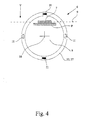
- a particularly advantageous embodiment of the trigger element assembly 10 results from a synopsis of Fig. 3 and 4 ,
- the tubular motor assembly in the region of the tubular motor head 13 has an adapter ring 15 which is rotatable relative to the tubular motor assembly, moreover, here about the tubular motor axis 16.
- the winding shaft 12 is rotatably mounted relative to the tubular motor assembly via the adapter ring 15, wherein the trigger element assembly 10 is associated with the adapter ring 15.
- the trigger element assembly 10 may be part of the adapter ring 15 or coupled to the adapter ring 15.
- the adapter ring 15 is a ring 17 - - associated magnetic ring 17 - which is moved with a rotation of the adapter ring 15 ( Fig. 3 ).
- the magnetic ring 17 here and preferably corresponds to the triggering element arrangement 10.
- the sensor 7 is arranged such that the tubular motor axis 16 is substantially parallel to the sensor plane 9.
- the tubular motor axis 16 extends essentially through the sensor plane 9. In a particularly preferred embodiment shown here, however, it is the case that the tube motor axis 16 is offset parallel to the sensor plane 9.
- the at least one triggering magnet 11 is aligned parallel to the tubular motor axis 16 with respect to its dipole axis 11a. This can be easily achieved by appropriate design, that of the at least one triggering magnet 11 generated, the sensor device 6 penetrating magnetic field relative to the tubular motor axis 16 at least in a position of the closure element 1 is at least substantially radially aligned.
- Fig. 4 refers to the fact that the at least one triggering magnet 11 relative to the tubular motor axis 16 on one of the trigger element assembly 10 associated circumference is, wherein the magnetoresistive sensor 7 is seen in the direction of the tubular motor axis 16 within this scope.
- the trigger element assembly 10 thus surrounds the sensor 7, wherein in principle a relative to the tube motor axis 16 axial offset between the trigger magnet 11 and the sensor 7 is provided ( Fig. 5 ). Without this offset, the above alignment of the sensor array would not be feasible.
- the here and preferably four triggering magnets 11 are axially aligned with each other in terms of a symmetrical relative to the tubular motor axis 16 training the sensor field.
- a single triggering magnet 11 is sufficient to detect the position of the closure element 1.
- continuously changing sensor signals are at least two, here four trigger magnets 11 are provided, which are distributed over the the trigger element assembly 10 associated circumference around the tubular motor axis 16 around, here evenly distributed, are arranged.
- the sensor 7 is preferably integrated magnetoresistive sensor elements 18, 19 each with a lying in particular in the sensor plane 9 Sensor axis 18a, 19a, wherein the sensor axes 18a, 19a are angularly offset by an offset angle a to each other.
- this offset is at 45 °, wherein the one sensor axis 18a forms the main axis of the sensor 7 in total.
- the sensor 7 is preferably an integrated component (IC).
- Fig. 5 are the sensor elements 18, 19 merely indicated. Another position of the two sensor elements 18, 19 relative to each other, in particular a nested arrangement, is conceivable. Also, the offset between the two sensor elements 18, 19 shown with respect to the sensor axis 18a has been chosen only in the sense of a clear representation.
- the phase shift essentially results from the angular offset between the two sensor elements 18, 19.
- the proposed sensor device 6 can be used in different ways for determining the position of the closure element 1.
- the sensor signals during the adjustment of the shutter member 1 periodic counting events for the position counter ready.
- Such count events may be the edges, the extremes, or the like of the above-mentioned mutually phase-shifted sinusoidal sensor signals.
- the occurrence of such counting events causes the position counter to increment or decrement by one counting step. This corresponds to the operation of an incremental sensor.
- a timing device may additionally be provided, with which, triggered by a counting event, the current time interval - time interval - can be measured to just this count event. It is assumed that the adjustment speed of the closure element 1 is substantially constant, so that the time interval together with the count overall provides an accurate measure of the adjustment of the closure element 1.
- this position entry please refer to the German utility model mentioned in the introductory part of the description 20 2007 016 283.9 dated 20 November 2007, which goes back to the Applicant and the content of which is the subject of this application in its entirety.
- the drive motor 3 is drivingly coupled to the closure element 1 via a freewheel, wherein a blocking of the closure element 1, for example, by a collision with an obstacle with a subsequent passage of the freewheel is accompanied by substantially stationary closure element 1.
- a blocking of the closure element 1 for example, by a collision with an obstacle with a subsequent passage of the freewheel is accompanied by substantially stationary closure element 1.
- the freewheel is here and preferably provided between the driver 9 and the driver 9 associated drive axle.
- the detection of a collision therefore results from the fact that the drive motor is running, but the displacement measuring arrangement does not signal any movement of the closure element 1 when passing through the freewheel.
- the displacement measuring arrangement does not signal any movement of the closure element 1 when passing through the freewheel.
- the drive control 5 preferably continuously determines a value for the current change of the sensor signals with respect to time, which is referred to below as the "change indicator".
- a blocking of the closure element 1 for example by icing or just by a collision, causes a falling below a lower limit of the change indicator.
- Such a jerky move is also referred to as "sloshing back".
- the change indicator now allows a very simple detection of collisions.
- the drive controller 5 triggers a collision routine when the lower limit value is undershot by the change indicator and causes an immediate shutdown of the drive motor 3 in the collision routine.
- the blocking of the closure element 1 can be detected largely without delay.
- the drive control 5 does not cause a shutdown of the drive motor 3 during downward travel in the collision routine.
- the shutdown is only made up if the upper limit value is not exceeded by a predetermined time was determined by the change indicator, ie the "back spill".
- This predetermined time preferably corresponds to the nominal leaving the upper near range. This means that after a certain time it is to be expected that the upper near range has actually been left.
- the shutdown of the drive motor 3 in the upper vicinity of the designed as a shutter shutter element 1 is thus reset until it is ensured that the blocking of the closure element 1 does not correspond to the normal operation behavior. This ensures that the collision detection with subsequent shutdown does not lead to an unwanted obstruction of Verstell worriess.
Landscapes
- Engineering & Computer Science (AREA)
- Structural Engineering (AREA)
- Architecture (AREA)
- Civil Engineering (AREA)
- Physics & Mathematics (AREA)
- General Physics & Mathematics (AREA)
- Operating, Guiding And Securing Of Roll- Type Closing Members (AREA)
Applications Claiming Priority (1)
| Application Number | Priority Date | Filing Date | Title |
|---|---|---|---|
| DE202010003095U DE202010003095U1 (de) | 2010-03-02 | 2010-03-02 | Rohrmotoranordnung für eine Verdunkelungsvorrichtung |
Publications (3)
| Publication Number | Publication Date |
|---|---|
| EP2363570A2 true EP2363570A2 (fr) | 2011-09-07 |
| EP2363570A3 EP2363570A3 (fr) | 2014-10-15 |
| EP2363570B1 EP2363570B1 (fr) | 2017-12-06 |
Family
ID=43218035
Family Applications (1)
| Application Number | Title | Priority Date | Filing Date |
|---|---|---|---|
| EP10013767.8A Active EP2363570B1 (fr) | 2010-03-02 | 2010-10-19 | Dispositif de moteur tubulaire pour un dispositif d'obscurcissement |
Country Status (2)
| Country | Link |
|---|---|
| EP (1) | EP2363570B1 (fr) |
| DE (2) | DE202010003095U1 (fr) |
Cited By (1)
| Publication number | Priority date | Publication date | Assignee | Title |
|---|---|---|---|---|
| CN105840080A (zh) * | 2016-05-19 | 2016-08-10 | 广州市瑞翔机电有限公司 | 一种用于窗帘开合系统的带手拉起动的控制器 |
Families Citing this family (4)
| Publication number | Priority date | Publication date | Assignee | Title |
|---|---|---|---|---|
| FR2975426B1 (fr) * | 2011-05-17 | 2018-03-02 | Somfy Sas | Tete d'actionneur electromecanique de manoeuvre d'un element enroulable |
| DE102011117609A1 (de) | 2011-11-04 | 2013-05-08 | Arca Beteiligungen Gmbh | Steuerungsanordnung |
| DE102012003697A1 (de) | 2012-02-28 | 2013-08-29 | Arca Beteiligungen Gmbh | Intelligente Hinderniserkennung |
| DE102016009769A1 (de) | 2016-08-02 | 2018-02-08 | Theben Ag | Schaltungsanordnung |
Citations (1)
| Publication number | Priority date | Publication date | Assignee | Title |
|---|---|---|---|---|
| DE202007016283U1 (de) | 2007-11-13 | 2009-03-26 | Arca Beteiligungen Gmbh | Antriebsanordnung für eine Verdunkelungsvorrichtung |
Family Cites Families (5)
| Publication number | Priority date | Publication date | Assignee | Title |
|---|---|---|---|---|
| DE3608988A1 (de) * | 1986-03-18 | 1987-09-24 | Lothar Huber | Vorrichtung zur handbetaetigung einer elektromotorisch antreibbaren wickelwelle z.b. eines rolladens |
| FR2780090B1 (fr) * | 1998-06-19 | 2000-08-11 | Deprat Jean Sa | Dispositif d'entrainement d'un organe, notamment tambour de volet roulant, et dispositif de protection d'une ouverture, notamment volet roulant, equipe d'un dispositif d'entrainement |
| FR2869349B1 (fr) * | 2004-04-26 | 2008-01-04 | Jouvence Sarl | Procede de commande du mouvement d'un tablier de volet roulant et dispositif pour la mise en oeuvre du procede |
| WO2006008218A1 (fr) * | 2004-07-23 | 2006-01-26 | Jolly Motor International S.P.A. | Detecteur de position angulaire pour le pilotage de dispositif incorporant un moteur a pignons tubulaires pour volets roulants |
| FR2932212B1 (fr) * | 2008-06-09 | 2014-02-21 | Bubendorff | Dispositif de fermeture a tablier ou store repliable ou enroulable et a moteur d'entrainement electrique |
-
2010
- 2010-03-02 DE DE202010003095U patent/DE202010003095U1/de not_active Expired - Lifetime
- 2010-03-19 DE DE102010012182A patent/DE102010012182A1/de not_active Withdrawn
- 2010-10-19 EP EP10013767.8A patent/EP2363570B1/fr active Active
Patent Citations (1)
| Publication number | Priority date | Publication date | Assignee | Title |
|---|---|---|---|---|
| DE202007016283U1 (de) | 2007-11-13 | 2009-03-26 | Arca Beteiligungen Gmbh | Antriebsanordnung für eine Verdunkelungsvorrichtung |
Cited By (1)
| Publication number | Priority date | Publication date | Assignee | Title |
|---|---|---|---|---|
| CN105840080A (zh) * | 2016-05-19 | 2016-08-10 | 广州市瑞翔机电有限公司 | 一种用于窗帘开合系统的带手拉起动的控制器 |
Also Published As
| Publication number | Publication date |
|---|---|
| EP2363570A3 (fr) | 2014-10-15 |
| DE102010012182A1 (de) | 2010-12-30 |
| DE202010003095U1 (de) | 2011-11-16 |
| EP2363570B1 (fr) | 2017-12-06 |
Similar Documents
| Publication | Publication Date | Title |
|---|---|---|
| DE10037211B4 (de) | Lenkradstellungssensor | |
| EP2363570B1 (fr) | Dispositif de moteur tubulaire pour un dispositif d'obscurcissement | |
| EP3563117B1 (fr) | Dispositif de détection | |
| EP0938646B1 (fr) | Systemes pour detecter un mouvement rotatif ou translatoire | |
| DE19712869A1 (de) | Lenkwinkelsensorsystem mit erhöhter Redundanz | |
| EP0988510B1 (fr) | Detecteur de course | |
| EP2063336B2 (fr) | Dispositif d'entraînement pour un dispositif d'obscurcissement | |
| WO2011134823A2 (fr) | Système de détection incrémentiel de positions multiples pour un système de transfert électromagnétique en boucle fermée | |
| EP1036303B1 (fr) | Dispositif de mesure pour determiner sans contact un angle de rotation | |
| DE102016106181A1 (de) | Absperrarmatur | |
| CH697773B1 (de) | Magnetischer Drehwinkelsensor. | |
| DE102011103576A1 (de) | Drehwinkelsensor | |
| EP1471337B1 (fr) | Dispositif de mesure du niveau d'un liquide dans un contenant | |
| DE19543352C2 (de) | Lotsystem zur Füllstandsmessung | |
| EP2343506B1 (fr) | Dispositif de mesure de longueur | |
| DE102011109551A1 (de) | Messsystem zur Positionsbestimmung eines gegenüber einem Referenzkörper verschiebbaren oder verdrehbaren Körpers mit einem magnetischen Encoder | |
| DE102009038087A1 (de) | Kugelgewindetrieb | |
| DE102010010239B4 (de) | Anordnung zur Detektion der Anzahl der Umdrehungen eines relativ zu einem Impulsdrahtsensor oder Wieganddrahtsensor drehbar gelagerten Teils | |
| DE3929937A1 (de) | Mit magnetkraeften arbeitender endlagensensor | |
| DE19535011A1 (de) | Niveaumeßvorrichtung zum Messen des Füllstandes von Behältern | |
| DE102010048173B3 (de) | Verfahren zur Justierung eines Sensorkopfes einer Nadelüberwachungseinrichtung und Nadelüberwachungseinrichtung | |
| DE102009024551A1 (de) | Zaunpfosten mit verschwenkbarem Ausleger | |
| EP3470363B1 (fr) | Procédé et système de commande d'enroulement ou de déroulement d'une section de câble sur ou d'un tambour rotatif | |
| DE19947370C2 (de) | Wegsensor | |
| DE2556284B2 (de) | Grenzwertsignaleinrichtung |
Legal Events
| Date | Code | Title | Description |
|---|---|---|---|
| PUAI | Public reference made under article 153(3) epc to a published international application that has entered the european phase |
Free format text: ORIGINAL CODE: 0009012 |
|
| AK | Designated contracting states |
Kind code of ref document: A2 Designated state(s): AL AT BE BG CH CY CZ DE DK EE ES FI FR GB GR HR HU IE IS IT LI LT LU LV MC MK MT NL NO PL PT RO RS SE SI SK SM TR |
|
| AX | Request for extension of the european patent |
Extension state: BA ME |
|
| PUAL | Search report despatched |
Free format text: ORIGINAL CODE: 0009013 |
|
| AK | Designated contracting states |
Kind code of ref document: A3 Designated state(s): AL AT BE BG CH CY CZ DE DK EE ES FI FR GB GR HR HU IE IS IT LI LT LU LV MC MK MT NL NO PL PT RO RS SE SI SK SM TR |
|
| AX | Request for extension of the european patent |
Extension state: BA ME |
|
| RIC1 | Information provided on ipc code assigned before grant |
Ipc: E06B 9/72 20060101AFI20140911BHEP Ipc: E06B 9/88 20060101ALI20140911BHEP |
|
| 17P | Request for examination filed |
Effective date: 20150225 |
|
| RBV | Designated contracting states (corrected) |
Designated state(s): AL AT BE BG CH CY CZ DE DK EE ES FI FR GB GR HR HU IE IS IT LI LT LU LV MC MK MT NL NO PL PT RO RS SE SI SK SM TR |
|
| GRAP | Despatch of communication of intention to grant a patent |
Free format text: ORIGINAL CODE: EPIDOSNIGR1 |
|
| STAA | Information on the status of an ep patent application or granted ep patent |
Free format text: STATUS: GRANT OF PATENT IS INTENDED |
|
| INTG | Intention to grant announced |
Effective date: 20170808 |
|
| GRAS | Grant fee paid |
Free format text: ORIGINAL CODE: EPIDOSNIGR3 |
|
| GRAA | (expected) grant |
Free format text: ORIGINAL CODE: 0009210 |
|
| STAA | Information on the status of an ep patent application or granted ep patent |
Free format text: STATUS: THE PATENT HAS BEEN GRANTED |
|
| AK | Designated contracting states |
Kind code of ref document: B1 Designated state(s): AL AT BE BG CH CY CZ DE DK EE ES FI FR GB GR HR HU IE IS IT LI LT LU LV MC MK MT NL NO PL PT RO RS SE SI SK SM TR |
|
| REG | Reference to a national code |
Ref country code: GB Ref legal event code: FG4D Free format text: NOT ENGLISH |
|
| REG | Reference to a national code |
Ref country code: AT Ref legal event code: REF Ref document number: 952549 Country of ref document: AT Kind code of ref document: T Effective date: 20171215 Ref country code: CH Ref legal event code: EP |
|
| REG | Reference to a national code |
Ref country code: IE Ref legal event code: FG4D Free format text: LANGUAGE OF EP DOCUMENT: GERMAN |
|
| REG | Reference to a national code |
Ref country code: DE Ref legal event code: R096 Ref document number: 502010014440 Country of ref document: DE |
|
| REG | Reference to a national code |
Ref country code: NL Ref legal event code: MP Effective date: 20171206 |
|
| REG | Reference to a national code |
Ref country code: LT Ref legal event code: MG4D |
|
| PG25 | Lapsed in a contracting state [announced via postgrant information from national office to epo] |
Ref country code: SE Free format text: LAPSE BECAUSE OF FAILURE TO SUBMIT A TRANSLATION OF THE DESCRIPTION OR TO PAY THE FEE WITHIN THE PRESCRIBED TIME-LIMIT Effective date: 20171206 Ref country code: FI Free format text: LAPSE BECAUSE OF FAILURE TO SUBMIT A TRANSLATION OF THE DESCRIPTION OR TO PAY THE FEE WITHIN THE PRESCRIBED TIME-LIMIT Effective date: 20171206 Ref country code: NO Free format text: LAPSE BECAUSE OF FAILURE TO SUBMIT A TRANSLATION OF THE DESCRIPTION OR TO PAY THE FEE WITHIN THE PRESCRIBED TIME-LIMIT Effective date: 20180306 Ref country code: LT Free format text: LAPSE BECAUSE OF FAILURE TO SUBMIT A TRANSLATION OF THE DESCRIPTION OR TO PAY THE FEE WITHIN THE PRESCRIBED TIME-LIMIT Effective date: 20171206 Ref country code: ES Free format text: LAPSE BECAUSE OF FAILURE TO SUBMIT A TRANSLATION OF THE DESCRIPTION OR TO PAY THE FEE WITHIN THE PRESCRIBED TIME-LIMIT Effective date: 20171206 |
|
| PG25 | Lapsed in a contracting state [announced via postgrant information from national office to epo] |
Ref country code: GR Free format text: LAPSE BECAUSE OF FAILURE TO SUBMIT A TRANSLATION OF THE DESCRIPTION OR TO PAY THE FEE WITHIN THE PRESCRIBED TIME-LIMIT Effective date: 20180307 Ref country code: RS Free format text: LAPSE BECAUSE OF FAILURE TO SUBMIT A TRANSLATION OF THE DESCRIPTION OR TO PAY THE FEE WITHIN THE PRESCRIBED TIME-LIMIT Effective date: 20171206 Ref country code: BG Free format text: LAPSE BECAUSE OF FAILURE TO SUBMIT A TRANSLATION OF THE DESCRIPTION OR TO PAY THE FEE WITHIN THE PRESCRIBED TIME-LIMIT Effective date: 20180306 Ref country code: HR Free format text: LAPSE BECAUSE OF FAILURE TO SUBMIT A TRANSLATION OF THE DESCRIPTION OR TO PAY THE FEE WITHIN THE PRESCRIBED TIME-LIMIT Effective date: 20171206 Ref country code: LV Free format text: LAPSE BECAUSE OF FAILURE TO SUBMIT A TRANSLATION OF THE DESCRIPTION OR TO PAY THE FEE WITHIN THE PRESCRIBED TIME-LIMIT Effective date: 20171206 |
|
| PG25 | Lapsed in a contracting state [announced via postgrant information from national office to epo] |
Ref country code: NL Free format text: LAPSE BECAUSE OF FAILURE TO SUBMIT A TRANSLATION OF THE DESCRIPTION OR TO PAY THE FEE WITHIN THE PRESCRIBED TIME-LIMIT Effective date: 20171206 |
|
| PG25 | Lapsed in a contracting state [announced via postgrant information from national office to epo] |
Ref country code: CZ Free format text: LAPSE BECAUSE OF FAILURE TO SUBMIT A TRANSLATION OF THE DESCRIPTION OR TO PAY THE FEE WITHIN THE PRESCRIBED TIME-LIMIT Effective date: 20171206 Ref country code: EE Free format text: LAPSE BECAUSE OF FAILURE TO SUBMIT A TRANSLATION OF THE DESCRIPTION OR TO PAY THE FEE WITHIN THE PRESCRIBED TIME-LIMIT Effective date: 20171206 Ref country code: SK Free format text: LAPSE BECAUSE OF FAILURE TO SUBMIT A TRANSLATION OF THE DESCRIPTION OR TO PAY THE FEE WITHIN THE PRESCRIBED TIME-LIMIT Effective date: 20171206 |
|
| PG25 | Lapsed in a contracting state [announced via postgrant information from national office to epo] |
Ref country code: RO Free format text: LAPSE BECAUSE OF FAILURE TO SUBMIT A TRANSLATION OF THE DESCRIPTION OR TO PAY THE FEE WITHIN THE PRESCRIBED TIME-LIMIT Effective date: 20171206 Ref country code: IT Free format text: LAPSE BECAUSE OF FAILURE TO SUBMIT A TRANSLATION OF THE DESCRIPTION OR TO PAY THE FEE WITHIN THE PRESCRIBED TIME-LIMIT Effective date: 20171206 Ref country code: SM Free format text: LAPSE BECAUSE OF FAILURE TO SUBMIT A TRANSLATION OF THE DESCRIPTION OR TO PAY THE FEE WITHIN THE PRESCRIBED TIME-LIMIT Effective date: 20171206 Ref country code: PL Free format text: LAPSE BECAUSE OF FAILURE TO SUBMIT A TRANSLATION OF THE DESCRIPTION OR TO PAY THE FEE WITHIN THE PRESCRIBED TIME-LIMIT Effective date: 20171206 |
|
| REG | Reference to a national code |
Ref country code: DE Ref legal event code: R026 Ref document number: 502010014440 Country of ref document: DE |
|
| PLBI | Opposition filed |
Free format text: ORIGINAL CODE: 0009260 |
|
| PG25 | Lapsed in a contracting state [announced via postgrant information from national office to epo] |
Ref country code: MT Free format text: LAPSE BECAUSE OF FAILURE TO SUBMIT A TRANSLATION OF THE DESCRIPTION OR TO PAY THE FEE WITHIN THE PRESCRIBED TIME-LIMIT Effective date: 20171206 |
|
| 26 | Opposition filed |
Opponent name: SOMFY ACTIVITES SA Effective date: 20180906 |
|
| REG | Reference to a national code |
Ref country code: FR Ref legal event code: PLFP Year of fee payment: 9 |
|
| PLAX | Notice of opposition and request to file observation + time limit sent |
Free format text: ORIGINAL CODE: EPIDOSNOBS2 |
|
| PG25 | Lapsed in a contracting state [announced via postgrant information from national office to epo] |
Ref country code: DK Free format text: LAPSE BECAUSE OF FAILURE TO SUBMIT A TRANSLATION OF THE DESCRIPTION OR TO PAY THE FEE WITHIN THE PRESCRIBED TIME-LIMIT Effective date: 20171206 Ref country code: SI Free format text: LAPSE BECAUSE OF FAILURE TO SUBMIT A TRANSLATION OF THE DESCRIPTION OR TO PAY THE FEE WITHIN THE PRESCRIBED TIME-LIMIT Effective date: 20171206 |
|
| PLBB | Reply of patent proprietor to notice(s) of opposition received |
Free format text: ORIGINAL CODE: EPIDOSNOBS3 |
|
| REG | Reference to a national code |
Ref country code: BE Ref legal event code: MM Effective date: 20181031 |
|
| PG25 | Lapsed in a contracting state [announced via postgrant information from national office to epo] |
Ref country code: MC Free format text: LAPSE BECAUSE OF FAILURE TO SUBMIT A TRANSLATION OF THE DESCRIPTION OR TO PAY THE FEE WITHIN THE PRESCRIBED TIME-LIMIT Effective date: 20171206 Ref country code: LU Free format text: LAPSE BECAUSE OF NON-PAYMENT OF DUE FEES Effective date: 20181019 |
|
| REG | Reference to a national code |
Ref country code: IE Ref legal event code: MM4A |
|
| PG25 | Lapsed in a contracting state [announced via postgrant information from national office to epo] |
Ref country code: BE Free format text: LAPSE BECAUSE OF NON-PAYMENT OF DUE FEES Effective date: 20181031 |
|
| PG25 | Lapsed in a contracting state [announced via postgrant information from national office to epo] |
Ref country code: IE Free format text: LAPSE BECAUSE OF NON-PAYMENT OF DUE FEES Effective date: 20181019 |
|
| PG25 | Lapsed in a contracting state [announced via postgrant information from national office to epo] |
Ref country code: TR Free format text: LAPSE BECAUSE OF FAILURE TO SUBMIT A TRANSLATION OF THE DESCRIPTION OR TO PAY THE FEE WITHIN THE PRESCRIBED TIME-LIMIT Effective date: 20171206 |
|
| PG25 | Lapsed in a contracting state [announced via postgrant information from national office to epo] |
Ref country code: PT Free format text: LAPSE BECAUSE OF FAILURE TO SUBMIT A TRANSLATION OF THE DESCRIPTION OR TO PAY THE FEE WITHIN THE PRESCRIBED TIME-LIMIT Effective date: 20171206 |
|
| PG25 | Lapsed in a contracting state [announced via postgrant information from national office to epo] |
Ref country code: HU Free format text: LAPSE BECAUSE OF FAILURE TO SUBMIT A TRANSLATION OF THE DESCRIPTION OR TO PAY THE FEE WITHIN THE PRESCRIBED TIME-LIMIT; INVALID AB INITIO Effective date: 20101019 Ref country code: CY Free format text: LAPSE BECAUSE OF FAILURE TO SUBMIT A TRANSLATION OF THE DESCRIPTION OR TO PAY THE FEE WITHIN THE PRESCRIBED TIME-LIMIT Effective date: 20171206 Ref country code: MK Free format text: LAPSE BECAUSE OF NON-PAYMENT OF DUE FEES Effective date: 20171206 |
|
| PG25 | Lapsed in a contracting state [announced via postgrant information from national office to epo] |
Ref country code: AL Free format text: LAPSE BECAUSE OF FAILURE TO SUBMIT A TRANSLATION OF THE DESCRIPTION OR TO PAY THE FEE WITHIN THE PRESCRIBED TIME-LIMIT Effective date: 20171206 Ref country code: IS Free format text: LAPSE BECAUSE OF FAILURE TO SUBMIT A TRANSLATION OF THE DESCRIPTION OR TO PAY THE FEE WITHIN THE PRESCRIBED TIME-LIMIT Effective date: 20180406 |
|
| REG | Reference to a national code |
Ref country code: DE Ref legal event code: R100 Ref document number: 502010014440 Country of ref document: DE |
|
| PLCK | Communication despatched that opposition was rejected |
Free format text: ORIGINAL CODE: EPIDOSNREJ1 |
|
| PLBN | Opposition rejected |
Free format text: ORIGINAL CODE: 0009273 |
|
| STAA | Information on the status of an ep patent application or granted ep patent |
Free format text: STATUS: OPPOSITION REJECTED |
|
| 27O | Opposition rejected |
Effective date: 20210330 |
|
| PGFP | Annual fee paid to national office [announced via postgrant information from national office to epo] |
Ref country code: GB Payment date: 20221020 Year of fee payment: 13 Ref country code: AT Payment date: 20221020 Year of fee payment: 13 |
|
| PGFP | Annual fee paid to national office [announced via postgrant information from national office to epo] |
Ref country code: CH Payment date: 20221026 Year of fee payment: 13 |
|
| REG | Reference to a national code |
Ref country code: DE Ref legal event code: R081 Ref document number: 502010014440 Country of ref document: DE Owner name: RADEMACHER GERAETE-ELEKTRONIK GMBH, DE Free format text: FORMER OWNER: ARCA BETEILIGUNGEN GMBH, 46414 RHEDE, DE Ref country code: DE Ref legal event code: R081 Ref document number: 502010014440 Country of ref document: DE Owner name: DELTA DORE RADEMACHER GMBH, DE Free format text: FORMER OWNER: ARCA BETEILIGUNGEN GMBH, 46414 RHEDE, DE |
|
| REG | Reference to a national code |
Ref country code: DE Ref legal event code: R081 Ref document number: 502010014440 Country of ref document: DE Owner name: RADEMACHER GERAETE-ELEKTRONIK GMBH, DE Free format text: FORMER OWNER: RADEMACHER GERAETE-ELEKTRONLK GMBH, 46414 RHEDE, DE Ref country code: DE Ref legal event code: R081 Ref document number: 502010014440 Country of ref document: DE Owner name: DELTA DORE RADEMACHER GMBH, DE Free format text: FORMER OWNER: RADEMACHER GERAETE-ELEKTRONLK GMBH, 46414 RHEDE, DE |
|
| REG | Reference to a national code |
Ref country code: DE Ref legal event code: R081 Ref document number: 502010014440 Country of ref document: DE Owner name: DELTA DORE RADEMACHER GMBH, DE Free format text: FORMER OWNER: RADEMACHER GERAETE-ELEKTRONIK GMBH, 46414 RHEDE, DE |
|
| REG | Reference to a national code |
Ref country code: CH Ref legal event code: PL |
|
| REG | Reference to a national code |
Ref country code: AT Ref legal event code: MM01 Ref document number: 952549 Country of ref document: AT Kind code of ref document: T Effective date: 20231019 |
|
| GBPC | Gb: european patent ceased through non-payment of renewal fee |
Effective date: 20231019 |
|
| PG25 | Lapsed in a contracting state [announced via postgrant information from national office to epo] |
Ref country code: GB Free format text: LAPSE BECAUSE OF NON-PAYMENT OF DUE FEES Effective date: 20231019 |
|
| PG25 | Lapsed in a contracting state [announced via postgrant information from national office to epo] |
Ref country code: CH Free format text: LAPSE BECAUSE OF NON-PAYMENT OF DUE FEES Effective date: 20231031 |
|
| PG25 | Lapsed in a contracting state [announced via postgrant information from national office to epo] |
Ref country code: AT Free format text: LAPSE BECAUSE OF NON-PAYMENT OF DUE FEES Effective date: 20231019 |
|
| PG25 | Lapsed in a contracting state [announced via postgrant information from national office to epo] |
Ref country code: GB Free format text: LAPSE BECAUSE OF NON-PAYMENT OF DUE FEES Effective date: 20231019 Ref country code: CH Free format text: LAPSE BECAUSE OF NON-PAYMENT OF DUE FEES Effective date: 20231031 Ref country code: AT Free format text: LAPSE BECAUSE OF NON-PAYMENT OF DUE FEES Effective date: 20231019 |
|
| PGFP | Annual fee paid to national office [announced via postgrant information from national office to epo] |
Ref country code: DE Payment date: 20251021 Year of fee payment: 16 |
|
| PGFP | Annual fee paid to national office [announced via postgrant information from national office to epo] |
Ref country code: FR Payment date: 20251029 Year of fee payment: 16 |