EP2363576A2 - Berstschutzring für ein Flugtriebwerk - Google Patents
Berstschutzring für ein Flugtriebwerk Download PDFInfo
- Publication number
- EP2363576A2 EP2363576A2 EP20110156446 EP11156446A EP2363576A2 EP 2363576 A2 EP2363576 A2 EP 2363576A2 EP 20110156446 EP20110156446 EP 20110156446 EP 11156446 A EP11156446 A EP 11156446A EP 2363576 A2 EP2363576 A2 EP 2363576A2
- Authority
- EP
- European Patent Office
- Prior art keywords
- casing
- containment casing
- layer
- retention framework
- containment
- Prior art date
- Legal status (The legal status is an assumption and is not a legal conclusion. Google has not performed a legal analysis and makes no representation as to the accuracy of the status listed.)
- Withdrawn
Links
- 230000014759 maintenance of location Effects 0.000 claims abstract description 68
- 239000000463 material Substances 0.000 description 29
- 239000002131 composite material Substances 0.000 description 15
- 230000001413 cellular effect Effects 0.000 description 8
- 230000000694 effects Effects 0.000 description 6
- 230000035515 penetration Effects 0.000 description 5
- 230000009471 action Effects 0.000 description 4
- 210000003850 cellular structure Anatomy 0.000 description 4
- 239000011159 matrix material Substances 0.000 description 4
- 238000000034 method Methods 0.000 description 4
- 229920000784 Nomex Polymers 0.000 description 3
- 238000010521 absorption reaction Methods 0.000 description 3
- 239000000956 alloy Substances 0.000 description 3
- 229910045601 alloy Inorganic materials 0.000 description 3
- 230000004323 axial length Effects 0.000 description 3
- 239000000835 fiber Substances 0.000 description 3
- 239000012634 fragment Substances 0.000 description 3
- 230000003993 interaction Effects 0.000 description 3
- 239000002184 metal Substances 0.000 description 3
- 229910052751 metal Inorganic materials 0.000 description 3
- 239000007769 metal material Substances 0.000 description 3
- 239000004763 nomex Substances 0.000 description 3
- 239000011347 resin Substances 0.000 description 3
- 229920005989 resin Polymers 0.000 description 3
- OKTJSMMVPCPJKN-UHFFFAOYSA-N Carbon Chemical compound [C] OKTJSMMVPCPJKN-UHFFFAOYSA-N 0.000 description 2
- 229920000271 Kevlar® Polymers 0.000 description 2
- RTAQQCXQSZGOHL-UHFFFAOYSA-N Titanium Chemical compound [Ti] RTAQQCXQSZGOHL-UHFFFAOYSA-N 0.000 description 2
- 239000004411 aluminium Substances 0.000 description 2
- 229910052782 aluminium Inorganic materials 0.000 description 2
- XAGFODPZIPBFFR-UHFFFAOYSA-N aluminium Chemical compound [Al] XAGFODPZIPBFFR-UHFFFAOYSA-N 0.000 description 2
- 239000004761 kevlar Substances 0.000 description 2
- 238000004519 manufacturing process Methods 0.000 description 2
- 230000008569 process Effects 0.000 description 2
- 230000002787 reinforcement Effects 0.000 description 2
- 239000010936 titanium Substances 0.000 description 2
- 229910052719 titanium Inorganic materials 0.000 description 2
- 239000004593 Epoxy Substances 0.000 description 1
- 229910000831 Steel Inorganic materials 0.000 description 1
- 239000011358 absorbing material Substances 0.000 description 1
- 238000009954 braiding Methods 0.000 description 1
- 229910052799 carbon Inorganic materials 0.000 description 1
- 210000004027 cell Anatomy 0.000 description 1
- 239000011248 coating agent Substances 0.000 description 1
- 238000000576 coating method Methods 0.000 description 1
- 238000010276 construction Methods 0.000 description 1
- 238000006073 displacement reaction Methods 0.000 description 1
- 230000001747 exhibiting effect Effects 0.000 description 1
- 239000004744 fabric Substances 0.000 description 1
- 238000009730 filament winding Methods 0.000 description 1
- 239000000945 filler Substances 0.000 description 1
- 239000006260 foam Substances 0.000 description 1
- 238000005242 forging Methods 0.000 description 1
- 238000009472 formulation Methods 0.000 description 1
- 230000004313 glare Effects 0.000 description 1
- 239000011521 glass Substances 0.000 description 1
- 239000003365 glass fiber Substances 0.000 description 1
- 239000003292 glue Substances 0.000 description 1
- 229910002804 graphite Inorganic materials 0.000 description 1
- 239000010439 graphite Substances 0.000 description 1
- 230000007246 mechanism Effects 0.000 description 1
- 229910001092 metal group alloy Inorganic materials 0.000 description 1
- 150000002739 metals Chemical class 0.000 description 1
- 239000000203 mixture Substances 0.000 description 1
- 230000002250 progressing effect Effects 0.000 description 1
- 230000001141 propulsive effect Effects 0.000 description 1
- 230000000717 retained effect Effects 0.000 description 1
- 239000007787 solid Substances 0.000 description 1
- 239000011343 solid material Substances 0.000 description 1
- 239000010959 steel Substances 0.000 description 1
- 230000007704 transition Effects 0.000 description 1
- 230000001960 triggered effect Effects 0.000 description 1
- 239000003190 viscoelastic substance Substances 0.000 description 1
- 238000003466 welding Methods 0.000 description 1
- 238000004804 winding Methods 0.000 description 1
Images


Classifications
-
- F—MECHANICAL ENGINEERING; LIGHTING; HEATING; WEAPONS; BLASTING
- F01—MACHINES OR ENGINES IN GENERAL; ENGINE PLANTS IN GENERAL; STEAM ENGINES
- F01D—NON-POSITIVE DISPLACEMENT MACHINES OR ENGINES, e.g. STEAM TURBINES
- F01D21/00—Shutting-down of machines or engines, e.g. in emergency; Regulating, controlling, or safety means not otherwise provided for
- F01D21/04—Shutting-down of machines or engines, e.g. in emergency; Regulating, controlling, or safety means not otherwise provided for responsive to undesired position of rotor relative to stator or to breaking-off of a part of the rotor, e.g. indicating such position
- F01D21/045—Shutting-down of machines or engines, e.g. in emergency; Regulating, controlling, or safety means not otherwise provided for responsive to undesired position of rotor relative to stator or to breaking-off of a part of the rotor, e.g. indicating such position special arrangements in stators or in rotors dealing with breaking-off of part of rotor
-
- F—MECHANICAL ENGINEERING; LIGHTING; HEATING; WEAPONS; BLASTING
- F02—COMBUSTION ENGINES; HOT-GAS OR COMBUSTION-PRODUCT ENGINE PLANTS
- F02K—JET-PROPULSION PLANTS
- F02K3/00—Plants including a gas turbine driving a compressor or a ducted fan
- F02K3/02—Plants including a gas turbine driving a compressor or a ducted fan in which part of the working fluid by-passes the turbine and combustion chamber
- F02K3/04—Plants including a gas turbine driving a compressor or a ducted fan in which part of the working fluid by-passes the turbine and combustion chamber the plant including ducted fans, i.e. fans with high volume, low pressure outputs, for augmenting the jet thrust, e.g. of double-flow type
- F02K3/06—Plants including a gas turbine driving a compressor or a ducted fan in which part of the working fluid by-passes the turbine and combustion chamber the plant including ducted fans, i.e. fans with high volume, low pressure outputs, for augmenting the jet thrust, e.g. of double-flow type with front fan
-
- Y—GENERAL TAGGING OF NEW TECHNOLOGICAL DEVELOPMENTS; GENERAL TAGGING OF CROSS-SECTIONAL TECHNOLOGIES SPANNING OVER SEVERAL SECTIONS OF THE IPC; TECHNICAL SUBJECTS COVERED BY FORMER USPC CROSS-REFERENCE ART COLLECTIONS [XRACs] AND DIGESTS
- Y02—TECHNOLOGIES OR APPLICATIONS FOR MITIGATION OR ADAPTATION AGAINST CLIMATE CHANGE
- Y02T—CLIMATE CHANGE MITIGATION TECHNOLOGIES RELATED TO TRANSPORTATION
- Y02T50/00—Aeronautics or air transport
- Y02T50/60—Efficient propulsion technologies, e.g. for aircraft
Definitions
- the present invention relates to containment casings for rotary machinery and particularly to the containment of blades in rotating machinery.
- the present invention has particular application to containment casings for fans and turbines of gas turbine engines.
- Gas turbine engines for powering aircraft conventionally comprise a core engine and an additional propulsive fan.
- the fan is driven by a turbine which may be one of a number of turbines contained within the core engine.
- the fan comprises a series of radially extending fan blades mounted on a fan rotor and enclosed by a generally cylindrical fan casing.
- Each of the turbines comprises a series of radially extending turbine blades mounted on a turbine rotor and enclosed by a cylindrical or frustoconical turbine casing.
- Fan Blade Off Fan Blade Off
- Containment structures are typically mounted within the external casing to perform this function. These structures may be purely metallic or made from a combination of metals and composite materials such as Kevlar (RTM).
- containment casings comprising solid or composite rings of material having sufficient strength to capture and restrain a detached blade. It is also known to provide a lightweight cellular structure encased between inner and outer rings of solid material.
- the inner ring is designed to allow penetration of a blade or blade fragment such that the kinetic energy of the blade may be absorbed through crushing of the cellular material.
- the outer ring is rigid to prevent further penetration of the blade following energy absorption by the cellular material.
- a hook is commonly provided at an axially forward end of the containment structure to act as a holding device. The hook retains the blade or blade fragment within the cellular structure, effectively containing the blade and preventing it from causing further damage.
- Containment structures are also required to protect against damage by smaller debris such as impacts damage from ice fragments. Improved ice impact resistance is provided by increasing the stiffness of the cellular structure. However, a stiff cellular structure can inhibit blade penetration through the cellular material, preventing a blade from completely engaging with the hook and thus reducing the effectiveness of the blade containment.
- a containment casing comprising a radially outer layer, an intermediate energy absorbing layer, and a retention framework distributed axially and circumferentially along the casing and extending substantially radially inwardly at least partially through the intermediate energy absorbing layer.
- the retention framework catches and constrains a detached blade or partial blade earlier in the containment event than the conventional hook and in a more effective manner.
- the retention framework thus reduces the necessary axial length of the containment casing, providing manufacturing and weight saving advantages.
- the retention framework may terminate in a plurality of radially inwardly facing engagement features. These engagement features may assist in capture of a detached blade or partial blade and may also assist in directing the interaction of the retention framework with the intermediate layer.
- the containment casing may further comprise a radially inner layer covering the intermediate layer.
- the inner layer may be relatively thin and light weight and may be metallic or may be of a composite structure.
- the retention framework may terminate in the engagement features close to a surface of the intermediate layer, immediately adjacent the inner layer.
- the engagement features may thus rest just below the gas washed surface of the inner layer, ready to engage with the inner layer and with a detached blade as soon as contact is made.
- the inner layer may comprise perforations operable to initiate preferential folding, creasing or tearing in the inner layer. Such perforations may help to control and focus regions of crushing of the intermediate layer during a FBO event.
- the intermediate layer may comprise a honeycomb structure, which may for example be a Nomex (RTM) honeycomb structure.
- a honeycomb structure which may for example be a Nomex (RTM) honeycomb structure.
- the intermediate layer may exhibit orthotropic crush properties. Such properties help to control the interaction of the intermediate layer with the retention framework, so as to increase the efficiency of energy absorption by the intermediate layer during a FBO event.
- the retention framework may be integrally formed with the outer layer, thus increasing the rigidity of the retention framework.
- the retention framework may be constrained or supported by the intermediate layer.
- the intermediate layer may provide all structural support for the retention framework, increasing the range of available interaction between the retention framework and the intermediate layer.
- the retention framework may comprise a network of substantially radially extending posts.
- Each post may be a discrete element, independently held within the framework by the intermediate layer.
- each post may be integrally formed with or otherwise connected to the outer layer of the casing.
- the retention framework may comprise a plurality of axially spaced annular rings.
- the retention framework may comprise a plurality of circumferentially spaced axial ribs.
- the retention framework may comprise a helical rib extending axially along the casing.
- the engagement features may comprise protrusions that taper radially inwardly.
- the engagement features may for example be pointed.
- the engagement features may comprise the pointed ends of the posts.
- the ends may be circumferentially pointed to form a cone shape, may be pointed on three or four sides to form a triangular or pyramid shape, or may be pointed or tapered in other ways.
- the engagement features may comprise tapered or pointed protrusions individually protruding from a radially inner surface of the ring or rib at spaced intervals.
- the protrusions may be circumferentially pointed to form a cone shape, may be pointed on three or four sides to form a triangular or pyramid shape, or may be pointed in a plane, for example in or against the plane of the ring or rib.
- the engagement features may comprise series of adjacent protrusions for example in the form of a toothed row.
- the engagement features may be rounded or elliptical.
- the retention framework may extend substantially normally to the outer layer of the casing.
- the retention framework may be angled with respect to the normal of the outer layer of the casing.
- the retention framework may be angled forward with respect to the gas flow through the casing, allowing a detached blade to meet the framework at approximately 90 degrees.
- the retention framework may be angled backward with respect to the gas flow through the casing, allowing a detached blade to meet the framework in approximately parallel orientation.
- a substantially cylindrical containment casing 2 for a fan of a gas turbine engine comprises a radially outer layer 4, an intermediate energy absorbing layer 6 and a radially inner layer 8.
- An annular hook 10 extends radially inwardly from a first axial end of the casing and a retention framework 12 extends radially inwardly through the intermediate layer 6.
- the radially outer layer 4 of the casing forms the main structure of the casing, imparting form and rigidity to the casing.
- the outer layer 4 may be made of a metal, for example an aerospace alloy such as Titanium, Aluminium or Steel, or it may be made of a composite component formed from reinforcement fibres embedded in an organic resin matrix. Alternatively, the outer layer maybe made from a metal with composite reinforcement, or a Kelvar (RTM) winding.
- the intermediate energy absorbing layer 6 is formed from a series of discrete layers, each having an energy absorbing function.
- two cellular layers 14 are mounted radially inwardly of the outer layer, with a separating layer 16 sandwiched between them.
- the cellular layers 14 may be formed from a metallic honeycomb material or from a foam or other energy absorbing material.
- the cellular layers 14 may be of the same or of differing stiffness.
- a further separating layer 16 is mounted on a radially inner surface of the cellular layers 14.
- the separating layers 16 are comparatively thin and may be formed from the same or from different materials.
- a honeycomb layer 18, which may be a Nomex (RTM) honeycomb layer, is mounted on a radially inner surface of the second separating layer 16 and the radially inner layer 8 of the casing 2 is mounted on the honeycomb layer 18.
- RTM Nomex
- the radially inner layer 8 is also comparatively thin and may be of a similar structure to the separating layers 16.
- Each of these layers may be formed from an aerospace alloy or may be formed fully or partially from organic matrix composite material.
- Such composite material may include glass, carbon, Kevlar or other fibre types.
- the matrix material may be epoxy or other organic resin commonly applied in the composites industry and capable of withstanding temperatures in the range associated with compressor fan containment.
- the fibre and matrix combination may be in the form of a laminate of multiple layers of woven or unidirectional cloth. The combination may be formed by filament winding, by braiding, by a tape laying process, or by any other well known methods.
- the laminate may be formed together with metallic interleaved layers such as in the known materials TiGr (Titanium and Graphite fibre) or GLARE (RTM) (glass fibre and Aluminium).
- Both the separating layers 16 and the radially inner layer 8 may include perforations at specific locations to facilitate and direct tearing of the separating layers 16 or the radially inner layer 8 during a fan blade off (FBO) event.
- FBO fan blade off
- the hook 10 may be integrally formed with the outer layer 4 and extends radially inwardly in an annular ring, the width of the intermediate layer 6. At the level of the radially inner layer, the hook curves at approximately 90 degrees to extend axially a short distance.
- the hook is of the same metallic alloy as the outer layer 4.
- the hook may be formed from a composite material or from a combination of metallic and composite materials.
- the hook 10 may be employed in combination with the retention framework 12, as illustrated in Figure 1 , or may be constructed as a special case of elements of the retention framework 12, as described below.
- the cellular layers 14 may be similar or identical in construction to the honeycomb layer 18. Aerospace alloys, other metallic materials and composite materials may be used in the various structures described above as appropriate to the specific application in which the casing will be employed.
- the retention framework 12 comprises a network of posts 20 that extend radially inwardly from the outer layer 4 to the radially inner surface of the intermediate layer 6.
- the posts may be formed from any appropriate metallic or composite material.
- Figure 1 shows the posts 20 as being formed integrally with the outer layer 4 but the posts 20 may also be formed from a different material to the outer layer 4 and joined to the outer layer 4 by welding, bolts, glue or any other appropriate method.
- the posts 20 are not structurally joined to the outer layer 4 at all but are wholly supported by the intermediate layer 6.
- the intermediate layer 6 must therefore be of sufficient stiffness to provide location and structural support for the posts 20 of the retention framework 12.
- the individual posts 20 of the retention framework 12 each terminate in an engagement feature 22.
- the engagement features 22 comprise protrusions that taper to a point.
- the protrusions may taper circumferentially to form a cone shape as at the tip of a pencil, or the protrusions may taper on one, two, three or four sides thus presenting various angled faces to the inner layer 8 immediately adjacent the ends of the protrusions.
- the retention framework 12 may take other forms, as illustrated in Figures 2 and 3 .
- the retention framework may be in the form of annular circumferential rings 24 that are axially spaced along the casing 2.
- the hook 10 may be a special case of the rings 24 of the retention framework 12.
- the retention framework 12 may take the form of a series of axially extending ribs 26, circumferentially spaced around the casing 2.
- the retention framework may take the form of single or multiple helically extending ribs.
- the ribs take the form of a helix that spirals axially along the casing.
- the engagement features may take the form of discrete protrusions spaced along the radially inner edge of the rings 24 or ribs 26 as illustrated in Figures 2 and 3 .
- the protrusions may be triangular or may by pyramid shaped, according to the number of sides on which they are tapered.
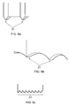
- Figure 6a illustrates engagement features 22 in the form of pyramid shaped protrusions.
- Figures 6b and 6c illustrate additional alternative configurations for the engagement features 22, including reverse arches and a saw tooth configuration.
- FIG 4a illustrates a blade 40 approaching the containment casing 2 from below.
- An inner end of a single post 20 of the retention framework 12 is illustrated supported in the honeycomb layer 18 of the intermediate layer 6.
- the post 20 is held in position by the surrounding honeycomb material.
- the honeycomb material which may for example be Nomex (RTM) honeycomb, behaves elastically for very modest loads but transitions to crush like behaviour with progressing crush displacement at near constant applied force.
- the material is generally (although not necessarily) orthotropic, exhibiting different stiffness along the plane of the material to that in the through-thickness direction. The material may also exhibit different stiffness in differing orientations within the plane of the material.
- Figure 4b illustrates the point at which the blade 40 begins to engage with the inner layer 8 of the containment casing 2.
- the softer material of the honeycomb layer 18 behind the inner layer 8 begins to crush under the force of the approaching blade 40.
- the inner layer 8 bends radially outwards, and the engagement feature 22 of the post 20 begins to penetrate the inner layer 8.
- Penetration of the engagement feature 22 may be eased by the presence of perforations in the layer 8.
- Folding, creasing and/or tearing the inner layer surface may also be seeded by the presence of perforations in the liner layer 8. Such perforations thus assist in controlling and focusing the regions of crushing. Crushing the material of the honeycomb layer 18 in the through-thickness direction causes it to become stiffer and more resistant in the in-plane direction.
- Figure 4c illustrates the effect of continued penetration of the blade 40 into the containment liner 2.
- the post 20 is wedged in place by crushed material of the honeycomb layer 18, and by the action of crushed and disturbed material further outward in the intermediate layer 6 (not shown).
- the blade 40 pushes against the wedged post 20.
- the load of the blade 40 is transmitted though the post 20, against the in-plane resistance of the spongy material (which is now stiffer in the in-plane direction following through-thickness crushing, as detailed above).
- the blade 40 is thus forced to ride up the side of the post 20 towards the outer casing layers, rather than move forward towards the front of the casing (towards the left of the Figures).
- the blade 40 may be able to penetrate the post 20, and will move forwards until it meets the next post 20, or the hook 10.
- the post 20 may yield gradually to form a hook shape, further entangling the blade 40, or it may yield cleanly. The same process takes place until the kinetic energy of the blade 40 is completely absorbed and the blade is firmly retained in the casing structure.
- the design of the individual posts 20 in the network that forms the retention structure 12 may vary along the axial length of the casing to allow for the differing modes of engagement that will be experienced by posts in different axial relation to the blades they are to contain.
- a retention framework 12 comprising circumferential rings 24 or axial or helical ribs 26 operates in a substantially similar manner to the retention framework 12 of posts 20 described above.
- the action of the retention framework 12 is to re-direct the motion of the blade 40 from the axial direction towards the radial direction, and also to reduce the speed and hence kinetic energy of the blade.
- the retention framework 12 may be integrally formed with the outer layer 4 or it may be supported solely by the intermediate layer 6.
- Figure 5a illustrates a part of a retention framework 12 which is integral with the outer layer 4 of the casing 2. This would preferably be a metallic retention framework 12, formed as part of the containment casing forging, and machined away, or separately fabricated and welded into position. It could alternatively be of another material (including composite) and be bolted or glued into position.
- Figure 5b illustrates a part of a retention framework 12 which is supported only by the intermediate layer 6 (not shown).
- the retention framework 12 may be lightly fixed in place for convenience of manufacture, but the fixing plays little or no part in the structural role of the retention framework 12.
- the retention framework 12 is illustrated in Figures 1 to 4 as extending radially substantially normally to the outer layer 4 of the containment casing 2. In alternative embodiments the retention framework 12 may be angled with respect to the normal, forwards into the gas flow (towards the left in the figures) or backwards away from the gas flow (to the right in the Figures).
- Figure 5c illustrates a retention framework element 20 that is inclined at a forward angle.
- An approaching blade meets the framework element 20 at approaching a right angle, and the framework element 20 is pressed diagonally backwards into the material of the intermediate layer 6.
- the effect of the orthotropic crush properties of the material is that the element 20 bends/rotates at the point of the blade contact following the material crush direction preference. If the though-thickness direction is stiffer (the usual situation for a honeycomb layer) then the element 20 rotates towards the vertical. The blade then drags the element 20 through the material of the intermediate layer 20 in the axial direction until the element 20 completely swings around. In this manner, the maximum kinetic energy is extracted from the blade while crushing the minimum of spongy material.
- the effectiveness of the energy absorption can be further increased by the presence of visco-elastic material filler or resin in the cells of a honeycomb structure.
- the forward angled configuration of Figure 5c is employed to best effect when the retention framework 12 is not directly connected to the outer layer 4 of the containment casing 2.
- the engagement features 22 may not come into play with a forward angled configuration. If the engagement features are employed, they generally serve to grip the inner layer 8 during the rotation and reduce axial motion.
- Figure 5d illustrates a retention framework element 20 that is inclined at a backward angle.
- An approaching blade meets the element 20 in a nearly parallel orientation, and the action of the blade/element is to crush material towards the inner layer 4.
- the blade is then pushed directly into the containment casing and becomes wedged under the base of the element near to the outer layer 4.
- the backward angled configuration of Figure 5d is employed to best effect with a relatively stiff honeycomb material in the honeycomb layer 18, adjacent the inner layer 8. Stiffness required in this layer for ice impact resistance can be a problem for containment but this configuration of the present invention enables the stiffness of this layer to be used in an effective manner to increase containment effectiveness.
- the primary action of the engagement features is to lock into the inner layer and hold the retention framework 12 in place.
- the mechanism by which the retention framework 12 is designed to operate determines to some degree to the nature of the engagement features 22 that are required. If one of the goals is to strip the metallic coating off a composite blade, then sharpness is of primary concern.
- the engagement features 22 comprise a combination of taller protrusions to penetrate the inner layer 4 and shorter ones to grind at the blade surface. Grinding or shredding the blade surface assists in breaking a composite blade into smaller, more easily contained pieces.
- the present invention provides a containment casing in which blade containment is achieved earlier in an aerofoil blade-off event than the in the present systems. A detached blade is caught more quickly and effectively, thus reducing the necessary axial length and hence the weight of the containment casing.
- the retention framework of the present invention makes more effective use of the energy absorbing properties of the intermediate layer of a containment casing, thus absorbing kinetic energy of a detached blade more efficiently, again reducing necessary weight.
Landscapes
- Engineering & Computer Science (AREA)
- Mechanical Engineering (AREA)
- General Engineering & Computer Science (AREA)
- Chemical & Material Sciences (AREA)
- Combustion & Propulsion (AREA)
- Structures Of Non-Positive Displacement Pumps (AREA)
- Heterocyclic Carbon Compounds Containing A Hetero Ring Having Nitrogen And Oxygen As The Only Ring Hetero Atoms (AREA)
Applications Claiming Priority (1)
| Application Number | Priority Date | Filing Date | Title |
|---|---|---|---|
| GBGB1003634.1A GB201003634D0 (en) | 2010-03-05 | 2010-03-05 | Containment casing |
Publications (2)
| Publication Number | Publication Date |
|---|---|
| EP2363576A2 true EP2363576A2 (de) | 2011-09-07 |
| EP2363576A3 EP2363576A3 (de) | 2017-12-06 |
Family
ID=42136492
Family Applications (1)
| Application Number | Title | Priority Date | Filing Date |
|---|---|---|---|
| EP11156446.4A Withdrawn EP2363576A3 (de) | 2010-03-05 | 2011-03-01 | Berstschutzring für ein Flugtriebwerk |
Country Status (3)
| Country | Link |
|---|---|
| US (1) | US9097139B2 (de) |
| EP (1) | EP2363576A3 (de) |
| GB (1) | GB201003634D0 (de) |
Cited By (4)
| Publication number | Priority date | Publication date | Assignee | Title |
|---|---|---|---|---|
| EP2388441A3 (de) * | 2010-05-20 | 2014-06-18 | Pratt & Whitney Canada Corp. | Gebläsegehäuse mit Abriebelementen |
| EP2767677A1 (de) * | 2013-02-13 | 2014-08-20 | Rolls-Royce plc | Rückhaltesystem für Gebläse, zugehörige Gebläseanordnung und Gasturbinentriebwerk |
| DE102013207452A1 (de) * | 2013-04-24 | 2014-11-13 | MTU Aero Engines AG | Gehäuseabschnitt einer Turbomaschinenverdichter- oder Turbomaschinenturbinenstufe |
| WO2020011617A1 (en) * | 2018-07-13 | 2020-01-16 | Rolls-Royce Plc | Fan blade containment |
Families Citing this family (12)
| Publication number | Priority date | Publication date | Assignee | Title |
|---|---|---|---|---|
| GB2501918B (en) * | 2012-05-11 | 2014-06-18 | Rolls Royce Plc | Casing |
| US20140003923A1 (en) | 2012-07-02 | 2014-01-02 | Peter Finnigan | Functionally graded composite fan containment case |
| GB201313594D0 (en) * | 2013-07-30 | 2013-09-11 | Composite Technology & Applic Ltd | Fan Track Liner |
| EP3090148B1 (de) * | 2013-12-19 | 2021-05-19 | Raytheon Technologies Corporation | Gasturbinenmotor mit energieableitungsspalt und eindämmungsschicht |
| EP3094830A4 (de) * | 2013-12-19 | 2017-11-29 | United Technologies Corporation | Energieableitender einschlussabschnitt eines kerngehäuses für einen gasturbinenmotor |
| FR3027921B1 (fr) * | 2014-10-31 | 2025-12-05 | Snecma | Alliages a base de titane presentant des proprietes mecaniques ameliorees |
| US10718352B2 (en) | 2016-07-26 | 2020-07-21 | Rolls-Royce Corporation | Multi-cellular abradable liner |
| US10550718B2 (en) | 2017-03-31 | 2020-02-04 | The Boeing Company | Gas turbine engine fan blade containment systems |
| US10487684B2 (en) | 2017-03-31 | 2019-11-26 | The Boeing Company | Gas turbine engine fan blade containment systems |
| US11434781B2 (en) * | 2018-10-16 | 2022-09-06 | General Electric Company | Frangible gas turbine engine airfoil including an internal cavity |
| US20210246807A1 (en) * | 2020-02-11 | 2021-08-12 | Pratt & Whitney Canada Corp. | Fan case for gas turbine engine and associated method of use |
| US11668205B2 (en) * | 2021-02-08 | 2023-06-06 | Honeywell International Inc. | Containment systems for engine |
Family Cites Families (17)
| Publication number | Priority date | Publication date | Assignee | Title |
|---|---|---|---|---|
| NL71631C (de) * | 1946-07-30 | |||
| GB2017228B (en) * | 1977-07-14 | 1982-05-06 | Pratt & Witney Aircraft Of Can | Shroud for a turbine rotor |
| GB2093125B (en) * | 1981-02-14 | 1984-04-18 | Rolls Royce | Gas turbine engine casing |
| US4452335A (en) * | 1982-05-03 | 1984-06-05 | United Technologies Corporation | Sound absorbing structure for a gas turbine engine |
| US4547122A (en) * | 1983-10-14 | 1985-10-15 | Aeronautical Research Associates Of Princeton, Inc. | Method of containing fractured turbine blade fragments |
| US6532857B1 (en) * | 2000-05-12 | 2003-03-18 | Ceradyne, Inc. | Ceramic array armor |
| GB0107970D0 (en) * | 2001-03-30 | 2001-05-23 | Rolls Royce Plc | A gas turbine engine blade containment assembly |
| FR2832191B1 (fr) * | 2001-11-14 | 2004-10-08 | Snecma Moteurs | Aube de soufflante a sommet fragilise |
| GB0206136D0 (en) * | 2002-03-15 | 2002-04-24 | Rolls Royce Plc | Improvements in or relating to cellular materials |
| GB0300999D0 (en) * | 2003-01-16 | 2003-02-19 | Rolls Royce Plc | A gas turbine engine blade containment assembly |
| GB2406615B (en) * | 2003-10-03 | 2005-11-30 | Rolls Royce Plc | A gas turbine engine blade containment assembly |
| GB0410778D0 (en) * | 2004-05-13 | 2004-06-16 | Rolls Royce Plc | Blade arrangement |
| FR2875850A1 (fr) * | 2004-09-30 | 2006-03-31 | Snecma Moteurs Sa | Carter de rotor de turbomachine pour la retention de corps projetes par le rotor en rotation et procede d'obtention |
| SE527732C2 (sv) | 2004-10-07 | 2006-05-23 | Volvo Aero Corp | Ett hölje för omslutande av en gasturbinkomponent |
| GB0510538D0 (en) * | 2005-05-24 | 2005-06-29 | Rolls Royce Plc | A rotor blade containment assembly for a gas turbine engine |
| GB0609632D0 (en) * | 2006-05-16 | 2006-06-28 | Rolls Royce Plc | An ice impact panel |
| US8757958B2 (en) * | 2009-08-31 | 2014-06-24 | United Technologies Corporation | Composite fan containment case |
-
2010
- 2010-03-05 GB GBGB1003634.1A patent/GB201003634D0/en not_active Ceased
-
2011
- 2011-03-01 EP EP11156446.4A patent/EP2363576A3/de not_active Withdrawn
- 2011-03-01 US US13/037,800 patent/US9097139B2/en not_active Expired - Fee Related
Non-Patent Citations (1)
| Title |
|---|
| None |
Cited By (7)
| Publication number | Priority date | Publication date | Assignee | Title |
|---|---|---|---|---|
| EP2388441A3 (de) * | 2010-05-20 | 2014-06-18 | Pratt & Whitney Canada Corp. | Gebläsegehäuse mit Abriebelementen |
| EP2767677A1 (de) * | 2013-02-13 | 2014-08-20 | Rolls-Royce plc | Rückhaltesystem für Gebläse, zugehörige Gebläseanordnung und Gasturbinentriebwerk |
| US9816510B2 (en) | 2013-02-13 | 2017-11-14 | Rolls-Royce Plc | Fan containment system |
| DE102013207452A1 (de) * | 2013-04-24 | 2014-11-13 | MTU Aero Engines AG | Gehäuseabschnitt einer Turbomaschinenverdichter- oder Turbomaschinenturbinenstufe |
| EP2796668A3 (de) * | 2013-04-24 | 2015-01-21 | MTU Aero Engines GmbH | Gehäuseabschnitt einer Turbomaschinenverdichter- oder Turbomaschinenturbinenstufe |
| US9771830B2 (en) | 2013-04-24 | 2017-09-26 | MTU Aero Engines AG | Housing section of a turbine engine compressor stage or turbine engine turbine stage |
| WO2020011617A1 (en) * | 2018-07-13 | 2020-01-16 | Rolls-Royce Plc | Fan blade containment |
Also Published As
| Publication number | Publication date |
|---|---|
| US20110217156A1 (en) | 2011-09-08 |
| US9097139B2 (en) | 2015-08-04 |
| GB201003634D0 (en) | 2010-04-21 |
| EP2363576A3 (de) | 2017-12-06 |
Similar Documents
| Publication | Publication Date | Title |
|---|---|---|
| US9097139B2 (en) | Containment casing | |
| US7766603B2 (en) | Rotor blade containment assembly for a gas turbine engine | |
| CN111287802B (zh) | 多材料前缘保护器 | |
| EP2594773B1 (de) | Ringspalthalter | |
| US10385870B2 (en) | Composite fan inlet blade containment | |
| JP4060856B2 (ja) | ケブラー層間に金属発泡体を有するファンケーシング構造 | |
| EP2458162A2 (de) | Berstschutzanordnung einer Gasturbine | |
| EP2600008B1 (de) | Turbomaschinengehäuseanordnung mit Hohlraum zum Schaufelberstschutz | |
| US11035245B2 (en) | Fan track liner | |
| EP1245791B1 (de) | Berstschutzvorrichtung für eine Gasturbine | |
| EP3351746B1 (de) | Motorgehäuse für lüfterblattrückhaltung | |
| WO2008156890A2 (en) | Composite case armor for jet engine fan case containment | |
| US20190136871A1 (en) | Composite fan case with nanoparticles | |
| US20090087309A1 (en) | Protective ring for the fan casing of a gas-turbine engine | |
| EP1087105B1 (de) | Berstschutzeinrichtung für Gasturbinen | |
| GB2488628A (en) | Turbomachine casing with energy absorbing element | |
| US20230243275A1 (en) | Composite fan case containment hook and improved forward debris capture | |
| EP2620652A1 (de) | Turbomaschinengehäuseanordnung mit Hohlraum zum Schaufelberstschutz | |
| CN111219214A (zh) | 风扇容纳 | |
| CN111075568A (zh) | 碎屑保持 | |
| US10125631B2 (en) | Fan track liner assembly | |
| CN115217629A (zh) | 用于能量吸收的轻型风扇壳体构造 | |
| EP2971525B1 (de) | Zerbrechliche hülle für eine gebläseschaufel eines gasturbinentriebwerks |
Legal Events
| Date | Code | Title | Description |
|---|---|---|---|
| PUAI | Public reference made under article 153(3) epc to a published international application that has entered the european phase |
Free format text: ORIGINAL CODE: 0009012 |
|
| AK | Designated contracting states |
Kind code of ref document: A2 Designated state(s): AL AT BE BG CH CY CZ DE DK EE ES FI FR GB GR HR HU IE IS IT LI LT LU LV MC MK MT NL NO PL PT RO RS SE SI SK SM TR |
|
| AX | Request for extension of the european patent |
Extension state: BA ME |
|
| RAP1 | Party data changed (applicant data changed or rights of an application transferred) |
Owner name: ROLLS-ROYCE PLC |
|
| PUAL | Search report despatched |
Free format text: ORIGINAL CODE: 0009013 |
|
| AK | Designated contracting states |
Kind code of ref document: A3 Designated state(s): AL AT BE BG CH CY CZ DE DK EE ES FI FR GB GR HR HU IE IS IT LI LT LU LV MC MK MT NL NO PL PT RO RS SE SI SK SM TR |
|
| AX | Request for extension of the european patent |
Extension state: BA ME |
|
| RIC1 | Information provided on ipc code assigned before grant |
Ipc: F01D 21/04 20060101AFI20171030BHEP Ipc: F02K 3/06 20060101ALI20171030BHEP |
|
| STAA | Information on the status of an ep patent application or granted ep patent |
Free format text: STATUS: REQUEST FOR EXAMINATION WAS MADE |
|
| STAA | Information on the status of an ep patent application or granted ep patent |
Free format text: STATUS: EXAMINATION IS IN PROGRESS |
|
| 17P | Request for examination filed |
Effective date: 20180606 |
|
| RBV | Designated contracting states (corrected) |
Designated state(s): AL AT BE BG CH CY CZ DE DK EE ES FI FR GB GR HR HU IE IS IT LI LT LU LV MC MK MT NL NO PL PT RO RS SE SI SK SM TR |
|
| 17Q | First examination report despatched |
Effective date: 20180706 |
|
| STAA | Information on the status of an ep patent application or granted ep patent |
Free format text: STATUS: THE APPLICATION IS DEEMED TO BE WITHDRAWN |
|
| 18D | Application deemed to be withdrawn |
Effective date: 20190117 |