EP2363685B1 - Dispositif de détection de la position avec interféromètre Fabry-Pérot confocal - Google Patents
Dispositif de détection de la position avec interféromètre Fabry-Pérot confocal Download PDFInfo
- Publication number
- EP2363685B1 EP2363685B1 EP10153054.1A EP10153054A EP2363685B1 EP 2363685 B1 EP2363685 B1 EP 2363685B1 EP 10153054 A EP10153054 A EP 10153054A EP 2363685 B1 EP2363685 B1 EP 2363685B1
- Authority
- EP
- European Patent Office
- Prior art keywords
- fabry
- perot interferometer
- mirror
- resonator
- resonator mirror
- Prior art date
- Legal status (The legal status is an assumption and is not a legal conclusion. Google has not performed a legal analysis and makes no representation as to the accuracy of the status listed.)
- Active
Links
Images


Classifications
-
- G—PHYSICS
- G01—MEASURING; TESTING
- G01B—MEASURING LENGTH, THICKNESS OR SIMILAR LINEAR DIMENSIONS; MEASURING ANGLES; MEASURING AREAS; MEASURING IRREGULARITIES OF SURFACES OR CONTOURS
- G01B9/00—Measuring instruments characterised by the use of optical techniques
- G01B9/02—Interferometers
- G01B9/02041—Interferometers characterised by particular imaging or detection techniques
- G01B9/02042—Confocal imaging
-
- G—PHYSICS
- G01—MEASURING; TESTING
- G01B—MEASURING LENGTH, THICKNESS OR SIMILAR LINEAR DIMENSIONS; MEASURING ANGLES; MEASURING AREAS; MEASURING IRREGULARITIES OF SURFACES OR CONTOURS
- G01B11/00—Measuring arrangements characterised by the use of optical techniques
- G01B11/002—Measuring arrangements characterised by the use of optical techniques for measuring two or more coordinates
-
- G—PHYSICS
- G01—MEASURING; TESTING
- G01B—MEASURING LENGTH, THICKNESS OR SIMILAR LINEAR DIMENSIONS; MEASURING ANGLES; MEASURING AREAS; MEASURING IRREGULARITIES OF SURFACES OR CONTOURS
- G01B9/00—Measuring instruments characterised by the use of optical techniques
- G01B9/02—Interferometers
- G01B9/02055—Reduction or prevention of errors; Testing; Calibration
- G01B9/02056—Passive reduction of errors
- G01B9/02061—Reduction or prevention of effects of tilts or misalignment
-
- G—PHYSICS
- G01—MEASURING; TESTING
- G01B—MEASURING LENGTH, THICKNESS OR SIMILAR LINEAR DIMENSIONS; MEASURING ANGLES; MEASURING AREAS; MEASURING IRREGULARITIES OF SURFACES OR CONTOURS
- G01B9/00—Measuring instruments characterised by the use of optical techniques
- G01B9/02—Interferometers
- G01B9/02055—Reduction or prevention of errors; Testing; Calibration
- G01B9/02075—Reduction or prevention of errors; Testing; Calibration of particular errors
- G01B9/02078—Caused by ambiguity
- G01B9/02079—Quadrature detection, i.e. detecting relatively phase-shifted signals
- G01B9/02081—Quadrature detection, i.e. detecting relatively phase-shifted signals simultaneous quadrature detection, e.g. by spatial phase shifting
-
- G—PHYSICS
- G01—MEASURING; TESTING
- G01B—MEASURING LENGTH, THICKNESS OR SIMILAR LINEAR DIMENSIONS; MEASURING ANGLES; MEASURING AREAS; MEASURING IRREGULARITIES OF SURFACES OR CONTOURS
- G01B2290/00—Aspects of interferometers not specifically covered by any group under G01B9/02
- G01B2290/25—Fabry-Perot in interferometer, e.g. etalon, cavity
-
- G—PHYSICS
- G01—MEASURING; TESTING
- G01B—MEASURING LENGTH, THICKNESS OR SIMILAR LINEAR DIMENSIONS; MEASURING ANGLES; MEASURING AREAS; MEASURING IRREGULARITIES OF SURFACES OR CONTOURS
- G01B2290/00—Aspects of interferometers not specifically covered by any group under G01B9/02
- G01B2290/45—Multiple detectors for detecting interferometer signals
Definitions
- the invention relates to a device and a method for position detection and an arrangement comprising a positioner and a device for position detection.
- EP 2 045 572 A1 is a device for position detection which uses a Fabry-Perot interferometer as a detector head.
- the interference pattern generated in the Fabry-Perot interferometer is detected by means of a detector.
- An evaluation circuit performs a quadrature evaluation of the detector signal generated by the detector.
- the device allows a very accurate position determination or path length measurement, but high demands are placed on the mirror parallelism of the Fabry-Perot interferometer resonator, which can increase the construction costs and assembly costs, limit the application area and limit the measuring range of the device.
- the publication WO 83/03010 A1 discloses a device for detecting position with a confocal Fabry-Perot interferometer.
- a confocal Fabry-Perot interferometer according to the document WO 83/03010 A1 a high measuring sensitivity and a stability against the adjustment achieved, see page 2, lines 8 - 13.
- the publication DE 40 18 998 A1 discloses a non-confocal Fabry-Perot interferometer for detecting the position of a mirrored membrane. Furthermore, it is stated in the document that an optical system for focusing and / or folding the light rays reflected back and forth in the Fabry-Perot resonator can be arranged in the Fabry-Perot resonator (column 5, lines 4-6, column 11, lines 59) - 63, column 19, lines 31-34).
- An object of the invention is therefore to be seen to provide a device and a method for position detection, which is cost-effective and can be used in a variety of applications.
- the device should be able to be integrated into a positioner and allow the positioning path generated by the positioner to be monitored.
- the device for position detection on a confocal Fabry-Perot interferometer causes the light beam circulating in the resonator of the Fabry-Perot interferometer to be independent of adjustment errors of the mirrors arranged in the beam path to a known point, typically the entry point of a light bundle fed into the Fabry-Perot interferometer (resonator) is, is focused.
- a known point typically the entry point of a light bundle fed into the Fabry-Perot interferometer (resonator) is, is focused.
- This allows a simple and inexpensive construction of the device can be achieved and there is a low adjustment effort when installing the device in their installation environment, e.g. a positioner, on.
- the device according to the invention can be used in installation environments with unfavorable conditions (vibrations, low installation space), whereby a large number of applications for the device according to the invention are made possible in the first place.
- the confocal Fabry-Perot interferometer comprises a first and a second resonator mirror and a folding mirror arranged in the beam path between the first and the second resonator mirror.
- the folding mirror is coupled to the object whose position is to be determined and allows a Autofocus, which is independent of the length of the beam path in the Fabry-Perot interferometer.
- the confocal Fabry-Perot interferometer comprises a collimator arranged in the beam path between the first and second resonator mirrors.
- the collimator serves to focus or focus the beam path in the Fabry-Perot interferometer and, in conjunction with the folding mirror, effects autofocusing, which is independent of the length of the beam path in the Fabry-Perot interferometer.
- One or more collimators may also be provided in a confused Fabry-Perot interferometer without a folding mirror.
- the first and the second resonator mirrors are arranged fixed relative to one another in a positionally fixed manner.
- a compact and robust Fabry-Perot interferometer can be realized.
- the finesse of the Fabry-Perot interferometer is less than 1.0, in particular less than 0.5.
- the interference contrast of the interference pattern generated by the Fabry-Perot interferometer behaves approximately according to a cosine function depending on the object position.
- the evaluation of a measurement signal obtained by detection of the interference pattern in an evaluation circuit is substantially facilitated and, in particular, the evaluation accuracy is increased.
- the reflectance of the first resonator mirror and the reflectance of the second resonator mirror are approximately equal. This allows a high contrast of the interference pattern and thus a high accuracy of the position determination.
- the second resonator mirror is preferably realized by an end face of an optical part arranged laterally next to the first resonator mirror.
- the first resonator mirror may be the exit surface of a core of a light guide
- the second resonator mirror may be the jacket of the light guide laterally surrounding the core.
- the device according to the invention measures a distance measurement or position determination over a measuring range of more than 10 -4 m, in particular more than 10 -3 m and, without further measures, more than 10 . 2 m can perform.
- the resolution can be over the entire measuring path in the sub-nanometer range.
- a method for position detection is defined by claim 14.
- the inventive method can be carried out in the manner already described by a structurally simple design Fabry-Perot interferometer and requires a relatively low installation and adjustment costs.
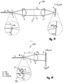
- Fig. 1 illustrates the basic structure of a Fabry-Perot interferometer 10.
- This comprises a first resonator mirror 1 and a second resonator mirror 2, which together form an optical resonator.
- the first resonator mirror 1 is partially transparent and reflects part of the incident light 3 back. The other part passes through the resonator, is reflected at the second resonator mirror 2 and partly transmitted by the first resonator mirror 1.
- the light 4 reflected by the Fabry-Perot interferometer 10 thus results from a superimposition of the light reflected by the resonator mirror 1 with the light reflected by the resonator mirror 2.
- the mirror spacing or a change in the mirror spacing can be determined.
- a displacement of, for example, the second resonator mirror 2 from the point A to the point B thus causes a change in the intensity I R of the reflected light 4, as in the lower part of the Fig. 1 is shown. Since the wavelength ⁇ of the measuring light is known, the displacement of the resonator mirror 2 from A to B and thus the change in the length of the resonator of the Fabry-Perot interferometer can be determined from a measurement of the intensity I R of the reflected light.
- Fig. 2 shows a Fabry-Perot interferometer 20, which is based on the Fig. 1 explained principle is based.
- the measuring light is guided by means of a light guide 5 to the Fabry-Perot interferometer 20.
- the light guide 5 comprises a core 5a and a jacket 5b surrounding the core 5a.
- the cladding 5b has a (slightly) smaller refractive index than the core 5a.
- the measuring light 3 emerges from the polished end of the light guide 5 and is collimated by a collimator 6 into a parallel light beam 3.
- the parallel light beam 3 is incident on the second resonator mirror 2, is reflected back from this to the collimator 6 and focused by the collimator 6 and returned to the light guide 5.
- the lens plane of the collimator 6 is for this purpose at a distance f (focal length of the collimator 6) from the exit surface of the light guide fifth
- a Fabry-Perot interferometer 20 is the first resonator mirror. 1 formed by the light exit surface of the core 5a.
- the resonator of the Fabry-Perot interferometer is thus located between the light exit surface of the core 5a and the second resonator mirror 2, which is position-variable coupled to the object (not shown).
- the Fabry-Perot interferometer 20 only functions if the light reflected back from the second resonator mirror 2 is coupled back into the core 5a of the light guide 5 after being focused by the collimator 6. The prerequisite for this is that the second resonator mirror 2 is aligned with high accuracy perpendicular to the optical axis of the Fabry-Perot interferometer 20 and this alignment is maintained even with a movement of the second resonator mirror 2. This condition is structurally difficult to meet during object movement and in any case requires a high adjustment effort. This can be seen by a simple example calculation: The diameter of the core 5a at the exit surface (i.e., the diameter of the first resonator mirror 1) is referred to as MFD (Mode Field Diameter).
- MFD Mode Field Diameter
- the tilt ⁇ of the second resonator mirror 2 with respect to its ideal position must satisfy the condition ⁇ MFD / (4f), so that the light reflected from the second resonator mirror 2 is returned to the core 5a and thus interference patterns in the reflected light 4 can occur.
- ⁇ is 0.25 mRAD.
- the second resonator mirror 2 must be mounted on an expensive precision mount and a perfectly tilt-free translational movement of the second resonator mirror 2 must be ensured. This is not possible in practice or only with great effort.
- contrast R Max - R min R Max expressed.
- the interferometer is functional only in a very narrow permitted range of the tilt angle ⁇ .
- a confocal Fabry-Perot interferometer is used to determine this Fig. 3 explained adjustment problem of a non-confocal Fabry-Perot interferometer 20 overcome.
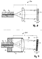
- Fig. 4 shows a non-inventive confocal Fabry-Perot interferometer 100 for position determination. The same or similar parts as in the preceding figures are designated by the same reference numerals. This in Fig. 4 shown Fabry-Perot interferometer 100 differs from that in Fig.
- Fabry-Perot interferometer 20 represented Fabry-Perot interferometer 20 characterized in that in the resonator, a second collimator 6 'is housed, which focuses the light beam generated by the first collimator 6 3 on the second resonator mirror 2. Even if this, as in Fig. 4 is shown tilted, the light reflected by the second resonator mirror 2 3 'after passing through the two collimators 6' and 6 is reflected exactly back into the core 5a of the light guide 5.
- the second collimator 6 ' may have the same focal length f as the first collimator 6.
- the confocal optics 6, 6 'thus causes the in Fig. 2 in connection with a Spiegelverkippung described problems (high equipment costs, difficult adjustment) omitted.
- the Fabry-Perot interferometer 100 has a relatively small measuring range ⁇ x max , since this is limited by the depth of focus of the focus on the second resonator mirror 2. In practice, the measuring range is limited to, for example, about 40 ⁇ m. Larger displacement paths are therefore with the in Fig. 4 Fabry-Perot interferometer 100 can not be detected.
- Fig. 5 shows an inventive embodiment of a confocal Fabry-Perot interferometer 200, with which a measuring range .DELTA.x max can be achieved, which is not limited by the focal length f, but only by structural conditions (and therefore can be very large).
- the Fabry-Perot interferometer 200 is based on the idea of the beam path of the in Fig. 4 shown Fabry-Perot interferometer 100 at the mid-perpendicular Y between the collimators 6 and 6 'too wrinkles.
- the folding causes focal points of the confocal optics always occur on stationary (stationary) mirrors, whereby the basis of Fig. 4 explained range limitation of the Fabry-Perot interferometer 100 is overcome.
- the confocal property of the interferometer optics is preserved, ie the in Fig. 5 shown Fabry-Perot interferometer is a confocal interferometer 200.
- the folding of the beam path 3, 3 'of in Fig. 4 shown confocal optics is achieved in the Fabry-Perot interferometer 200 by a flat folding mirror 7.
- the folding mirror 7 is coupled in terms of movement with the object (not shown) whose position or position change is to be determined.
- the beam path 3 of the light emerging from the light guide 5 and focused by the collimator 6 is converted by the folding mirror 7 into the beam path 3 c.
- a tilting ⁇ of the folding mirror with respect to the perpendicular to the optical axis of the Fabry-Perot interferometer 200 is assumed.
- the light beam 3c reflected by the folding mirror 7 passes through the collimator 6 (which now corresponds to the collimator 6 'in FIG Fig.
- Fig. 5 makes it clear that the confocal property of the interferometer optics is independent of the tilt angle ⁇ as long as the pixel B still strikes the end face of the light guide 5.
- the diameter of the optical waveguide 5 (ie its cladding diameter) is denoted by D.
- D the diameter of the optical waveguide 5 (ie its cladding diameter) is denoted by D.
- the condition for the maximum allowable tilt angle ⁇ is ⁇ ⁇ D / (4f).
- f 10 mm, e.g. ⁇ ⁇ 3.125 mRAD.
- the condition R 1 ⁇ R 2 should apply.
- the folding mirror 7 then preferably has a high reflectance R c greater than 0.9, in particular greater than 0.95 or R c ⁇ 1.0 (ie near 100%) in order to minimize the light intensity in the two reflections influence.
- the confocal Fabry-Perot interferometer 200 Due to the high reflectance R c of the folding mirror 7, the confocal Fabry-Perot interferometer 200 no longer functions for ⁇ ⁇ MFD / 2, ie for the case where the pixel B is as in FIG Fig. 2 falls on the exit surface of the core 5a. Because in this case, the folding mirror 7 to the second resonator mirror, whereby the contrast of the interference pattern in the reflected light 4 according to equation (1) assumes a very low value near zero.
- Fig. 6 illustrates the contrast of the interference pattern in the reflected light 4 as a function of the tilt angle ⁇ for the confocal Fabry-Perot interferometer 200.
- the curve is inverse to that in FIG Fig. 3 shown curve.
- the folding mirror 7 must be tilted or "misaligned" with a tilt angle ⁇ > MFD / (4f) compared to its "normal position” , This "misalignment condition" after Fig. 6 is much easier to assure in practice than the adjustment condition Fig. 3 ,
- Fabry-Perot interferometer 20 can be converted by simple measures into the confocal Fabry-Perot interferometer 200: For example, only the resonator mirror 2 with low reflectance R 2 is to be replaced by the folding mirror 7 with preferably high reflectance R c and the already difficult axis adjustment to avoid this mirror. By doubling the optical path length in the interferometer resonator, an additional increase in accuracy by a factor of 2 is achieved. Otherwise, to avoid repetition to the description Fig. 2 Referenced.
- FIGS. 7 and 8 show the beam path of the Fabry-Perot interferometer 200 at different tilt angles in greater detail.
- the working area is shown with ⁇ > MFD / 2.
- the pixel B is outside the core 5a.
- the beam path is shown for a very small tilt ⁇ , in which the pixel B falls within the region of the core 5a, ie ⁇ ⁇ MFD / 2. In this case, a significant loss of contrast is observed, see Fig. 6 ,
- the end of the light guide 5 via a fiber ferrule or a holder 8 and a housing 9 can be fixedly connected to the collimator 6.
- the distance L between the end of the optical fiber 5 and the folding mirror 7 is limited only by design limitations, and can be increased almost arbitrarily at a given angle ⁇ by increasing the diameter of the collimator 6 and / or by increasing the diameter D of the jacket 5b become. Without further measures, measuring ranges of more than 1 cm or even 10 cm and more are possible. In this case, during the translational movement of the folding mirror 7, a change in the tilt angle ⁇ , for example due to vibrations or the translational motion itself, can be tolerated as long as the condition MFD / 2 ⁇ ⁇ D / 2 remains satisfied. This allows use of the confocal Fabry-Perot interferometer 200 in a variety of applications.
- FIGS. 9 and 10 show further variations of the Fabry-Perot interferometer 200.
- the fiber ferrule 8 and the optional housing 9 are in the FIGS. 9 and 10 not shown.
- the effective diameter D of the jacket 5b can be increased by an optical part, eg a ring piece 5c.
- the optical ring piece 5c may be made of the same material as the cladding 5b and have a ring surface coplanar with the end face of the cladding 5b.
- the end surface of the second resonator mirror 2 (ie here of the shell 5b as well as the adjoining surface of the ring piece 5c, if present) may be provided with a spherical shape or recess. This improves the optical imaging accuracy of the confocal optics and thus the optical properties of the Fabry-Perot interferometer 200.
- Both resonator mirrors 1, 2 can also have a curved shape.
- a further variant of the confocal Fabry-Perot interferometer 200 is characterized in that the first and / or the second resonator mirrors 1, 2 are not integral with the optical waveguide 5, but are realized as one or more separate optical elements.
- the first and the second resonator mirrors 1, 2 can be realized by one or more partially transparent mirror disks, which is or are arranged in the beam path in front of the collimator 6 and is traversed by the measuring light emerging from the light conductor 5.
- a radially inner and a radially outer zone of this mirror pane may form the first and the second resonator mirrors 1, 2 and be mirrored differently, for example (in particular if the reflectance R c of the folding mirror is less than 100%). is, the reflectance of the second resonator 2 may be higher than that of the first). Furthermore, it is also possible that the interferometer resonator by suitable measures not only twice (back and forth), but 4-fold, 6-fold, etc. is traversed, in each case an increase in accuracy by the factor of Lichtwegverinrung occurs in the resonator.
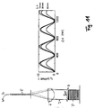
- Fig. 11 shows in the right area a diagram in which the intensity I R of the reflected light 4 in units of ⁇ Watt versus a path change ⁇ x in units of nm.
- the displacement ⁇ x of the folding mirror 7 was brought about by a piezo stack P.
- Fig. 12 shows by way of example a position detection device 300 which uses the light 4, which is reflected by a Fabry-Perot interferometer 100, 200 according to the invention, for determining the object position x.
- the position detection device 300 shown here operates on the principle of quadrature detection, which in the European patent application EP 2 045 572 A1, which is hereby incorporated by reference into the content of the present application.
- the denominator can be ignored to a first approximation and the reflectance of the Fabry-Perot interferometer fulfills the following proportionality reflectance ⁇ G 2 sin 2 ⁇ .
- G 2 ⁇ ⁇ 1 which is equivalent to reflectance ⁇ G 2 ⁇ 1 - cos 2 ⁇ ⁇ / Second
- the finesse F of the Fabry-Perot interferometer may be less than 10.0, 5.0, 1.0 or 0.5. The higher the value of the finesse F, the more difficult is a signal evaluation based on the evaluation of the curve form, since the cosine form according to equation (7) is then no longer complied with.
- At least one of the mirrors 1, 2, 7 can have a low degree of reflection.
- the reflectance of a planar polished end of a light guide 5 both in the region of the core 5a and in the region of the jacket 5b is about 4% and thus has the desired low reflectivity.
- the reflectivity levels of the resonator mirrors 1, 2 and the folding mirror 7 can also be tuned differently to each other.
- a large finesse of the Fabry-Perot interferometer 200 may also be desired, for example if the evaluation of the intensity I R is not based on the cosine shape of the intensity profile. This can be the case, for example, if no high spatial resolution is required and for the evaluation of the reflected light, for example, only the periodicity of the interference pattern, but not the curve between periodicity reference points (eg maxima) of I R is used.
- the position detection device 300 comprises an interferometer head 209, a detector arrangement 202, an evaluation circuit 204 and a light source (laser) 201. Specific examples of these components are given below.
- One of the outputs of the 1 ⁇ M coupler 208 is fed to a 2 ⁇ 2 coupler 206.
- the one output of the 2 ⁇ 2 coupler 206 is coupled into the interferometer head 209 via a SMF (Single Mode Fiber) 207.
- the interferometer head 209 may be e.g. be realized by one of the previously described confocal Fabry-Perot interferometer heads 100, 200.
- the interference light of intensity I R returned by the interferometer head 209 via the SMF 207 is fed to a detector 210.
- the detector 210 generates a measurement signal, which is fed to the evaluation circuit 204 after an optional amplification in an amplifier 220.
- a fixed wavelength laser 201 may be used and a detector signal corresponding to the one shown in FIG Fig. 11 intensity profile I R shown corresponds to or comprises only the frequency to be evaluated directly.
- a detector signal corresponding to the one shown in FIG Fig. 11 intensity profile I R shown corresponds to or comprises only the frequency to be evaluated directly.
- a position detection device 300 which performs a very accurate position determination on the basis of a so-called quadrature detection method.
- a tunable laser 201 is used as light source, with this a periodic wavelength modulation of the measurement light caused and an evaluation of the intensity I R of the confocal Fabry-Perot interferometer 100, 200 reflected light according to the quadrature principle by means of demodulation as a function of the modulation frequency of the measurement light carried out.
- demodulation as a function of the modulation frequency of the measurement light carried out.
- a quadrature evaluation can be carried out, for example, by demodulating the two time-variant components S ⁇ and S 2 ⁇ with the frequency f or the frequency 2f.
- the pre-factors 2 (P + 1) x ⁇ k and (2 (P + 1) x ⁇ k / 2) 2 of the signals S and S Q are unknown since they depend on the object location x, ie the searched value.
- an approximate value x estim for the object position is determined. Subsequently, a higher accuracy can be obtained by evaluating the quadrature detection signals S ⁇ -2 (P + 1) x estim ⁇ k sin (2 (P + 1) k 0 x) and S Q ⁇ - (2 (P + 1) x estim ⁇ k / 2) 2 cos (2 (P + 1 ) k 0 x) can be achieved by increment counting and interpolation.
- N denotes the count value of the increments of ⁇ / [8 (P + 1)] obtained during a displacement x from a reference point (zero point) x 0 .
- the approximate value x estim can be determined, for example, by measuring the maximum values max (S Q ) and max (S) of the signals S Q and S according to the equation x estim ⁇ (2 / ⁇ k) (max (S Q ) / max (S )) respectively.
- Such an evaluation of the detector signal supplied by the detector 220 may be performed by means of the in Fig. 12 Evaluation circuit 204 shown as an example.
- This includes a first lock-in amplifier 212-1 and a second lock-in amplifier 212-2, a first analog-to-digital converter 213-1, a second analog-to-digital converter 213-2, a processor 214 with access to a lookup
- the evaluation circuit 204 comprises a laser driver 216, which via a signal output of an AC generator 210 is controlled.
- the tunable laser 201 may be a DFB (Distributed)
- the laser 201 may be isolated by using a Faraday isolator such as 35 db to prevent it from being damaged or becoming unstable by reflected light.
- the demodulations of the measuring signal output by the detector 220 with the angular frequency ⁇ and the angular frequency 2 ⁇ are performed in the lock-in amplifiers 212-1 and 212-2, respectively.
- the reference inputs of the two lock-in amplifiers 212-1, 212-2 are connected to a TTL reference output of the AC generator 210.
- the measurement signal output at the output of the detector 220 is fed to the signal inputs of the two lock-in amplifiers 212-1 and 212-2.
- the first lock-in amplifier 212-1 is set to the reference angular frequency ⁇ and the second lock-in amplifier 212-2 is set to twice the reference angular frequency 2 ⁇ .
- S Q - (2 (P + 1) x ⁇ k / 2) 2 cos (2 (P + 1) k 0 x).
- the factor .delta..sub.k by the expression .delta..sub.k be approximated -2 ⁇ / ( ⁇ 0) 2, where ⁇ indicating the known Wellendorfnhub the wavelength modulation.
- the two output signals of the lock-in amplifiers 212-1, 212-2 are converted into digital signals by the analog / digital converters 213-1, 213-2.
- a first read at the output of the analogue to digital converters 213-1, 213-2 gives the displacement x in increments of ⁇ / [8 (P + 1)].
- MSB Mobile Scal Bit
- the most significant bit MSB (Most Significant Bit) at the output of each analog / digital converter is a counting input of the up / down counter.
- counter 215 may be a 24-bit counter with two counter inputs.
- a second reading of the outputs of the analog / digital converters 213-1, 213-2 is performed by the processor 214. This second readout may span the entire wordwidth of the transducer outputs.
- the interpolation can be done, for example, using a lookup table memory (LUT).
- the quadrature detection method can not necessarily be performed on the basis of the signal components S ⁇ and S 2 ⁇ , but also, for example, on the basis of the DC component S DC and one of the signal components S ⁇ or S 2 ⁇ . Because the DC component S DC is also dependent on x. In this case, one of the lock-in amplifiers 212-1, 212-2 may be omitted.
- the quadrature detection method it is always based on an evaluation of at least two signal components.
- the position detection device Due to its large number of favorable properties (high resolution, large measuring range, compactness of the interferometer head (structural dimensions less than 1 cm, weight less than 1 g), simple installation, minimal or no optical adjustment effort, the position detection device can be highly resistant to vibration since no rigid connecting lines are required ) are used in many applications and installation environments. In particular, use in extreme environments (LT, UHV, B, KV, T %) is possible.
- the position detection device can be used for monitoring the positioning movement of a positioner with a positioning accuracy in the sub-millimeter range or in the sub-micron range or in the nanometer range and even sub-nanometer range.
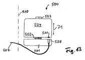
- a positioner 500 for translational movements is shown with a position detection device according to the invention in plan view.
- the positioner 500 has a first, fixed-position part 501 and a second part which is displaceable relative to the first part 501, which is referred to below as a carrier 504.
- a relative position adjustment device which can be realized, for example, by a translation axis 503 on which the carrier 504 can slide, and a piezoelectric element acting as an actuator 502.
- the direction of the translation movement is illustrated by a double arrow P1.
- the drive shown here is referred to as a so-called inertial engine or as a slip-stick drive.
- the increment of a positioning movement can not be defined exactly by controlling the drive. This means that a position determination of one arranged on the carrier 504 Positioning part in the positioner 500 can not be performed solely by monitoring the drive control (eg, a step count), but that the positioner 500 must be additionally equipped with a device that allows monitoring of the positioning position.
- a position detection device For this purpose, a position detection device according to one of the preceding embodiments is provided.
- an interferometer head 509 On the positionally fixed first part 501, an interferometer head 509 is mounted, which can be designed according to one of the preceding embodiments.
- the illuminating light emerging from the interferometer head 509 is incident on a mirror 511 mounted on the displaceable support 504, which is oriented perpendicular to the right of movement (double arrow P1) and reflects the light back to the interferometer head 503.
- the mirror 511 can be, for example, the folding mirror 7 or, in the case of in Fig. 4 also be the second resonator mirror 2 shown Fabry-Perot interferometer 100.
- the interferometer head 503 is connected via an optical fiber 507 to a detector arrangement (not shown), which may be designed according to one of the preceding embodiments and is in communication with the other components previously described (laser, evaluation circuit).
- UHV ultra high vacuum
- an optical resolution of about 1 nm or even less can be achieved.
- the step size is variable depending on the voltage for driving the piezoelectric element 502 and depending on the temperature between about 5 nm and 1 micron. Due to the high resolution of the optical position monitoring, therefore, a positioning accuracy in the range of the mechanical limits of the drive (about 5 nm) can be achieved. Particularly advantageous for many applications is the long maximum movement path, which can usually be several millimeters to one or more centimeters.
Landscapes
- Physics & Mathematics (AREA)
- General Physics & Mathematics (AREA)
- Instruments For Measurement Of Length By Optical Means (AREA)
- Length Measuring Devices By Optical Means (AREA)
Claims (14)
- Dispositif de détection de position présentant un interféromètre confocal de Fabry-Perot (100, 200) qui comporte un premier et un deuxième miroir (1, 2) de résonateur et un miroir de convolution (7) disposé dans le parcours des rayons entre le premier et le deuxième miroir (1, 2) de résonateur,
le miroir de convolution (7) étant configuré pour être accouplé mécaniquement à un objet dont la position doit être définie et
le miroir de convolution (7) étant orienté de telle sorte qu'il dévie le parcours des rayons de l'interféromètre de Fabry-Perot (200) du premier miroir de résonateur (1) sur le deuxième miroir (2) de résonateur et du deuxième miroir (2) de résonateur sur le premier miroir (1) de résonateur. - Dispositif selon la revendication 1, dans lequel l'interféromètre confocal de Fabry-Perot (100, 200) comporte un collimateur (6, 6') disposé dans le parcours des rayons entre le premier et le deuxième miroir (1, 2) de résonateur.
- Dispositif selon l'une des revendications précédentes, dans lequel le miroir de convolution (7) présente un degré de réflexion supérieur à 0,9 et en particulier supérieur à 0,95.
- Dispositif selon l'une des revendications précédentes, dans lequel le premier et le deuxième miroir (1, 2) de résonateur sont disposés en décalage radial mutuel par rapport à un axe optique de l'interféromètre de Fabry-Perot (200).
- Dispositif selon l'une des revendications précédentes, dans lequel le premier et le deuxième miroir (1, 2) de résonateur sont disposés en position fixe l'un par rapport à l'autre.
- Dispositif selon l'une des revendications précédentes, dans lequel la finesse de l'interféromètre de Fabry-Perot (100, 200) est inférieure à 1,0 et en particulier inférieure à 0,5.
- Dispositif selon l'une des revendications précédentes, dans lequel le degré de réflexion du premier miroir (1) de résonateur est inférieur à 0,15 et en particulier inférieur à 0,07 et le degré de réflexion du deuxième miroir (2) de résonateur est inférieur à 0,15 et en particulier inférieur à 0,07.
- Dispositif selon l'une des revendications précédentes, dans lequel le degré de réflexion du premier miroir (1) de résonateur et le degré de réflexion du deuxième miroir (2) de résonateur sont sensiblement de même niveau.
- Dispositif selon l'une des revendications précédentes, dans lequel le premier miroir (1) de résonateur comporte la surface de sortie de l'âme (5a) d'un conducteur (5) de lumière.
- Dispositif selon l'une des revendications précédentes, dans lequel le deuxième miroir (2) de résonateur comporte une surface d'extrémité d'une partie optique disposée latéralement à côté du premier miroir de résonateur, notamment l'enveloppe (5b) d'un conducteur (5) de lumière.
- Dispositif selon l'une des revendications précédentes, présentant une source (201) de lumière qui émet une lumière de mesure amenée à l'interféromètre de Fabry-Perot (100, 200), un détecteur (210) qui forme un signal de mesure qui dépend d'un motif d'interférence formé au moyen de l'interféromètre de Fabry-Perot (100, 200) et un circuit d'évaluation (204) qui évalue le signal de mesure.
- Dispositif selon l'une des revendications précédentes, conçu pour exécuter une mesure de distance dans une plage de mesure supérieure à 10-4 m, en particulier supérieure à 10-3 m et de manière encore plus particulière supérieure à 10-2 m.
- Ensemble constitué d'un positionneur et d'un dispositif de détection de position qui comporte le positionneur (500) et un dispositif (100, 200, 300) de détection de position selon l'une des revendications précédentes.
- Procédé de détermination de position comportant les étapes qui consistent à :former un motif d'interférence dépendant de la position d'un objet au moyen d'un interféromètre confocal de Fabry-Perot (100, 200) qui comporte un premier et un deuxième miroir (1, 2) de résonateur et un miroir de convolution (7) disposé dans le parcours des rayons entre le premier et le deuxième miroir (1, 2) de résonateur, le miroir de convolution (7) étant accouplé mécaniquement à un objet dont la position doit être déterminée et le miroir de convolution (7) étant orienté de telle sorte qu'il dévie le parcours des rayons de l'interféromètre de Fabry-Perot (200) du premier miroir (1) de résonateur jusque sur le deuxième miroir (2) de résonateur et du deuxième miroir (2) de résonateur sur le premier miroir (1) de résonateur,détecter le motif d'interférence etévaluer le signal de mesure obtenu par la détection, en vue de déterminer la position de l'objet.
Priority Applications (3)
| Application Number | Priority Date | Filing Date | Title |
|---|---|---|---|
| EP10153054.1A EP2363685B1 (fr) | 2010-02-09 | 2010-02-09 | Dispositif de détection de la position avec interféromètre Fabry-Pérot confocal |
| US13/022,901 US8773666B2 (en) | 2010-02-09 | 2011-02-08 | Device and method for acquiring position with a confocal Fabry-Perot interferometer |
| JP2011026084A JP5306386B2 (ja) | 2010-02-09 | 2011-02-09 | ファブリペロー干渉計を利用して位置を取得する装置 |
Applications Claiming Priority (1)
| Application Number | Priority Date | Filing Date | Title |
|---|---|---|---|
| EP10153054.1A EP2363685B1 (fr) | 2010-02-09 | 2010-02-09 | Dispositif de détection de la position avec interféromètre Fabry-Pérot confocal |
Publications (2)
| Publication Number | Publication Date |
|---|---|
| EP2363685A1 EP2363685A1 (fr) | 2011-09-07 |
| EP2363685B1 true EP2363685B1 (fr) | 2013-11-20 |
Family
ID=42200873
Family Applications (1)
| Application Number | Title | Priority Date | Filing Date |
|---|---|---|---|
| EP10153054.1A Active EP2363685B1 (fr) | 2010-02-09 | 2010-02-09 | Dispositif de détection de la position avec interféromètre Fabry-Pérot confocal |
Country Status (3)
| Country | Link |
|---|---|
| US (1) | US8773666B2 (fr) |
| EP (1) | EP2363685B1 (fr) |
| JP (1) | JP5306386B2 (fr) |
Cited By (1)
| Publication number | Priority date | Publication date | Assignee | Title |
|---|---|---|---|---|
| DE102018218488A1 (de) | 2018-10-29 | 2018-12-13 | Carl Zeiss Smt Gmbh | Messanordnung zur interferometrischen Absolutmessung des Abstandes zwischen zwei Komponenten in einem optischen System für die Mikrolithographie |
Families Citing this family (12)
| Publication number | Priority date | Publication date | Assignee | Title |
|---|---|---|---|---|
| DE102011056002A1 (de) * | 2011-12-02 | 2013-06-06 | Grintech Gmbh | Optisch korrigierende Mikrosonde zur Weißlicht-Interferometrie |
| DE102012217700B4 (de) * | 2012-09-28 | 2015-03-12 | Carl Zeiss Smt Gmbh | Messvorrichtung zur Messung einer Strahlposition |
| EP2806246B1 (fr) | 2013-05-24 | 2019-11-20 | Attocube Systems AG | Interféromètre à deux sources laser |
| CN104515621B (zh) * | 2014-12-24 | 2017-09-08 | 天津大学 | 基于密闭微腔气体热效应的光纤温度传感器及其制作方法 |
| DE102016103109B4 (de) | 2016-02-23 | 2018-07-26 | Björn Habrich | Vermessung einer kavität mittels interferenzspektroskopie |
| US10107614B1 (en) * | 2017-04-18 | 2018-10-23 | Quality Vision International, Inc. | Optical pen for interferometric measuring machine |
| JP7115675B2 (ja) * | 2018-02-27 | 2022-08-09 | 公立大学法人北九州市立大学 | 位置検出装置及び形状検出装置 |
| DE102018208147A1 (de) * | 2018-05-24 | 2019-11-28 | Carl Zeiss Smt Gmbh | Messanordnung zur frequenszbasierten Positionsbestimmung einer Komponente |
| CN110726366A (zh) * | 2019-10-28 | 2020-01-24 | 哈尔滨工业大学 | 光纤法布里珀罗干涉仪非线性误差修正方法 |
| EP3872444A1 (fr) * | 2020-02-25 | 2021-09-01 | ASML Netherlands B.V. | Système d'interféromètre et appareil lithographique |
| US12498275B2 (en) * | 2023-01-31 | 2025-12-16 | Fluke Corporation | Temperature measurement using fabry-pãƒâ€°rot resonator on end of optical fiber |
| DE102024201474A1 (de) * | 2024-02-19 | 2025-08-21 | Carl Zeiss Smt Gmbh | Messanordnung zur Positionsbestimmung einer bewegbaren Komponente |
Family Cites Families (16)
| Publication number | Priority date | Publication date | Assignee | Title |
|---|---|---|---|---|
| EP0101726B1 (fr) * | 1982-02-24 | 1987-01-14 | Kent Scientific and Industrial Projects Limited | Dispositif optique de detection de deplacement |
| JPH02276961A (ja) * | 1989-04-19 | 1990-11-13 | Nippon Steel Corp | レーザ超音波探傷装置 |
| DE4018998A1 (de) * | 1990-06-13 | 1992-01-02 | Dynisco Geraete Gmbh | Faseroptischer drucksensor |
| JP3304696B2 (ja) * | 1995-04-17 | 2002-07-22 | 株式会社先進材料利用ガスジェネレータ研究所 | 光学式センサ |
| JP2923779B1 (ja) * | 1998-06-18 | 1999-07-26 | 工業技術院長 | 超音波検出用光干渉装置 |
| JP2001280914A (ja) * | 2000-03-29 | 2001-10-10 | Tokyo Sokki Kenkyusho Co Ltd | 光干渉測定方法 |
| JP4113654B2 (ja) | 2000-05-10 | 2008-07-09 | 株式会社東芝 | レーザ超音波検査装置 |
| SE524828C2 (sv) * | 2002-06-06 | 2004-10-12 | Alfa Exx Ab | Resonator |
| SE526267C2 (sv) | 2003-12-05 | 2005-08-09 | Alfa Exx Ab | Optisk mätanordning |
| US7492463B2 (en) * | 2004-04-15 | 2009-02-17 | Davidson Instruments Inc. | Method and apparatus for continuous readout of Fabry-Perot fiber optic sensor |
| JP4439363B2 (ja) | 2004-09-17 | 2010-03-24 | 新日本製鐵株式会社 | レーザ超音波を利用したオンライン結晶粒径測定装置及び測定方法 |
| EP1869737B1 (fr) * | 2005-03-16 | 2021-05-12 | Davidson Instruments, Inc. | Capteur fabry-perot haute intensite |
| EP2045572B1 (fr) | 2007-10-04 | 2012-03-14 | Attocube Systems AG | Dispositif pour la détection de la position |
| US7898731B2 (en) * | 2007-11-20 | 2011-03-01 | The Regents Of The University Of California | Fiber optical parametric oscillator with high power and bandwidth |
| CN101562310B (zh) * | 2009-05-04 | 2010-09-01 | 北京国科世纪激光技术有限公司 | 被动锁模皮秒激光器 |
| JP5087186B1 (ja) * | 2009-06-19 | 2012-11-28 | ザイゴ コーポレーション | 等光路干渉計 |
-
2010
- 2010-02-09 EP EP10153054.1A patent/EP2363685B1/fr active Active
-
2011
- 2011-02-08 US US13/022,901 patent/US8773666B2/en active Active
- 2011-02-09 JP JP2011026084A patent/JP5306386B2/ja active Active
Cited By (1)
| Publication number | Priority date | Publication date | Assignee | Title |
|---|---|---|---|---|
| DE102018218488A1 (de) | 2018-10-29 | 2018-12-13 | Carl Zeiss Smt Gmbh | Messanordnung zur interferometrischen Absolutmessung des Abstandes zwischen zwei Komponenten in einem optischen System für die Mikrolithographie |
Also Published As
| Publication number | Publication date |
|---|---|
| JP2011174922A (ja) | 2011-09-08 |
| EP2363685A1 (fr) | 2011-09-07 |
| US20110211199A1 (en) | 2011-09-01 |
| JP5306386B2 (ja) | 2013-10-02 |
| US8773666B2 (en) | 2014-07-08 |
Similar Documents
| Publication | Publication Date | Title |
|---|---|---|
| EP2363685B1 (fr) | Dispositif de détection de la position avec interféromètre Fabry-Pérot confocal | |
| EP0618439B1 (fr) | Dispositif d'imagerie optique pour l'examen de milieux fortement diffusants | |
| DE19514852C2 (de) | Verfahren und Anordnung zur Beschleunigungs- und Vibrationsmessung | |
| DE69001386T2 (de) | Hochempfindliches Positionsmess-Verfahren. | |
| EP2045572B1 (fr) | Dispositif pour la détection de la position | |
| DE69122343T2 (de) | Atomkraft-Mikroskopie | |
| DE69215369T2 (de) | Positionsmessung | |
| DE2164397C3 (de) | Optoelektrische Spurvorrichtung | |
| EP0438675A2 (fr) | Capteur interférométrique pour mesurer des variations en distance d'une petite surface | |
| EP0271646B1 (fr) | Dispositif de mesure sans contact d'une distance d'une surface, en particulier pour palper un contour d'une surface d'une pièce d'oeuvre le long d'une trajectoire de mesure | |
| EP0876595A1 (fr) | Appareil interferometrique de faible coherence | |
| EP3608625B1 (fr) | Système de mesure oct | |
| WO2010006764A2 (fr) | Interféromètre multi-longueurs d'ondes à fibres optiques pour la mesure absolue de distances et topologies de surfaces pour de grandes distances de travail | |
| DE69418821T2 (de) | Kombiniertes Nahfeld- und Atomkraftrastermikroskop | |
| EP1258767A1 (fr) | Microscope et procédé d'utilisation d'un microscope | |
| EP1262734A1 (fr) | Appareil pour mesurer un objet sans contact, en particulier pour la mesure de distances et/ou de vibrations | |
| DE60211388T2 (de) | Sensor mit kantilever und optischem resonator | |
| DE3313861C2 (de) | Halterung für ein Paar von Planspiegeln und eine Kugel in einer Interferometer-Längenmeßeinrichtung | |
| EP1174680A2 (fr) | Dispositif pour varier la longueur du trajet optique d' une onde électromagnétique | |
| DE10039094C1 (de) | Vorrichtung zur quantitativen hochauflösenden Messung von Abständen, Kräften, Elastizitäten, Drücken und Beschleunigungen | |
| DE19713746C2 (de) | Sensor für gleichzeitige Rasterkraftmikroskopie und optische Nahfeldmikroskopie | |
| DE102006060584B4 (de) | Verfahren und Vorrichtung zur Messung von Verschiebungen und/oder einer Geometrie von Mikrostrukturen | |
| DE4233399C2 (de) | Kraftmikroskop | |
| DE69413703T2 (de) | Inspektionsvorrichtung für optische wellenleiter | |
| DE102008057100A1 (de) | Untersuchungseinheit für nahfeldoptische Mikroskopie |
Legal Events
| Date | Code | Title | Description |
|---|---|---|---|
| PUAI | Public reference made under article 153(3) epc to a published international application that has entered the european phase |
Free format text: ORIGINAL CODE: 0009012 |
|
| AK | Designated contracting states |
Kind code of ref document: A1 Designated state(s): AT BE BG CH CY CZ DE DK EE ES FI FR GB GR HR HU IE IS IT LI LT LU LV MC MK MT NL NO PL PT RO SE SI SK SM TR |
|
| AX | Request for extension of the european patent |
Extension state: AL BA RS |
|
| 17P | Request for examination filed |
Effective date: 20120307 |
|
| 17Q | First examination report despatched |
Effective date: 20120809 |
|
| GRAP | Despatch of communication of intention to grant a patent |
Free format text: ORIGINAL CODE: EPIDOSNIGR1 |
|
| RIN1 | Information on inventor provided before grant (corrected) |
Inventor name: BRAUN, PIERRE-FRANCOIS Inventor name: KARRAI, KHALED |
|
| GRAP | Despatch of communication of intention to grant a patent |
Free format text: ORIGINAL CODE: EPIDOSNIGR1 |
|
| INTG | Intention to grant announced |
Effective date: 20130620 |
|
| GRAS | Grant fee paid |
Free format text: ORIGINAL CODE: EPIDOSNIGR3 |
|
| GRAA | (expected) grant |
Free format text: ORIGINAL CODE: 0009210 |
|
| AK | Designated contracting states |
Kind code of ref document: B1 Designated state(s): AT BE BG CH CY CZ DE DK EE ES FI FR GB GR HR HU IE IS IT LI LT LU LV MC MK MT NL NO PL PT RO SE SI SK SM TR |
|
| REG | Reference to a national code |
Ref country code: GB Ref legal event code: FG4D Free format text: NOT ENGLISH |
|
| REG | Reference to a national code |
Ref country code: CH Ref legal event code: EP |
|
| REG | Reference to a national code |
Ref country code: AT Ref legal event code: REF Ref document number: 641894 Country of ref document: AT Kind code of ref document: T Effective date: 20131215 |
|
| REG | Reference to a national code |
Ref country code: IE Ref legal event code: FG4D Free format text: LANGUAGE OF EP DOCUMENT: GERMAN |
|
| REG | Reference to a national code |
Ref country code: DE Ref legal event code: R096 Ref document number: 502010005404 Country of ref document: DE Effective date: 20140116 |
|
| REG | Reference to a national code |
Ref country code: CH Ref legal event code: NV Representative=s name: SERVOPATENT GMBH, CH |
|
| REG | Reference to a national code |
Ref country code: NL Ref legal event code: VDEP Effective date: 20131120 |
|
| REG | Reference to a national code |
Ref country code: LT Ref legal event code: MG4D |
|
| PG25 | Lapsed in a contracting state [announced via postgrant information from national office to epo] |
Ref country code: NO Free format text: LAPSE BECAUSE OF FAILURE TO SUBMIT A TRANSLATION OF THE DESCRIPTION OR TO PAY THE FEE WITHIN THE PRESCRIBED TIME-LIMIT Effective date: 20140220 Ref country code: IS Free format text: LAPSE BECAUSE OF FAILURE TO SUBMIT A TRANSLATION OF THE DESCRIPTION OR TO PAY THE FEE WITHIN THE PRESCRIBED TIME-LIMIT Effective date: 20140320 Ref country code: NL Free format text: LAPSE BECAUSE OF FAILURE TO SUBMIT A TRANSLATION OF THE DESCRIPTION OR TO PAY THE FEE WITHIN THE PRESCRIBED TIME-LIMIT Effective date: 20131120 Ref country code: SE Free format text: LAPSE BECAUSE OF FAILURE TO SUBMIT A TRANSLATION OF THE DESCRIPTION OR TO PAY THE FEE WITHIN THE PRESCRIBED TIME-LIMIT Effective date: 20131120 Ref country code: LT Free format text: LAPSE BECAUSE OF FAILURE TO SUBMIT A TRANSLATION OF THE DESCRIPTION OR TO PAY THE FEE WITHIN THE PRESCRIBED TIME-LIMIT Effective date: 20131120 Ref country code: FI Free format text: LAPSE BECAUSE OF FAILURE TO SUBMIT A TRANSLATION OF THE DESCRIPTION OR TO PAY THE FEE WITHIN THE PRESCRIBED TIME-LIMIT Effective date: 20131120 Ref country code: HR Free format text: LAPSE BECAUSE OF FAILURE TO SUBMIT A TRANSLATION OF THE DESCRIPTION OR TO PAY THE FEE WITHIN THE PRESCRIBED TIME-LIMIT Effective date: 20131120 |
|
| PG25 | Lapsed in a contracting state [announced via postgrant information from national office to epo] |
Ref country code: LV Free format text: LAPSE BECAUSE OF FAILURE TO SUBMIT A TRANSLATION OF THE DESCRIPTION OR TO PAY THE FEE WITHIN THE PRESCRIBED TIME-LIMIT Effective date: 20131120 Ref country code: ES Free format text: LAPSE BECAUSE OF FAILURE TO SUBMIT A TRANSLATION OF THE DESCRIPTION OR TO PAY THE FEE WITHIN THE PRESCRIBED TIME-LIMIT Effective date: 20131120 |
|
| PG25 | Lapsed in a contracting state [announced via postgrant information from national office to epo] |
Ref country code: PT Free format text: LAPSE BECAUSE OF FAILURE TO SUBMIT A TRANSLATION OF THE DESCRIPTION OR TO PAY THE FEE WITHIN THE PRESCRIBED TIME-LIMIT Effective date: 20140320 |
|
| PG25 | Lapsed in a contracting state [announced via postgrant information from national office to epo] |
Ref country code: EE Free format text: LAPSE BECAUSE OF FAILURE TO SUBMIT A TRANSLATION OF THE DESCRIPTION OR TO PAY THE FEE WITHIN THE PRESCRIBED TIME-LIMIT Effective date: 20131120 |
|
| REG | Reference to a national code |
Ref country code: DE Ref legal event code: R097 Ref document number: 502010005404 Country of ref document: DE |
|
| PG25 | Lapsed in a contracting state [announced via postgrant information from national office to epo] |
Ref country code: RO Free format text: LAPSE BECAUSE OF FAILURE TO SUBMIT A TRANSLATION OF THE DESCRIPTION OR TO PAY THE FEE WITHIN THE PRESCRIBED TIME-LIMIT Effective date: 20131120 Ref country code: PL Free format text: LAPSE BECAUSE OF FAILURE TO SUBMIT A TRANSLATION OF THE DESCRIPTION OR TO PAY THE FEE WITHIN THE PRESCRIBED TIME-LIMIT Effective date: 20131120 Ref country code: CZ Free format text: LAPSE BECAUSE OF FAILURE TO SUBMIT A TRANSLATION OF THE DESCRIPTION OR TO PAY THE FEE WITHIN THE PRESCRIBED TIME-LIMIT Effective date: 20131120 Ref country code: SK Free format text: LAPSE BECAUSE OF FAILURE TO SUBMIT A TRANSLATION OF THE DESCRIPTION OR TO PAY THE FEE WITHIN THE PRESCRIBED TIME-LIMIT Effective date: 20131120 |
|
| BERE | Be: lapsed |
Owner name: ATTOCUBE SYSTEMS A.G. Effective date: 20140228 |
|
| PLBE | No opposition filed within time limit |
Free format text: ORIGINAL CODE: 0009261 |
|
| STAA | Information on the status of an ep patent application or granted ep patent |
Free format text: STATUS: NO OPPOSITION FILED WITHIN TIME LIMIT |
|
| PG25 | Lapsed in a contracting state [announced via postgrant information from national office to epo] |
Ref country code: MC Free format text: LAPSE BECAUSE OF FAILURE TO SUBMIT A TRANSLATION OF THE DESCRIPTION OR TO PAY THE FEE WITHIN THE PRESCRIBED TIME-LIMIT Effective date: 20131120 Ref country code: LU Free format text: LAPSE BECAUSE OF FAILURE TO SUBMIT A TRANSLATION OF THE DESCRIPTION OR TO PAY THE FEE WITHIN THE PRESCRIBED TIME-LIMIT Effective date: 20140209 Ref country code: DK Free format text: LAPSE BECAUSE OF FAILURE TO SUBMIT A TRANSLATION OF THE DESCRIPTION OR TO PAY THE FEE WITHIN THE PRESCRIBED TIME-LIMIT Effective date: 20131120 |
|
| 26N | No opposition filed |
Effective date: 20140821 |
|
| REG | Reference to a national code |
Ref country code: IE Ref legal event code: MM4A |
|
| REG | Reference to a national code |
Ref country code: DE Ref legal event code: R097 Ref document number: 502010005404 Country of ref document: DE Effective date: 20140821 |
|
| PG25 | Lapsed in a contracting state [announced via postgrant information from national office to epo] |
Ref country code: IE Free format text: LAPSE BECAUSE OF NON-PAYMENT OF DUE FEES Effective date: 20140209 Ref country code: BE Free format text: LAPSE BECAUSE OF NON-PAYMENT OF DUE FEES Effective date: 20140228 |
|
| PG25 | Lapsed in a contracting state [announced via postgrant information from national office to epo] |
Ref country code: SI Free format text: LAPSE BECAUSE OF FAILURE TO SUBMIT A TRANSLATION OF THE DESCRIPTION OR TO PAY THE FEE WITHIN THE PRESCRIBED TIME-LIMIT Effective date: 20131120 |
|
| PG25 | Lapsed in a contracting state [announced via postgrant information from national office to epo] |
Ref country code: IT Free format text: LAPSE BECAUSE OF FAILURE TO SUBMIT A TRANSLATION OF THE DESCRIPTION OR TO PAY THE FEE WITHIN THE PRESCRIBED TIME-LIMIT Effective date: 20131120 |
|
| REG | Reference to a national code |
Ref country code: FR Ref legal event code: PLFP Year of fee payment: 7 |
|
| PG25 | Lapsed in a contracting state [announced via postgrant information from national office to epo] |
Ref country code: MT Free format text: LAPSE BECAUSE OF FAILURE TO SUBMIT A TRANSLATION OF THE DESCRIPTION OR TO PAY THE FEE WITHIN THE PRESCRIBED TIME-LIMIT Effective date: 20131120 |
|
| REG | Reference to a national code |
Ref country code: AT Ref legal event code: MM01 Ref document number: 641894 Country of ref document: AT Kind code of ref document: T Effective date: 20150209 |
|
| PG25 | Lapsed in a contracting state [announced via postgrant information from national office to epo] |
Ref country code: SM Free format text: LAPSE BECAUSE OF FAILURE TO SUBMIT A TRANSLATION OF THE DESCRIPTION OR TO PAY THE FEE WITHIN THE PRESCRIBED TIME-LIMIT Effective date: 20131120 |
|
| PG25 | Lapsed in a contracting state [announced via postgrant information from national office to epo] |
Ref country code: AT Free format text: LAPSE BECAUSE OF NON-PAYMENT OF DUE FEES Effective date: 20150209 |
|
| PG25 | Lapsed in a contracting state [announced via postgrant information from national office to epo] |
Ref country code: BG Free format text: LAPSE BECAUSE OF FAILURE TO SUBMIT A TRANSLATION OF THE DESCRIPTION OR TO PAY THE FEE WITHIN THE PRESCRIBED TIME-LIMIT Effective date: 20131120 Ref country code: GR Free format text: LAPSE BECAUSE OF FAILURE TO SUBMIT A TRANSLATION OF THE DESCRIPTION OR TO PAY THE FEE WITHIN THE PRESCRIBED TIME-LIMIT Effective date: 20140221 Ref country code: CY Free format text: LAPSE BECAUSE OF FAILURE TO SUBMIT A TRANSLATION OF THE DESCRIPTION OR TO PAY THE FEE WITHIN THE PRESCRIBED TIME-LIMIT Effective date: 20131120 |
|
| PG25 | Lapsed in a contracting state [announced via postgrant information from national office to epo] |
Ref country code: TR Free format text: LAPSE BECAUSE OF FAILURE TO SUBMIT A TRANSLATION OF THE DESCRIPTION OR TO PAY THE FEE WITHIN THE PRESCRIBED TIME-LIMIT Effective date: 20131120 Ref country code: HU Free format text: LAPSE BECAUSE OF FAILURE TO SUBMIT A TRANSLATION OF THE DESCRIPTION OR TO PAY THE FEE WITHIN THE PRESCRIBED TIME-LIMIT; INVALID AB INITIO Effective date: 20100209 |
|
| REG | Reference to a national code |
Ref country code: FR Ref legal event code: PLFP Year of fee payment: 8 |
|
| REG | Reference to a national code |
Ref country code: FR Ref legal event code: PLFP Year of fee payment: 9 |
|
| PG25 | Lapsed in a contracting state [announced via postgrant information from national office to epo] |
Ref country code: MK Free format text: LAPSE BECAUSE OF FAILURE TO SUBMIT A TRANSLATION OF THE DESCRIPTION OR TO PAY THE FEE WITHIN THE PRESCRIBED TIME-LIMIT Effective date: 20131120 |
|
| REG | Reference to a national code |
Ref country code: CH Ref legal event code: PCAR Free format text: NEW ADDRESS: WANNERSTRASSE 9/1, 8045 ZUERICH (CH) |
|
| PGFP | Annual fee paid to national office [announced via postgrant information from national office to epo] |
Ref country code: CH Payment date: 20250301 Year of fee payment: 16 |
|
| REG | Reference to a national code |
Ref country code: CH Ref legal event code: U11 Free format text: ST27 STATUS EVENT CODE: U-0-0-U10-U11 (AS PROVIDED BY THE NATIONAL OFFICE) Effective date: 20260301 |
|
| PGFP | Annual fee paid to national office [announced via postgrant information from national office to epo] |
Ref country code: GB Payment date: 20260219 Year of fee payment: 17 |
|
| PGFP | Annual fee paid to national office [announced via postgrant information from national office to epo] |
Ref country code: DE Payment date: 20260218 Year of fee payment: 17 |
|
| PGFP | Annual fee paid to national office [announced via postgrant information from national office to epo] |
Ref country code: FR Payment date: 20260218 Year of fee payment: 17 |