EP1174680A2 - Dispositif pour varier la longueur du trajet optique d' une onde électromagnétique - Google Patents
Dispositif pour varier la longueur du trajet optique d' une onde électromagnétique Download PDFInfo
- Publication number
- EP1174680A2 EP1174680A2 EP01117591A EP01117591A EP1174680A2 EP 1174680 A2 EP1174680 A2 EP 1174680A2 EP 01117591 A EP01117591 A EP 01117591A EP 01117591 A EP01117591 A EP 01117591A EP 1174680 A2 EP1174680 A2 EP 1174680A2
- Authority
- EP
- European Patent Office
- Prior art keywords
- waveguide
- core
- change
- sections
- length
- Prior art date
- Legal status (The legal status is an assumption and is not a legal conclusion. Google has not performed a legal analysis and makes no representation as to the accuracy of the status listed.)
- Withdrawn
Links
- 230000008859 change Effects 0.000 claims abstract description 38
- 239000000835 fiber Substances 0.000 claims description 45
- 239000010453 quartz Substances 0.000 claims description 37
- VYPSYNLAJGMNEJ-UHFFFAOYSA-N silicon dioxide Inorganic materials O=[Si]=O VYPSYNLAJGMNEJ-UHFFFAOYSA-N 0.000 claims description 37
- 238000004804 winding Methods 0.000 claims description 9
- 238000012014 optical coherence tomography Methods 0.000 claims description 8
- 238000006073 displacement reaction Methods 0.000 claims description 5
- 230000000694 effects Effects 0.000 claims description 5
- 238000009615 fourier-transform spectroscopy Methods 0.000 claims description 4
- 238000013016 damping Methods 0.000 claims description 3
- 230000008878 coupling Effects 0.000 description 12
- 238000010168 coupling process Methods 0.000 description 12
- 238000005859 coupling reaction Methods 0.000 description 12
- 230000003287 optical effect Effects 0.000 description 7
- 239000004020 conductor Substances 0.000 description 4
- 238000005259 measurement Methods 0.000 description 2
- 239000013307 optical fiber Substances 0.000 description 2
- 230000036961 partial effect Effects 0.000 description 2
- 230000001681 protective effect Effects 0.000 description 2
- 230000009471 action Effects 0.000 description 1
- 239000011149 active material Substances 0.000 description 1
- 230000002411 adverse Effects 0.000 description 1
- 238000010276 construction Methods 0.000 description 1
- 230000001419 dependent effect Effects 0.000 description 1
- 238000001514 detection method Methods 0.000 description 1
- 230000007613 environmental effect Effects 0.000 description 1
- 238000011156 evaluation Methods 0.000 description 1
- 238000002839 fiber optic waveguide Methods 0.000 description 1
- 239000003365 glass fiber Substances 0.000 description 1
- 230000001939 inductive effect Effects 0.000 description 1
- 239000007924 injection Substances 0.000 description 1
- 238000002347 injection Methods 0.000 description 1
- 238000004519 manufacturing process Methods 0.000 description 1
- 239000000463 material Substances 0.000 description 1
- 230000010355 oscillation Effects 0.000 description 1
- 230000010363 phase shift Effects 0.000 description 1
- 229920000642 polymer Polymers 0.000 description 1
- 230000004044 response Effects 0.000 description 1
- 239000007787 solid Substances 0.000 description 1
- 238000001228 spectrum Methods 0.000 description 1
- 230000003068 static effect Effects 0.000 description 1
- 230000002123 temporal effect Effects 0.000 description 1
- 230000036962 time dependent Effects 0.000 description 1
Images

Classifications
-
- G—PHYSICS
- G01—MEASURING; TESTING
- G01D—MEASURING NOT SPECIALLY ADAPTED FOR A SPECIFIC VARIABLE; ARRANGEMENTS FOR MEASURING TWO OR MORE VARIABLES NOT COVERED IN A SINGLE OTHER SUBCLASS; TARIFF METERING APPARATUS; MEASURING OR TESTING NOT OTHERWISE PROVIDED FOR
- G01D5/00—Mechanical means for transferring the output of a sensing member; Means for converting the output of a sensing member to another variable where the form or nature of the sensing member does not constrain the means for converting; Transducers not specially adapted for a specific variable
- G01D5/26—Mechanical means for transferring the output of a sensing member; Means for converting the output of a sensing member to another variable where the form or nature of the sensing member does not constrain the means for converting; Transducers not specially adapted for a specific variable characterised by optical transfer means, i.e. using infrared, visible, or ultraviolet light
- G01D5/32—Mechanical means for transferring the output of a sensing member; Means for converting the output of a sensing member to another variable where the form or nature of the sensing member does not constrain the means for converting; Transducers not specially adapted for a specific variable characterised by optical transfer means, i.e. using infrared, visible, or ultraviolet light with attenuation or whole or partial obturation of beams of light
- G01D5/34—Mechanical means for transferring the output of a sensing member; Means for converting the output of a sensing member to another variable where the form or nature of the sensing member does not constrain the means for converting; Transducers not specially adapted for a specific variable characterised by optical transfer means, i.e. using infrared, visible, or ultraviolet light with attenuation or whole or partial obturation of beams of light the beams of light being detected by photocells
- G01D5/353—Mechanical means for transferring the output of a sensing member; Means for converting the output of a sensing member to another variable where the form or nature of the sensing member does not constrain the means for converting; Transducers not specially adapted for a specific variable characterised by optical transfer means, i.e. using infrared, visible, or ultraviolet light with attenuation or whole or partial obturation of beams of light the beams of light being detected by photocells influencing the transmission properties of an optical fibre
- G01D5/35303—Mechanical means for transferring the output of a sensing member; Means for converting the output of a sensing member to another variable where the form or nature of the sensing member does not constrain the means for converting; Transducers not specially adapted for a specific variable characterised by optical transfer means, i.e. using infrared, visible, or ultraviolet light with attenuation or whole or partial obturation of beams of light the beams of light being detected by photocells influencing the transmission properties of an optical fibre using a reference fibre, e.g. interferometric devices
Definitions
- the invention relates to a device for changing the length of the Running distance of an electromagnetic wave according to the in the preamble of claim 1 specified features.
- Devices of this type are known and are used to change the runtime an electromagnetic wave, in particular a light beam, to generate a Doppler shift, to generate a time-dependent Spectrum or the like.
- OCT optical coherence tomography
- fiber gyroscopes or also used in Fourier transform spectroscopy.
- Such devices can be used wherever it is required, the optical To change the path length of a beam path.
- Known devices either work with mirror arrangements or, like the ones in question here, with a waveguide, especially a quartz fiber, the length of which is stretched by the conductor or the fiber is changed.
- U.S. Patent 5,321,501 there is an apparatus for optical coherence tomography described, which includes such a device.
- This device has a fiber optic waveguide that wraps around a piezo element is wound, which expands when an electrical voltage is applied, which also causes the waveguide wound on it to expand the path of the light changes.
- a disadvantage of those described there Device is that due to the piezoelectric Expansion of the fiber optic conductor was not defined and multi-axis, which causes stress-induced birefringence can occur, which leads to falsification of the results. About that In addition, the device described there tends in dynamic operation to partial vibrations, which questions their usefulness.
- a similar chamfer modulator is known from JP 600 63 517, in which Piezoelectric elements on four sides of a substantially cylindrical one Body are arranged, which can be controlled at the same time. at this arrangement can achieve a comparatively high elongation are, however, the stretching is undefined and multiaxial, so that you also have the aforementioned disadvantages.
- US Pat. No. 5,867,268 discloses an apparatus for optical coherence tomography described in which an optical waveguide spirally on a disc-shaped Piezo element is glued on.
- a device is known from US Pat. No. 5,029,978 known in which the optical fiber in a piezoelectric active polymer are cast.
- US Pat. No. 5,135,295 describes to coat an optical fiber with a piezoelectrically active material, to stretch the fiber almost immediately in this way can.
- the object of the invention is to design a generic device so that the aforementioned Disadvantages are largely avoided and that in particular a defined path length change can be achieved, which may can also be measured.
- the basic idea of the present invention is to stretch the Only bring the waveguide where it is essentially straight runs to avoid a defined change in length to ensure disadvantages mentioned above.
- the waveguide will thereby wound on a divided multi-part core and the change in length by changing the distance between the core parts causes. In the simplest form, this can be done by the Core is formed from two halves, the distance between which can be changed is. This way it is possible to insert the waveguide in its rectilinear sections between these halves almost exclusively to apply tensile forces to a defined change in length to achieve. Practically any drive for stretching can be used be used. A detection of the change in length is also without further possible in which the distance change of the halves to each other is determined.
- the halves or the core parts In principle, it is conceivable for the halves or the core parts to be in relation to one another to pivot about an axis, thereby changing the position bring about. However, the change in position is preferred by Linear displacement of the core parts to each other take place, since this ensures can be that with a suitable arrangement of the turns as well as design of the cores exclusively tensile stresses on the Waveguides are applied. This can otherwise be disadvantageous stress-induced birefringence can be avoided. In principle, it does not matter whether both core parts or also several core parts are moved towards each other or whether only one core part is moved by the other or the other core parts.
- the stretch can by a piezo element, by a stack of piezo elements, electromagnetic, electromotive (with an eccentric drive) or another suitable drive without the leave principle according to the invention.
- the core part In order to generate predominantly tensile stresses in the waveguide, it is expedient, the core part to be moved or to be moved Store core parts accordingly.
- a Linear guide e.g. B. a roller bearing guide
- a solid-state joint can also advantageously be used here are, for example, a parallel leaf spring guide.
- the core has sections, lengthways of which the waveguide is curved and other sections along which the Waveguide runs essentially straight and the waveguide in the areas in which it is curved, on the corresponding one Core section glued or in some other suitable material or is non-positively attached to ensure that in these areas little or no relative movement between core and Waveguide occurs, but only in the areas where the waveguide runs straight.
- the waveguide should preferably not immediately or if only with as little as possible Friction coefficients are applied in order to avoid any transverse forces in addition to the tensile stresses initiate.
- such support brings in Essentially rectilinear sections of the waveguide considerable advantages, especially in dynamic operation, because then an uncontrolled oscillation of the waveguide in these areas can be prevented.
- a piezo element can preferably also be used or a stack of piezo elements can be used as the drive, since that nonlinear behavior either through appropriate regulation or can be compensated for by measurement.
- a sensor parallel to the drive, e.g. B. between the mutually movable core sections, a sensor provide, preferably a capacitive transducer. But it can also ever any other transducers depending on the type and extent of the strains, e.g. Strain gauges, inductive sensors or the like be used.
- Quartz fiber can advantageously be used as the waveguide, depending on Requirements of protective or non-protective quartz fiber Can be used. Such quartz fibers are inexpensive to manufacture and can be stretched up to 10% elastically, so that even at low Number of turns large changes in length can be achieved. Prefers the winding takes place in one layer, but multi-layer windings can also be used be provided if it is ensured that the waveguide is in the area its curved sections is set to multi-axis voltage injections to avoid.
- the device preferably has a control system which is a function of the the signal emitted by the displacement transducer (measuring transducer) is the distance of the core parts determining drive element controls so that the change in length the running route can be changed in a targeted manner, in particular also depending currently. In this way, the change in length according to a predetermined Speed or path profile.
- a preferred application of the device according to the invention is in the Fourier transform spectroscopy, in the sample branch. It can also Device as a phase modulator either in the reference and / or in the sample branch an interferometer used in optical coherence tomography is used.
- Such an interferometric measuring arrangement can have, for example, two coupling devices, one in a first Coupling device the light waves coming from a light source into one Sample arm and be coupled into a reference arm and in the second Coupling device the light waves coming from the reference arm and the light waves coming from the sample arm are superimposed and at least one, preferably two detectors are supplied, which the optical interference convert into an electrical signal.
- the reference arm by one extending between the coupling devices Fiber conductor formed.
- the sample arm preferably has at least two Fiber conductors on both sides of the first coupling device extend.
- Such an arrangement is particularly bright and because of its Construction (guidance of the light waves almost exclusively in fiber guides) largely insensitive to external environmental influences.
- the device according to the invention is advantageous both in Sample branch and also used in the reference branch of an interferometer, where a device for dynamic path length change of light and the other serves for the static setting of the working point.
- both devices thermally, for example, by means of a heat-conducting common support frame be connected, thereby ensuring that even with changing Operating temperature no outward shift of the Working point or a corresponding shift in the other branch takes place, which compensates for this.
- the device according to the invention can change length in many areas are used, for example for field strength measurement using the electrostrictive effect.
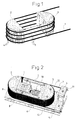
- the waveguide 1 illustrates a waveguide 1 in Shape of a quartz fiber wound on a core consisting of parts 2 and 3, whose distance a can be changed by means of a drive, not shown is.
- the core parts 2 and 3 each form half of a cylindrical body, so that the waveguide 1 has curved sections 4 with which it is on Core rests and substantially straight sections 5, the are formed between the core parts 2 and 3.
- the waveguide 1 is included its ends and in addition in the area of the curved sections 4 connected to the core parts 2 and 3 so that by changing the Distance a only the straight sections 5 of the waveguide 1 can be loaded or relieved of tension.
- the waveguide is under tension wound up the core, ensuring that the straight sections 5 are always excited.
- the waveguide 1 follows this movement by stretching the straight-line sections 5.
- the Distance change ⁇ a multiplied by twice the number of windings (Doubling since the straight sections 5 twice in each winding are present), in this case eight times the change in distance Corresponds to ⁇ a.
- a large number of windings can be wound onto the core, so that there is already a very considerable change in length of the waveguide 1 then results if the distance between the core parts 2 and 3 is only slight changes.
- a change in the distance is sufficient Core parts 2 and 3 of 45 ⁇ if the distance a is 80 mm and 23 windings are provided. If you use a core diameter of 30 mm, this results in a total length of the waveguide 1 of 5.50 m.
- Fig. 2 is such a device built on a base plate 6.
- A is firmly connected to the base plate Core part 3, whereas the left core part 2 in FIG. 2 has a not shown Solid body joint is linearly displaceable on the base plate 6.
- the Core parts 2 and 3 have, as in the basic illustration according to FIG. 1, semi-cylindrical Forms, however, the core part 3 is a U-shaped in plan view Guide part 7 of the rectilinear sections 5 of the form of a Quartz fiber trained waveguide 1 leads.
- This guide part 7 lies with little play on these sections 5 and should prevent them in dynamic operation swing transverse to the direction of the change in distance.
- the Guide part 7 can, however, also be subject to friction on the straight-line sections the quartz fiber in order to specifically achieve increased damping.
- the core parts 3 and 7 are by means of screws, not shown, on the Base plate 6 attached.
- a cuboid part closes on the left half-cylindrical core part 2 8 on, which protrudes inside the guide part 7 and part of a capacitive Path measuring device between the movable component 8 and a fixed one Component 9 is.
- the piezoelectric element 10 can consist of several in succession and / or individual elements arranged in parallel.
- the quartz fiber 1 is wound in one layer over the core 2, 3, 7, the Quartz fiber 1 in the region of its curved sections 4 on the core parts 2 and 3 is tight, whereas in the area of the straight sections 5 a loose System on the sides of the guide part 7, so that the quartz fiber in stretch these straight sections 5 freely and contract them again can.
- the quartz fiber 1 is fixed at the end, by means of two clamping plates 11, which are connected to the base plate 6. The winding up takes place under tension.
- the piezoelectric element 10 As soon as the piezoelectric element 10 is subjected to voltage, it expands this in the axial direction, whereby the core parts 2 and 3 away from each other be moved (distance change ⁇ a), causing an expansion of the straight line Sections 5 of the quartz fiber takes place. Since the movement, i.e. H. the temporal Course of the change in distance is detected by means of the path measuring device 8, 9, can the piezoelectric over a control not described in detail here Element 10 are controlled so that a predetermined path or Speed profile is generated. In any case, the change in distance ⁇ a and thus the change in length of the quartz fiber 1 can be determined exactly.
- the movable part 3 is reset on the one hand via the spring action of the solid-state joint and on the other hand via the restoring force of the quartz fiber 1.
- the device is particularly suitable for dynamic operation, the piezoelectric element 10 is for this purpose with a frequency in the range of Self-response stimulated.
- FIG. 3 shows how the above-described device in a interferometric measuring arrangement can be used.
- This arrangement consists of a light source 13 in the form of a laser, the light in a Quartz fiber 14 is fed, which opens into a first coupling device 15 and is passed there into a quartz fiber 16 and a quartz fiber 17.
- the Quartz fiber 16 forms part of the sample branch of the interferometric measuring arrangement and is similar to the embodiment described with reference to FIG. 2 two mutually movable core parts 2 and 3 wound, the distance is mutually changeable.
- the end of the quartz fiber 16 opens into an optical one Lens arrangement 18, which is in front of a sample 19 to be examined is arranged.
- the quartz fiber 17 is also wound on a core whose core parts 2 and 3 are adjustable in their distance from each other.
- the quartz fiber 17 forms the reference branch of the interferometric measuring arrangement. About the change in distance the core parts 2 and 3 can set the operating point of the arrangement become.
- the quartz fiber 17 opens into a second coupling device 20, in which also includes a quartz fiber 21 coming from the first coupling device 15 which emits the light reflected from the quartz fiber 16 by the sample 19 forwards that within the second coupling device 20 with that from the Glass fiber 17 coming light from the reference branch, thus ultimately the light source 13, is superimposed.
- the output of the second coupling device 20 is provided with two detectors 22 (light intensity / current converter), via which then the electrical evaluation of the optical signals takes place.
- a special feature of the arrangement shown in Fig. 3 is a heat conductive Plate 23 with which the core parts 2 and 3 of both the quartz fiber 16 and the Quartz fiber 17 are thermally connected.
- the core parts 2 and 3 can also be taken by suitable other measures can be brought about and has the advantageous effect that the measuring arrangement works practically independent of temperature because of a temperature-related change in length the quartz fiber 17 also requires one of the quartz fiber 16, the same Length and number of turns required.
Landscapes
- Physics & Mathematics (AREA)
- General Physics & Mathematics (AREA)
- Instruments For Measurement Of Length By Optical Means (AREA)
- Investigating Or Analysing Materials By Optical Means (AREA)
- Mechanical Light Control Or Optical Switches (AREA)
- Waveguide Switches, Polarizers, And Phase Shifters (AREA)
Applications Claiming Priority (2)
| Application Number | Priority Date | Filing Date | Title |
|---|---|---|---|
| DE10035833 | 2000-07-21 | ||
| DE10035833A DE10035833A1 (de) | 2000-07-21 | 2000-07-21 | Vorrichtung zur Veränderung der Länge der Laufstrecke einer elektromagnetischen Welle |
Publications (2)
| Publication Number | Publication Date |
|---|---|
| EP1174680A2 true EP1174680A2 (fr) | 2002-01-23 |
| EP1174680A3 EP1174680A3 (fr) | 2003-03-12 |
Family
ID=7649924
Family Applications (1)
| Application Number | Title | Priority Date | Filing Date |
|---|---|---|---|
| EP01117591A Withdrawn EP1174680A3 (fr) | 2000-07-21 | 2001-07-20 | Dispositif pour varier la longueur du trajet optique d' une onde électromagnétique |
Country Status (3)
| Country | Link |
|---|---|
| US (1) | US6748128B2 (fr) |
| EP (1) | EP1174680A3 (fr) |
| DE (1) | DE10035833A1 (fr) |
Cited By (1)
| Publication number | Priority date | Publication date | Assignee | Title |
|---|---|---|---|---|
| DE102007016444B4 (de) | 2007-04-05 | 2024-08-22 | Precitec Optronik Gmbh | Bearbeitungseinrichtung |
Families Citing this family (7)
| Publication number | Priority date | Publication date | Assignee | Title |
|---|---|---|---|---|
| JP3961487B2 (ja) * | 2002-04-19 | 2007-08-22 | 富士通株式会社 | 希土類ドープ光ファイバモジュール及びその製造方法 |
| DE102004028204B3 (de) * | 2004-06-09 | 2005-10-06 | Medizinisches Laserzentrum Lübeck GmbH | Verfahren zur Signalauswertung bei der OCT |
| US7359586B2 (en) * | 2004-11-12 | 2008-04-15 | Gennadii Ivtsenkov | Fiber optic strain sensor and associated data acquisition system |
| US20100309750A1 (en) * | 2009-06-08 | 2010-12-09 | Dominic Brady | Sensor Assembly |
| US9061425B2 (en) * | 2013-10-15 | 2015-06-23 | Avago Technologies General Ip (Singapore) Pte. Ltd. | Frame transfer device for an optical strain gauge structure |
| AU2015204458B2 (en) | 2014-01-13 | 2018-03-08 | Esg Solutions Group, Inc. | Fiber optic sensor array for electromagnetic data collection |
| WO2016032517A1 (fr) | 2014-08-29 | 2016-03-03 | Schlumberger Canada Limited | Ensemble capteur magnéto-sensible à fibre optique |
Citations (3)
| Publication number | Priority date | Publication date | Assignee | Title |
|---|---|---|---|---|
| DE2364671A1 (de) * | 1973-12-24 | 1975-06-26 | Otto Huebner | Heissluftdusche |
| US4609871A (en) | 1984-07-02 | 1986-09-02 | The United States Of America As Represented By The Secretary Of The Navy | Temperature compensated optical fiber interferometric magnetometer |
| US5321501A (en) | 1991-04-29 | 1994-06-14 | Massachusetts Institute Of Technology | Method and apparatus for optical imaging with means for controlling the longitudinal range of the sample |
Family Cites Families (15)
| Publication number | Priority date | Publication date | Assignee | Title |
|---|---|---|---|---|
| US4530603A (en) * | 1982-09-29 | 1985-07-23 | The Board Of Trustees Of Leland Stanford Jr. Univ. | Stabilized fiber optic sensor |
| JPS6063517A (ja) * | 1983-09-16 | 1985-04-11 | Sumitomo Electric Ind Ltd | 位相変調器 |
| US4671659A (en) | 1985-11-08 | 1987-06-09 | Martin Marietta Corporation | Fiber optic displacement sensor |
| JPS63265173A (ja) * | 1987-04-23 | 1988-11-01 | Sumitomo Electric Ind Ltd | 電界センサ |
| US4799752A (en) * | 1987-09-21 | 1989-01-24 | Litton Systems, Inc. | Fiber optic gradient hydrophone and method of using same |
| US4893930A (en) * | 1988-01-25 | 1990-01-16 | The United States Of America As Represented By The Secretary Of The Navy | Multiple axis, fiber optic interferometric seismic sensor |
| GB2221999B (en) * | 1988-08-16 | 1992-09-16 | Plessey Co Plc | Optical phase modulator |
| US5135295A (en) * | 1990-02-27 | 1992-08-04 | Queen's University At Kingston | Fiber-optic piezoelectric devices |
| US5101449A (en) * | 1990-06-05 | 1992-03-31 | Matsushita Electric Industrial Co., Ltd. | Optical phase modulator with asymmetric piezoelectric vibrator |
| GB9026587D0 (en) * | 1990-12-06 | 1991-04-24 | Marconi Gec Ltd | Improvements relating to optical fibre coil assemblies |
| US5457532A (en) * | 1994-05-31 | 1995-10-10 | Honeywell Inc. | Harmonic phase modulation error reducer |
| US5493623A (en) * | 1994-06-28 | 1996-02-20 | Honeywell Inc. | PZT fiber optic modulator having a robust mounting and method of making same |
| RU2100787C1 (ru) * | 1995-03-01 | 1997-12-27 | Геликонов Валентин Михайлович | Оптоволоконный интерферометр и оптоволоконный пьезоэлектрический преобразователь |
| US5552887A (en) * | 1995-04-07 | 1996-09-03 | Andrew Corporation | Fiber optic rotation sensor or gyroscope with improved sensing coil |
| US5625724A (en) * | 1996-03-06 | 1997-04-29 | Litton Systems, Inc | Fiber optic hydrophone having rigid mandrel |
-
2000
- 2000-07-21 DE DE10035833A patent/DE10035833A1/de not_active Withdrawn
-
2001
- 2001-07-20 US US09/910,124 patent/US6748128B2/en not_active Expired - Fee Related
- 2001-07-20 EP EP01117591A patent/EP1174680A3/fr not_active Withdrawn
Patent Citations (3)
| Publication number | Priority date | Publication date | Assignee | Title |
|---|---|---|---|---|
| DE2364671A1 (de) * | 1973-12-24 | 1975-06-26 | Otto Huebner | Heissluftdusche |
| US4609871A (en) | 1984-07-02 | 1986-09-02 | The United States Of America As Represented By The Secretary Of The Navy | Temperature compensated optical fiber interferometric magnetometer |
| US5321501A (en) | 1991-04-29 | 1994-06-14 | Massachusetts Institute Of Technology | Method and apparatus for optical imaging with means for controlling the longitudinal range of the sample |
Cited By (1)
| Publication number | Priority date | Publication date | Assignee | Title |
|---|---|---|---|---|
| DE102007016444B4 (de) | 2007-04-05 | 2024-08-22 | Precitec Optronik Gmbh | Bearbeitungseinrichtung |
Also Published As
| Publication number | Publication date |
|---|---|
| EP1174680A3 (fr) | 2003-03-12 |
| US6748128B2 (en) | 2004-06-08 |
| DE10035833A1 (de) | 2002-02-07 |
| US20020126979A1 (en) | 2002-09-12 |
Similar Documents
| Publication | Publication Date | Title |
|---|---|---|
| DE69001386T2 (de) | Hochempfindliches Positionsmess-Verfahren. | |
| DE69616049T2 (de) | Interferometer mit optischen fasern und piezoelektrischer modulator mit optischen fasern | |
| DE3609507C2 (de) | Faseroptisches Interferometer | |
| EP1190262B1 (fr) | Dispositif a reseaux de bragg servant a mesurer une acceleration | |
| EP2363685B1 (fr) | Dispositif de détection de la position avec interféromètre Fabry-Pérot confocal | |
| EP0153997A1 (fr) | Méthode pour la mesure de la force à l'aide de la réfraction double induit par tension dans un guide de lumière monomode et dispositif de mesure pour la mise en oeuvre de la méthode | |
| EP2045572B1 (fr) | Dispositif pour la détection de la position | |
| EP0433824A1 (fr) | Capteur fibre-optique | |
| DE102007024349A1 (de) | Optische Positionsmesseinrichtung | |
| DE19537881A1 (de) | Polarisationsänderungs-Vorrichtung und Meßvorrichtung für den Polarisationsgrad | |
| DE2855746A1 (de) | Piezoelektrischer dehnungsaufnehmer | |
| EP0445362A1 (fr) | Dispositif de mesure d'une induction magnétique | |
| EP1174680A2 (fr) | Dispositif pour varier la longueur du trajet optique d' une onde électromagnétique | |
| DE19939583A1 (de) | Bragg-Gitter-Vorrichtung zum Messen einer mechanischen Kraft sowie Anwendung und Verfahren zum Betrieb der Vorrichtung | |
| EP2056086A1 (fr) | Capteur effort-moment | |
| EP3110611B1 (fr) | Dispositif de façonnage par ultrasons équipé d'un capteur de force | |
| WO2010136365A1 (fr) | Procédé et dispositif pour déterminer l'allongement ou le refoulement d'un réseau à fibres optiques | |
| DE69001341T2 (de) | Faseroptischer polarimetrischer sensor. | |
| EP1684059B1 (fr) | Dispositif pour générer et mesurer avec une haute précision des forces et des déplacements | |
| EP0529339B1 (fr) | Capteur à fibre optique | |
| DE10050802A1 (de) | Halterungsvorrichtung für einen beweglichen Spiegel für Photo-Interferometer | |
| CH686744A5 (de) | Faseroptischer Stromsensor. | |
| DE3506844A1 (de) | Faseroptischer fabry-perot-sensor | |
| DE4426814C1 (de) | Anordnung zur dynamischen Kraft-Weg-Messung | |
| DE19713746C2 (de) | Sensor für gleichzeitige Rasterkraftmikroskopie und optische Nahfeldmikroskopie |
Legal Events
| Date | Code | Title | Description |
|---|---|---|---|
| PUAI | Public reference made under article 153(3) epc to a published international application that has entered the european phase |
Free format text: ORIGINAL CODE: 0009012 |
|
| AK | Designated contracting states |
Kind code of ref document: A2 Designated state(s): AT BE CH CY DE DK ES FI FR GB GR IE IT LI LU MC NL PT SE TR |
|
| AX | Request for extension of the european patent |
Free format text: AL;LT;LV;MK;RO;SI |
|
| RAP1 | Party data changed (applicant data changed or rights of an application transferred) |
Owner name: 4OPTICS AG Owner name: MEDIZINISCHES LASERZENTRUM LUEBECK GMBH |
|
| PUAL | Search report despatched |
Free format text: ORIGINAL CODE: 0009013 |
|
| AK | Designated contracting states |
Kind code of ref document: A3 Designated state(s): AT BE CH CY DE DK ES FI FR GB GR IE IT LI LU MC NL PT SE TR Designated state(s): AT BE CH CY DE DK ES FI FR GB GR IE IT LI LU MC NL PT SE TR |
|
| AX | Request for extension of the european patent |
Extension state: AL LT LV MK RO SI |
|
| RIC1 | Information provided on ipc code assigned before grant |
Ipc: 7G 01R 33/032 B Ipc: 7A 61B 5/00 B Ipc: 7A 61B 3/12 B Ipc: 7G 01D 5/26 B Ipc: 7G 01B 9/02 B Ipc: 7G 02F 1/01 B Ipc: 7G 01B 11/00 A |
|
| 17P | Request for examination filed |
Effective date: 20030826 |
|
| AKX | Designation fees paid |
Designated state(s): DE ES GB IT |
|
| RAP1 | Party data changed (applicant data changed or rights of an application transferred) |
Owner name: 4OPTICS AG Owner name: MEDIZINISCHES LASERZENTRUM LUEBECK GMBH |
|
| RAP1 | Party data changed (applicant data changed or rights of an application transferred) |
Owner name: 4OPTICS AG Owner name: MEDIZINISCHES LASERZENTRUM LUEBECK GMBH |
|
| 17Q | First examination report despatched |
Effective date: 20081002 |
|
| STAA | Information on the status of an ep patent application or granted ep patent |
Free format text: STATUS: THE APPLICATION IS DEEMED TO BE WITHDRAWN |
|
| 18D | Application deemed to be withdrawn |
Effective date: 20110208 |