EP2363727B1 - Appareil radar et procédé de détection de cible - Google Patents
Appareil radar et procédé de détection de cible Download PDFInfo
- Publication number
- EP2363727B1 EP2363727B1 EP11156963.8A EP11156963A EP2363727B1 EP 2363727 B1 EP2363727 B1 EP 2363727B1 EP 11156963 A EP11156963 A EP 11156963A EP 2363727 B1 EP2363727 B1 EP 2363727B1
- Authority
- EP
- European Patent Office
- Prior art keywords
- signal
- envelope
- antenna
- receiving antennas
- antennas
- Prior art date
- Legal status (The legal status is an assumption and is not a legal conclusion. Google has not performed a legal analysis and makes no representation as to the accuracy of the status listed.)
- Not-in-force
Links
Images







Classifications
-
- G—PHYSICS
- G01—MEASURING; TESTING
- G01S—RADIO DIRECTION-FINDING; RADIO NAVIGATION; DETERMINING DISTANCE OR VELOCITY BY USE OF RADIO WAVES; LOCATING OR PRESENCE-DETECTING BY USE OF THE REFLECTION OR RERADIATION OF RADIO WAVES; ANALOGOUS ARRANGEMENTS USING OTHER WAVES
- G01S13/00—Systems using the reflection or reradiation of radio waves, e.g. radar systems; Analogous systems using reflection or reradiation of waves whose nature or wavelength is irrelevant or unspecified
- G01S13/003—Bistatic radar systems; Multistatic radar systems
-
- G—PHYSICS
- G01—MEASURING; TESTING
- G01S—RADIO DIRECTION-FINDING; RADIO NAVIGATION; DETERMINING DISTANCE OR VELOCITY BY USE OF RADIO WAVES; LOCATING OR PRESENCE-DETECTING BY USE OF THE REFLECTION OR RERADIATION OF RADIO WAVES; ANALOGOUS ARRANGEMENTS USING OTHER WAVES
- G01S13/00—Systems using the reflection or reradiation of radio waves, e.g. radar systems; Analogous systems using reflection or reradiation of waves whose nature or wavelength is irrelevant or unspecified
- G01S13/02—Systems using reflection of radio waves, e.g. primary radar systems; Analogous systems
- G01S13/06—Systems determining position data of a target
- G01S13/42—Simultaneous measurement of distance and other co-ordinates
-
- G—PHYSICS
- G01—MEASURING; TESTING
- G01S—RADIO DIRECTION-FINDING; RADIO NAVIGATION; DETERMINING DISTANCE OR VELOCITY BY USE OF RADIO WAVES; LOCATING OR PRESENCE-DETECTING BY USE OF THE REFLECTION OR RERADIATION OF RADIO WAVES; ANALOGOUS ARRANGEMENTS USING OTHER WAVES
- G01S13/00—Systems using the reflection or reradiation of radio waves, e.g. radar systems; Analogous systems using reflection or reradiation of waves whose nature or wavelength is irrelevant or unspecified
- G01S13/02—Systems using reflection of radio waves, e.g. primary radar systems; Analogous systems
- G01S2013/0236—Special technical features
- G01S2013/0245—Radar with phased array antenna
- G01S2013/0254—Active array antenna
Definitions
- the present invention relates to a detection and ranging apparatus and a target detecting method each using aperture synthesis.
- an in-vehicle radar (hereinafter, a radar apparatus is taken as a specific example of the detection and ranging apparatus)
- a technology is adopted in which a transmission sensor array including a plurality of transmission sensor elements is combined with a reception sensor array including a plurality of reception sensor elements to effectively enlarge an aperture of the reception sensor array, thereby realizing a downsized apparatus without sacrificing the performance.
- This technology is called "holographic aperture synthesis system", “holograph”, “aperture synthesis”, and so on.
- the radar apparatus using the aperture synthesis radiates probe signals from the plurality of transmission sensor elements (by any one or a combination of a time-division multiplexing system, a frequency division multiplexing system, and a code division multiplexing system).
- the radar apparatus receives, by the plurality of reception sensor elements, echo signals generated by reflecting the probe signals by a target to be detected.
- the radar apparatus then synthesizes the signals received by the respective reception sensor elements to increase the number of effective reception sensor elements, thereby increasing the number of detectable targets, and also improving an angular resolution capability.
- the radar apparatus using the aperture synthesis is referred to as "synthesis aperture radar".
- the sensor elements are used without any distinction from antennas (elements), and the sensor array is used without any distinction from an array antenna.
- US 2006/066474 A1 relates to an apparatus for estimating direction of arrival of a signal.
- an array sensor comprising a plurality of sensor elements
- the two outermost sensor elements are alternately selected by a switch for use as a transmitting sensor
- the other sensor elements are selected in time division fashion as receiving sensors.
- the conventional synthetic aperture radar has such a problem that the target to be detected cannot be precisely detected under a certain condition.
- a condition for example, there is a case in which a plurality of objects exist at substantially the same relative distances in the line of sight from the radar (hereinafter, referred to simply as “distances”), and the respective objects move at substantially 20 the same relative velocities in the same line of sight (hereinafter, referred to simply as "velocities").
- One aspect of the present invention has been made in view of the above-mentioned problem, and aims at realizing a synthetic aperture technology for precisely detecting an object to be detected.
- a first aspect of the invention may relate to a radar apparatus that detects a target by aperture synthesis of signals obtained from receiving antennas in an array antenna having a plurality of antenna elements, each of which is used as at least one of transmitting antennas and receiving antennas.
- the radar apparatus according to the first aspect of the invention includes: an envelope detector unit that acquires an envelope component of a signal obtained from a receiving antenna in at least one combination of a plurality of combinations of transmitting antennas and receiving antennas whose spatial phases become equal to each other in the array antenna; a determination unit that determines an amount of compensation in the at least one combination based on the envelope component acquired by the envelope detector unit; and a compensator unit that compensates a phase of a signal obtained from each of the receiving antennas before aperture synthesis, or compensates a phase of a signal radiated from the transmitting antenna in another combination.
- a target detecting method for realizing any one of the above-mentioned configurations a program for realizing such a method, or a computer readable storage medium storing such a program.
- a synthetic aperture technology for precisely detecting an object to be detected.
- a radar apparatus (hereinafter, referred to simply as “radar apparatus") using a frequency modulated continuous wave (FMCW) as a probe signal is described with reference to a specific example.
- the radar apparatus according to this embodiment is, for example, mounted on a vehicle.
- an apparatus or system on which the radar apparatus is mounted is not limited to the radar apparatus according to this embodiment.
- Respective embodiments described below are exemplifications, and the present invention is not limited to configurations of the respective embodiments described below.
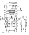
- FIG. 1 is a block diagram illustrating a configuration of the radar apparatus according to the first embodiment.
- the radar apparatus according to the first embodiment includes, as illustrated in FIG. 1 , an array antenna 11, low-noise amplifiers (hereinafter, referred to as "LNAs”) 12, power amplifiers (hereinafter, referred to as "HPAs”) 13, mixers (MIX illustrated in FIG. 1 ) 14, analog-digital (hereinafter, referred to as "A/D”) converters 15 (which may be configured to mount a memory that temporarily stores digital data therein), branching units (hereinafter, referred to as "HYBs”) 16, envelope detector units (HIL illustrated in FIG. 1 ) 17, a cross-correlation calculator (XCORR illustrated in FIG.
- LNAs low-noise amplifiers
- HPAs power amplifiers
- MIX illustrated in FIG. 1 mixers
- A/D analog-digital converters 15
- HYBs branching units
- HIL envelope detector units
- XCORR cross-
- a data clipper 19 18, a data clipper 19, a phase compensator 20, a signal processing unit 21, an oscillation module 22, a central processing unit (CPU) 23, a switch controller 24, switches 25, and a transmission cycle setting unit (P/Q illustrated in FIG. 1 ) 26.
- Those respective units are realized by components of software, components of hardware, or a combination thereof (refer to the [Others] section).
- the oscillation module 22 may be so configured as to digitally directly generate an FMCW signal, such as a direct digital synthesizer (DDS).
- DDS direct digital synthesizer
- the oscillation module 22 has a general analog circuit configuration, that is, a combination of a baseband oscillator (BB-OSC illustrated in FIG. 1 ) and a radio-frequency voltage-controlled oscillator (RF-VCO illustrated in FIG. 1 , which may also be a current-controlled oscillator).
- BB-OSC baseband oscillator
- RF-VCO radio-frequency voltage-controlled oscillator
- a reference signal output from the baseband oscillator is transmitted to the radio-frequency voltage-controlled oscillator, and a system reference signal modulated in frequency by using the reference signal is output from the radio-frequency voltage-controlled oscillator.
- a triangular wave is used as the reference signal.
- Each HPA 13 is disposed in a processing system corresponding to each transmitting antenna.
- two HPAs 13 HPA13 (#1) and HPA 13 (#2) are disposed.
- the HPAs 13 amplify the system reference signal output from the oscillation module 22, and output the amplified signal from the antenna selected as the transmitting antenna as a target detection probe signal.
- the array antenna 11 has N antenna (sensor) elements which are arranged at respective different spatial positions.
- the array antenna 11 forms a uniform linear array antenna (ULA antenna) in which the respective antenna elements are linearly arranged at regular intervals.
- UAA antenna uniform linear array antenna
- two antenna elements located on both ends of the respective antenna elements that are linearly arranged are shared both for transmission and reception, and the other antenna elements are used only for the reception.
- the antenna element shared both for transmission and reception is represented as a shared antenna A R1/T1 or a shared antenna A RN/T2 .
- the shared antennas are configured to switch between transmission and reception in time division by the switch 25.
- the antenna elements that operate as receiving antennas are represented by A R1 to A RN
- the antenna elements that operate as the transmitting antennas are represented by A T1 and A T2 .
- an aperture enlarging technique is employed in which a plurality of transmitting antennas and a plurality of receiving antennas operate in a coordinated manner to increase the number of effective receiving antennas.
- the switch 25 switches the shared antenna to the transmitting antenna or the receiving antenna according to a control signal from the switch controller 24. More specifically, the switch 25 (#1) selectively connects the shared antenna A R1/T1 to the HPA 13(#1) or the LNA 12(#1). With connection to the HPA 13(#1), the shared antenna A R1/T1 operates as the transmitting antenna A T1 , and with connection to the LNA 12(#1), the shared antenna A R1/T1 operates as the receiving antenna A R1 . Likewise, the switch 25 (#2) selectively connects the shared antenna A RN/T2 to the HPA 13 (#2) or the LNA 12(#N). With connection to the HPA 13(#2), the shared antenna A RN/T2 operates as the transmitting antenna A T2 , and with connection to the LNA 12 (#N), the shared antenna A RN/T2 operates as the receiving antenna A RN .
- the switch controller 24 controls a switching timing of the switch 25 according to transmission cycle information transmitted from the CPU 23 and a cycle T f of the reference signal output from the baseband oscillator of the oscillation module 22.
- the transmission cycle setting unit 26 transmits an instruction for changing the cycle T f of the reference signal or the transmission cycle information (P/Q) to the CPU 23 according to a request from the signal processing unit 21.
- the transmission cycle information (P/Q) indicates a ratio (P) of time slots using the transmitting antenna A T1 and a ratio (Q) of time slots using the transmitting antenna A T2 , with the cycle T f of the reference signal as one unit (duty ratio when the respective shared antennas are switched for purpose of transmission or reception in one time slot is ignored).
- the transmitting antenna A T1 radiates probe signals in a given cycle, and the receiving antenna A RN continuously receives an echo signal.
- the transmitting antenna A T2 radiates the probe signals in a given cycle, and the receiving antenna A R1 continuously receives the echo signal.
- Each LNA 12 is disposed in a processing system corresponding to each receiving antenna.
- an LNA 12(#2) to an LNA 12 (#N-1) are always connected to the receiving antennas A R2 to A RN-1 , respectively.
- the LNA 12 (#1) is connected to the receiving antenna A R1 by switching the switch 25(#1).
- the LNA 12(#N) is connected to the receiving antenna A RN by switching the switch 25(#2).
- the LNA 12 receives a reception signal from the connected receiving antenna, and amplifies the reception signal.
- the amplified signal is transmitted to the mixers 14.
- Each mixer 14 is connected to the LNA 12.
- the mixer 14 mixes the signal amplified by each LNA 12 with the system reference signal transmitted from the oscillation module 22 to convert a radio-frequency echo signal into a baseband signal.
- Each A/D converter 15 converts the baseband signal output from the mixer 14 into a digital baseband signal at a given sampling frequency.
- the digital baseband signal is simply referred to as "demodulated signal”.
- the HYBs 16 are disposed in the respective processing systems corresponding to the receiving antennas A R1 and A RN in order to process the demodulated signals of the signals received by the receiving antennas A R1 and A RN . More specifically, the HYB 16(#1) is connected to the A/D converter 15(#1), and the HYB 16(#2) is connected to the A/D converter 15(#N).
- each HYB 16 is disposed in a processing system that processes a signal received by a receiving antenna of a combination of a transmitting antenna and the receiving antenna whose spatial phases become equal to each other in the array antenna 11 (accordingly, there is no need to limit a portion where the HYB and the HIL are mounted to the receiving antennas on the outermost edges of the array antenna).
- the aperture synthesizing operation is executed on the basis of the signal received by the combination of the transmitting antenna and the receiving antenna which gives the equal spatial phase as described above.
- the combination of the transmitting antenna and the receiving antenna employed based on the aperture synthesis as described above is referred to as “reference combination”, and the transmitting antenna and the receiving antenna in the reference combination are referred to as “reference transmitting antenna” and “reference receiving antenna”, respectively.
- the combination of the reference transmitting antenna A T1 and the reference receiving antenna A RN , and the combination of the reference transmitting antenna A T2 and the reference receiving antenna A R1 are the reference combinations (as other specific reference combinations, a combination of the reference transmitting antenna A T1 and the reference receiving antenna A R1 , and a combination of the reference transmitting antenna A T2 and the reference receiving antenna A RN are conceivable. In this case, a reference phase length is zero).
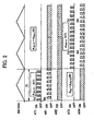
- FIG. 3 is a conceptual diagram illustrating conditions for satisfying the aperture synthesis in an example in which the device operates according to the timing chart of FIG. 2 .
- FIG. 3 illustrates an appearance in which a probe signal is radiated from the reference transmitting antenna A T1 and an echo signal thereof is received by the reference receiving antenna A RN in the time slot [0, T f ] (hereinafter, also referred to as "measurement time period A"). Further, FIG. 3 also illustrates an appearance in which the probe signal is radiated from the reference transmitting antenna A T2 and an echo signal thereof is received by the reference receiving antenna A R1 in the time slot [T f , 3T f ] (hereinafter, also referred to as "measurement time period B").
- the aperture synthesis is established for the respective signals received in the respective measurement time periods A and B when the phase length of the signal received by the reference receiving antenna A RN in the measurement time period A matches the phase length of the signal received by the reference receiving antenna A R1 in the measurement time period B.
- Each HYB 16 branches the demodulated signal output from the A/D converter 15 in a direction of the envelope detector unit 17 and in a direction of the data clipper 19.
- the envelope detector units 17 are connected to the respective HYBs 16 in order to process the demodulated signals of the signals received by the reference receiving antennas.
- the envelope detector units 17 detect envelope components of the signals branched by the HYBs 16.
- the envelope components acquired by the envelope detector units 17 may be referred to as "envelope signals".
- the envelope detector units 17 detect, for example, the existence of a signal component having a cycle longer (a frequency lower) than the minimum frequency resolution of Fourier transformation (such as fast Fourier transformation (FFT)) conducted by the signal processing unit 21, the envelope detector units 17 transmit the acquired envelope signal to the cross-correlation calculator 18.
- FFT fast Fourier transformation
- the envelope detector units 17 may ask the transmission cycle setting unit 26 to request the probe signal radiation in accordance with the above-mentioned transmit cycle information (P and Q) to the CPU 23 (including a change in the values of P, Q, and T f ).
- the envelope detector units 17 are realized by using, for example, a diode detector, a quadrature demodulator, a Hilbert transformer, a wavelet transformer, or a filter bank.
- FIG. 4 is a diagram illustrating an input signal to the envelope detector unit and an envelope signal output from the envelope detector unit.
- FIG. 4 illustrates a case using the timing chart of FIG. 2 , in which two targets to be detected are set, various factors (distance, angle, and velocity) of the respective targets to be detected are set to T 1 (40 meters (m), 0 degrees (deg), and 10 kilometers per hour (km/h) and T 2 (40 (m), 3 (deg), and 12.5 (km/h), and a signal-to-noise ratio (SNR) is set to 30 decibel (dB).
- graphs (A-I) and (B-I) illustrated at an upper stage represent the signals input to the envelope detector units 17, and graphs (A-O) and (B-O) illustrated at a lower stage represent the signals output from the envelope detector units 17.
- the graphs (A-I) and (A-O) illustrate the demodulated signal obtained during [0, T f ] in the example of FIG. 2 , and the results of signal processing to which the demodulated signal is subjected.
- the graphs (B-I) and (B-O) illustrate the demodulated signal obtained during [T f , 3T f ] in the example of FIG. 1 , and the results of signal processing to which the demodulated signal is subjected.
- the cross-correlation calculator 18 takes a cross correlation between the envelope signal related to the signal received by the reference receiving antenna A RN corresponding to the reference transmitting antenna A T1 , and the envelope signal related to the signal received by the reference receiving antenna A R1 corresponding to the reference transmitting antenna A T2 .
- the cross-correlation calculator 18 retains the envelope signal processed in the measurement time period [0, T f ]in a memory (not shown), and detects, as a time lag, a timing at which a phase of the envelope signal processed in a subsequent measurement time period [T f , 3T f ] matches a phase of the previous envelope signal.
- the cross-correlation calculator 18 subjects a no-signal interval of the envelope signal acquired in the measurement time period [0, T f ], which is short in signal length, to zero padding, in order to conform the lengths of both the envelope signals to each other.
- the time lengths occupied by the respective envelope signals are values determined by the transmit cycle information (P/Q illustrated in FIG. 1 ) transmitted from the CPU.
- a "time" in the graph having a time axis represents not the measurement time period per se, but an index as data. Accordingly, a count starts from zero irrelevant to a difference from a real measurement time period.
- FIG. 5 is a graph illustrating a cross-correlation value between the respective envelope signals illustrated in FIG. 4 .
- the cross-correlation calculator 18 determines the time lag as 240. This is also illustrated in FIG. 4 . Specifically, a phase of a waveform after the time index 240 in the graph (B-O) of FIG. 4 matches a phase of a waveform of a (valid) signal portion in the graph (A-O) of FIG. 4 .
- the cross-correlation calculator 18 When detecting the time lag between the envelope components of the demodulated signals of the reference combination as described above, the cross-correlation calculator 18 transmits the time lag to the data clipper 19. When a clear peak is not obtained in the cross correlation, that is, when a peak value of the cross correlation is lower than a given threshold value, or when several peaks having the almost same amplitude appear, the cross-correlation calculator 18 may request the transmission cycle setting unit 26 to instruct a change in the cycle T f of the reference signal or the transmit cycle information (P/Q).
- the data clipper 19 receives the demodulated signals of the signals received by the respective receiving antennas in the respective time slots from the respective A/D converters 15, and retains the respective demodulated signals in a memory (that is, the memory may save the output from the A/D converter 15 obtained in the above-mentioned "one cycle of the operation as a device" in an accessible manner for each time slot and each receiving system (antennas to A/D converters). Further, in the respective operations which are described later, data from a desired receiving system in a desired time slot may be appropriately output).
- the data clipper 19 conforms the phases of the envelope components of the respective input demodulated signals to each other based on the time lag transmitted from the cross-correlation calculator 18.
- the data clipper 19 clips signals for a T f time after the time lag from the respective demodulated signals during [T f , 3T f ].
- the data clipper 19 may acquire data that matches the respective demodulated signals during [0, T f ] in phase of the envelopes, from the respective demodulated signals during [T f , 3T f ] (that is, a data string in which the phases of the envelopes are conformed to each other from data strings acquired in different time slots).
- the data clipper 19 transmits the respective demodulated signals thus compensated in phase to the phase compensator 20.
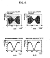
- FIG. 6 is graphs illustrating the results of phase compensation of the envelope components.
- the envelopes of the respective signals (derived from the reference receiving antenna) clipped by the data clipper 19 ((B-O) of FIG. 6 ) match the envelopes of the demodulated signals during [0, T f ] ((A-O) of FIG. 6 ) in phase.
- the phase compensator 20 receives the respective demodulated signals in which the phases of the envelope components match each other, which are transmitted from the data clipper 19 (in a specific example used herein, a length of data transmitted from the data clipper is the same as that of the time slot [0, T f ]), and compensates a residual phase error of the respective demodulated signals.
- the phase compensator 20 calculates an amount of compensation (in a time domain) by using Expression (2.4) that is described later, and, according to the amount of compensation, compensates the phase errors of the respective demodulated signals in the measurement time period [T f , 3T f ], which are clipped so that the phases of the envelopes match each other by the data clipper, so as to conform to the phase errors of the respective demodulated signals in another measurement time period [0, T f ] (in a case of data where the phases of the envelopes match each other, data of the time domain may be converted into data of the frequency domain by FFT, and the amount of compensation may be calculated through Expression (1.13) so that the above-mentioned compensating process is implemented in the frequency domain).
- the respective signals thus compensated in the residual phase errors are transmitted to the signal processing unit 21.
- the signal processing unit 21 subjects the respective signals transmitted from the phase compensator 20 to aperture synthesis, and applies, to the signals that have been subjected to aperture synthesis, a known angle estimation algorithm (hereinafter, referred to simply as "angle measurement algorithm") such as a digital beam forming (DBF) method, a multiple signal classification (MUSIC) method, or a propagator method based on an improved spatial-smoothing matrix (PRISM) method.
- a known angle estimation algorithm such as a digital beam forming (DBF) method, a multiple signal classification (MUSIC) method, or a propagator method based on an improved spatial-smoothing matrix (PRISM) method.
- the signals that have been subjected to aperture synthesis in the time domain may be converted into signals of the frequency domain by Fourier transformation (such as fast Fourier transformation (FFT)), and the angle measurement algorithm may be applied to the signals of the frequency domains.
- the aperture synthesizing method and the angle measurement algorithm may be conducted by using a known technique, and therefore their description is
- the signal processing unit 21 may acquire, from the envelope detector units 17, information on frequencies of the envelopes per se or information on the respective frequencies of the signal components that configure the envelopes, and acquire the envelope components (or above-mentioned respective amounts) through a given method.
- the signal processing unit 21 may give an instruction to change the cycle T f of the reference signal from the transmission cycle setting unit 26 when the frequency component (or above-mentioned respective amounts) is smaller than a given threshold value.
- FIG. 7 is a block diagram illustrating the configuration of the radar apparatus different from that of the first embodiment.
- FIG. 8 illustrates the timing chart used in the radar apparatus of FIG. 7 .
- the examination using the following mathematical expressions is newly disclosed herein. Further, a cycle of the reference signal is referred to as "T f " as in the above-mentioned first embodiment.
- the shared antenna A R1/T1 is used as the transmitting antenna or the receiving antenna, and the receiving antennas A R2 to A RN-1 and the shared antenna A RN/T2 are used as the receiving antennas.
- the shared antenna A RN/T2 is used as the transmitting antenna or the receiving antenna, and the receiving antennas A R2 to A RN-1 and the shared antenna A R1/T1 are used as the receiving antennas.
- the respective probe signals are represented by the respective following Expressions (1.1a) and (1.1b).
- ⁇ c represents a carrier angular frequency of the RF-VCO that configures the oscillation module 22.
- ⁇ of v TX2 (t) represents a phase shift due to a transmission time lag. In the following description, the angular frequency and the frequency are not distinguished from each other.
- h(t) is defined by the above-mentioned Expression (1.2) with respect to a reference signal f(x) from the BB-OSC that configures the oscillation module 22.
- f(x) is expressed by the following Expression (1.3).
- ⁇ is a one-sided modulation bandwidth.
- f x ⁇ 4 ⁇ ⁇ ⁇ ⁇ T f ⁇ x + ⁇ ⁇ ⁇ : - T f 2 ⁇ x ⁇ 0 - 4 ⁇ ⁇ ⁇ ⁇ T f ⁇ x + ⁇ ⁇ ⁇ : 0 ⁇ x ⁇ T f 2
- the reception signals v TX1 RX,n (t) represent the respective signals resulting from receiving the echo signals of the probe signals radiated from the transmitting antenna A T1 by the receiving antennas A R1 to A RN in the measurement time period [0, T f ].
- the reception signals v TX2 RX,n (t) represent the respective signals resulting from receiving the echo signals of the probe signals radiated from the transmitting antenna A T2 by the receiving antennas A R1 to A RN in the measurement time period [T f , 2T f ].
- n TX1 n (t) and n TX2 n (t) are additive Gaussian noise.
- the respective reception signals are mixed with the system reference signals output signals of the oscillation module 22) by the mixers 14 so as to be converted into baseband signals.
- the signal processing unit 21 subjects those digital baseband signals (hereinafter, referred to as "demodulated signals”) to the following signal processing to estimate the angles, distances and velocities of the targets to be detected.
- Expression (1.8) -4 ⁇ m 0 /T f , which is a frequency component due to the distance delay (sign is different in the up-chirp of FM) is replaced with ⁇ B m , and a constant term ⁇ c ⁇ m 0 + ⁇ m 0 is included in ⁇ TX1 (t) and ⁇ TX2 (t).
- Expression (1.7a) and Expression (1.7b) may be rewritten into the following Expressions (1.9a) and (1.9b).
- a condition under which the aperture synthesis is established for the respective demodulated signals v TX1 RX,n (t) and v TX2 Rx,n (t) acquired in the two measurement time slots [0, T f ] and [T f , 2T f ] is that the phase lengths of the respective demodulated signals v TX1 RX,n (t) and v TX2 RX,1 (t) in the reference combination match each other in both the measurement time periods.
- treatment of the phase errors ⁇ TX1 (t) and ⁇ TX2 (t) expressed in the above-mentioned Expressions (1.9a) and (1.9b) becomes critical issue.
- the aperture synthesizing operation is conducted in the signal processing unit 21.
- the signals obtained at the respective measurement time periods are subjected to Fourier transformation so as to be transformed into data of the frequency domain. This is described in detail below with an example of the demodulated signal v TX1 RX,n (t).
- the Fourier transformation result of the signal component corresponding to an m-th target may be represented by Expression (1.11a) except for the spatial phase.
- a left side of Expression (1.11a) is obtained by Expression (1.11c), for example, in the case where definition is made as in the following Expression (1.11b).
- the frequency domain signals converted from signals of the time domains expressed in the above-mentioned Expressions (1.9a) and (1.9b) may be represented by the following Expressions (1.12a) and (1.12b).
- the signal processing unit 21 acquires a phase error d ⁇ (k) in the respective frequency indexes k by using the respective demodulated signals corresponding to the reference combinations through the following Expression (1.13) (in this example, attention should be paid to a fact that the spatial phases are equal to each other for the reference combination) .
- the signal processing unit 21 multiplies the amount of compensation exp[-jd ⁇ (k)] based on the phase error d ⁇ (k) by V TX2 RX,n (k) with respect to all of n and k, thereby conforming the phase error of V TX2 RX,n (k) to the phase error ⁇ TX1 (t) of V TX1 RX,n (k), as a result of which the aperture synthesis is established. That is, the synthetic aperture signal obtained by the signal processing unit 21 in the radar apparatus of FIG. 7 is represented by the following Expressions (1.14a) and (1.14b) (for simplification, influence of an additive noise component is omitted). [Ex.
- the signals of the reference receiving antennas after having being subjected to the aperture synthesis are defined by the following Expression (1.15) based on a fact that the spatial phases of the respective signals of the reference receiving antennas are equal to each other.
- a vector V (k) having, as elements, the signals of the reference receiving antennas previously defined and the signals received by the other respective receiving antennas, a noise signal vector N(k), an angular matrix A, and a target signal vector X(k), are defined by the following Expressions (1.16a), (1.16b), (1.16c), and (1.16d), respectively, to thereby derive, for the aperture synthesized signal, a basic relational expression of array signal processing such as Expression (1.17) (needless to say, the respective expressions are notations related to the signal elements in which the frequency index is k). [Ex.
- the signal processing unit 21 processes the signal vector defined by Expression (1.17) with the use of a known angle measurement algorithm such as DBF, MUSIC, or PRISM.
- FIG. 9 is a diagram illustrating a scene setting example.
- the problem on the radar apparatus illustrated in FIG. 7 is examined through mathematical expressions by using scene setting illustrated in FIG. 9 .
- the number of antenna elements N is 4, an interval d between the antenna elements is 1.8 ⁇ ( ⁇ is a wavelength of the carrier signal), and the number of sampling K is 512.
- T 9 are T 1 : (40 (m), 0 (deg), and 10 (km/h)) and T 2 : (40(m), 3(deg), and 11(km/h)), and SNR is 30 (dB) .
- the various target factors may be slightly changed for each of the calculation examples.
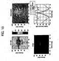
- the aperture synthesizing operation is conducted according to the above-mentioned procedure, and an angle is measured by the frequency domain, to thereby obtain the results illustrated in FIG. 10 .
- FIG. 10 is graphs illustrating the angle measurement results in the radar apparatus illustrated in FIG. 7 different from that in the first embodiment.
- the distances to the targets to be detected may be estimated substantially precisely, the respective targets to be detected which exist at 0 degrees and 3 degrees are erroneously estimated as one target to be detected which exists in the vicinity of about 1.5 degrees.
- FIG. 11 is graphs illustrating the angle measurement results for the signal of the time domain, which has been transformed from the signal of the frequency domain used in FIG. 10 .
- a target angle which should be temporally fixed in the drawing, referred to as "gradient of spatial phase ⁇ m n (t) ") changes according to a time.
- a relative velocity difference between two targets to be detected is 1 (km/h) ( ⁇ 0.28 (m/sec)
- the frequencies ⁇ B 1 and ⁇ B 2 determined by the distance delay have the same value (Refer to Expression (2.1). More specifically, the frequencies ⁇ B 1 and ⁇ B 2 are about 13 (kHz) at 40 (m)).
- a phase corresponding to the Doppler frequency and the spatial phase are considered, for example, a term in brackets of exp of a summation part of v TX1 RX,n (t) in the above-mentioned Expression (2.2a) may be represented by the above-mentioned Expression (2.3a).
- a spatial phase (2 ⁇ / ⁇ ) (n-1) dsin ( ⁇ m ) which is temporally fixed is influenced by a Doppler phase shift (2 ⁇ / ⁇ )2v m t that varies with time, and exhibits temporally complicated behavior by combination of the velocities, times, and angles of the respective targets (Doppler frequency is about 1.
- FIG. 12 is graphs illustrating the results of applying the angle measurement algorithm to the signal thus obtained. Referring to FIG. 12 , the phase difference of the signal is cancelled in the time domain, to thereby cancel a change in angle with time as expected. However, the number and angles of targets to be detected remain erroneously estimated.
- the rightmost side of the Expression (2.5) means that, as a result of synthesizing the signals from two targets, the synthesized signal substantially acts as one signal that may be represented by a product of a complex component exp() and a real number component cos(). That is, the complex component may be interpreted as a signal from one target to be detected having an average Doppler frequency and an average angle of the two targets to be detected. Further, the real number component may be interpreted as a beat signal between Doppler signals of the two targets to be detected. Consequently, a signal resulting from subjecting a complex signal derived from the above-mentioned pseudo single target to the amplitude modulation (AM) by the above-mentioned beat signal is a substance of the above-mentioned Expression.
- AM amplitude modulation
- FIG. 13 is graphs illustrating together the demodulated signal in the reference receiving antenna and the envelope signal (AM component) obtained by subjecting the demodulated signal to the envelope detection, in order to examine the validity of the above-mentioned conclusions.
- the respective demodulated signals (Expression (2.2a) and (2.2b)) are illustrated on the upper portion, and the respective envelope signals are illustrated on the lower portion.
- FIG. 13 illustrate that the phases of the reception signals obtained in the two measurement time periods [0, T f ] and [T f , 2T f] are largely different depending on an influence of the envelope. Further, the frequencies of the respective envelope signals (when being regarded as a bipolar signal) are about 73 (Hz), and far smaller than 500 (Hz) which is the minimum frequency resolution of the device. Therefore, it is apparent that the aperture may not be synthesized with precision even if the phase compensation is conducted in the frequency domain.
- the envelope components of the demodulated signals of the signals received by the respective reference receiving antennas are detected (envelope detector unit 17).
- the cross correlation of the respective envelope components are taken to acquire a time lag in which the phases of the respective envelope components match each other (cross-correlation calculator 18).
- the cross-correlation processing by the cross-correlation calculator 18 is represented in the following Expression (3.1). Based on the acquired amount of delay, a signal portion in which the phases of the envelope components match each other is acquired from the respective reception signals (data clipper 19).
- a residual phase error is compensated by the phase compensator 20 (Because a compensation of the residual phase may be implemented in the frequency domain for data in which the phases of the envelopes match each other, an output signal from the data clipper may be converted into a signal of the frequency domain in the signal processing unit 21 to compensate the residual phase.), and the aperture synthesizing operation and the angle measurement algorithm are applied (signal processing unit 21). [Ex.
- the signal portion in which the phases match each other may be acquired so that the aperture synthesis is established in the respective measurement time periods ([0, T f ] and [T f , 3T f ]).
- the radar apparatus in which the number of effective receiving antennas is increased under an arbitrary condition, and a small number of actual antennas (sensors) are provided may be realized. That is, the angle estimation with high precision may be realized for the targets, the number of which is larger than the separable with number of the actual receive sensors.
- FIG. 14 is graphs illustrating the results of applying the angle measurement algorithm in the time domain in the radar apparatus according to the first embodiment. For example, when PRISM is used as the angle measurement algorithm, the angles (0 degrees and 3 degrees) of the respective targets to be detected in the scene setting of FIG. 9 are precisely estimated.
- FIG. 15 is graphs illustrating the results of applying the angle measurement algorithm in the frequency domain in the radar apparatus according to the first embodiment.
- the signal processing unit 21 transforms the aperture synthesized signal into the signals in the frequency domain by Fourier transformation, and applies the angle measurement algorithm to the transformed frequency domain signal.
- the distances and angles of the respective targets to be detected in the scene setting of FIG. 9 are precisely estimated.
- the phase compensation may thereafter be implemented by the frequency domain.
- the radar apparatus 1 of the first embodiment even when a plurality of targets to be detected exist at the same distance and the respective targets to be detected move with a small velocity difference, the angles and distances (and also velocities) of the targets to be detected may be estimated with precision.
- FIG. 16 is a block diagram illustrating a configuration of the radar apparatus 1 according to the second embodiment.
- the radar apparatus 1 according to the second embodiment has the HYB 16 and the envelope detector unit 17 only in a processing system corresponding to the receiving antenna A RN in one (combination of the transmitting antenna A T1 and the receiving antenna A RN ) of the reference combinations.
- the radar apparatus 1 according to the second embodiment has an envelope frequency estimator 31 (hereinafter, referred to as "EF estimator”) 31 instead of the data clipper 19 of the first embodiment.
- EF estimator envelope frequency estimator
- the radar apparatus 1 according to the second embodiment newly has a delay element 32 in a processing system corresponding to the transmitting antenna A T2 .
- the other processing units are the same as those in the first embodiment.
- the EF estimator 31 estimates a frequency of the envelope signal (Because the envelope is normally composed of signal components having several frequencies, a frequency of the envelope synthesizing those signal components).
- the frequency to be estimated is calculated, for example, by using Expression (3.3) that is described later.
- the EF estimator 31 calculates the time lag according to the estimated frequency information.
- the time lag is calculated, for example, by using Expression (3.4) that is described later.
- the EF estimator 31 may acquire information on the frequencies of the respective signal components that configure the envelopes. In this case, the EF estimator 31 may give an instruction to change the cycle T f of the reference signal from the transmission cycle setting unit 26 when the frequencies are smaller than a given threshold value.
- the delay element 32 delays the system reference signal transmitted from the oscillation module 22 by the time lag calculated by the EF estimator 31. As a result, a radiation time of the probe signal from the transmitting antenna A T2 is delayed by the time lag.
- the transmission may be stopped for a period of time corresponding to the time lag by a switch mechanism instead of the delay element 32 (For example, a control signal to the switch 25 (#2) may be transmitted to the switch controller 24 through a CPU.).
- v 1 and v 2 represent the velocities of the targets to be detected T 1 and T 2 , respectively.
- the radiation time of the probe signal from another transmitting antenna A T2 is delayed by ⁇ T based on the time lag calculated from the frequency information of the envelope of the echo signal received by the reference receiving antenna A RN in correspondence with the probe signal radiated from the transmitting antenna A T1 .
- the phases of data in which the aperture synthesis is established in the respective measurement time periods [0, T f ] and ⁇ T+ [0, T f ]) may be conformed to each other (A restriction when this embodiment is applied in the device disclosed in FIG. 16 is ⁇ T ⁇ T f .
- the present invention is not limited thereto.
- FIG. 17 is graphs illustrating the results of phase compensation of the envelope components according to the second embodiment.
- a scene is used in which various factors (distance, angle, and velocity) of the targets to be detected are set to T 1 (40 m, 0 deg, and 10 km/h) and T 2 (40 m, 3 deg, and 12.0 km/h), and SNR is set to 30 (dB).
- T 1 40 m, 0 deg, and 10 km/h
- T 2 40 m, 3 deg, and 12.0 km/h
- SNR is set to 30 (dB).
- FIG. 18 is graphs illustrating the results of applying the angle measurement algorithm in the frequency domain in the radar apparatus according to the second embodiment.
- the signal processing unit 21 transforms the aperture synthesized signal into the signals in the frequency domain by Fourier transformation, and applies the angle measurement algorithm to the transformed frequency domain signal (Alternatively, because the phase compensation of the envelopes of the respective reception signals has already been performed through radiating operation of probe signal from the respective transmitting antennas, for example, the reception signals obtained in the respective measurement time periods in the phase compensator 20 may be subjected to Fourier transformation, and the signals transformed in the frequency domain may be subjected to the residual phase compensation to the aperture synthesis, and in the signal processing unit 21, only processing such as the angle measurement algorithm may be conducted.). In this case, the distances and angles of the respective targets to be detected in the above-mentioned scene setting are also estimated with precision.
- the number of effective antennas after aperture synthesis has been conducted is 2xN-1.
- the number of coherent signals detectable by an array configured by the receiving antennas of this number is G[2 ⁇ (2 ⁇ N-1)/3] using the Gauss symbol G[].
- the EF estimator 31 estimates the frequency of the signal components, that configure the envelope obtained by the envelope detector units 17, as value making Expression (3.5) minimum.
- HIL[v TX1 RX,N (t)] in Expression (3.5) means that the echo signal received by the reference receiving antenna A RN corresponding to the probe signal radiated from the transmitting antenna A T1 is subjected to the envelope detection.
- the radar apparatus 1 may operate as follows.
- the radar apparatus 1 radiates the probe signals from at least any one transmitting antenna A Tm of the M transmitting antennas for only a regular period of time QT f , subjects the echo signal obtained from the reference receiving antenna A Rn corresponding to A Tm to the envelope detection, and estimates the frequency ⁇ env , of the envelope.
- FIG. 19 is a diagram illustrating a modified example of the radar apparatus according to the first embodiment.
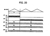
- the radar apparatus 1 according to the modified example includes the array antenna 11 having the receiving antennas A R1 to A RN used only for reception and the transmitting antennas A T1 to A T2 used only for transmission.
- intervals between the respective receiving antennas are set to d
- intervals between the respective transmitting antennas are set to (N-1)xd.
- FIG. 19 illustrates the modified example of the first embodiment. However, this configuration may be applied to the second embodiment.
- FIG. 20 is a timing chart in the modified example.
- the antenna (sensor) intervals are not limited to regular intervals.
- the configuration of the radar apparatus 1 according to the first and second embodiments may be switched to the configuration illustrated in FIG. 7 (For example, in the device according to the first embodiment, this may be determined because peaks having substantially the same amplitude are obtained at the some different values of delay from the cross-correlation calculator 18.
- the minimum time lag is applied as a necessary time lag among the plurality of peaks, there is no need to incorporate a configuration in which the signal is purposely switched to the frequency domain to conduct phase compensation therein.).
- a linear approximation equation may be obtained by least squares method, and then the phase focusing of the envelope components may be conducted as the linear trend (In this case, because the demodulated signal is an original constant envelope of an FMCW radar, it goes without saying that the same operation as that of the above-mentioned notation may be conducted.).
- an operation mode may be switched. That is, for example, the sampling frequency is changed, irregular interval sampling is conducted, a value is used which is estimated by means such as a Kalman filter from values of various target factors obtained at a time point when the target to be detected has been normally detected, a measurement time period is shifted by a given time, or an angle is measured without conducting the aperture synthesis.
- the frequency ⁇ B determined according to the distance delay takes a relatively large value as described above. Therefore, if the frequency ⁇ B is detected by a filter bank or the like in advance and v TX1/2 RX,n (t) is multiplied by exp(-j ⁇ B t) to demodulate the component of the following Expression (4.1), Expression (4.1) may be rewritten in an expression of the same form as Expression (1.17). In other words, the demodulated signal is treated as if the echo signal is configured by only the Doppler component, thereby enabling an angle estimating process.
- v TX1/2 RX,n (t) being multiplied by exp(-j ⁇ B t)
- all of v TX1/2 RX,n (t) may be subjected to the envelope detection.
- the signal obtained by subjecting the respective signals to the envelope detection is
- the signal obtained by subjecting the respective signals to the envelope detection is close to demodulated signal of 100% amplitude-modulated signal. Therefore, angle estimation is conducted on an aircraft value of the signal, or the aperture synthesis is realized by time diversity.
- the baseband signal branched to at I/Q channel is obtained by a quadrature demodulator, there is no need to additionally provide an envelope detector unit, and the respective envelope components may be detected by taking the square root of a sum of the square of an I channel and the square of a Q channel.
- reception signals from all of the receiving antennas including the receiving antennas that configure the reference combinations may be subjected to the envelope detection, and the angle measurement algorithm may be applied to the envelope signals per se of the respective receiving antennas obtained after the aperture synthesis has been conducted (As described above, this is substantially equivalent to a manner of dealing the demodulated signal as if the echo signal is configured by only the Doppler component. Therefore, in order to prevent sign of the angle measurement results from being inverted, it is desirable to transform the monopolarized envelope signal into a bipolar signal referring to the magnitude of the minimum phase shift.).
- the following processing may be conducted. That is, the reception signals are branched for each of the receiving antennas in which one of the branched reception signals passes through a first low-pass filter (LPF) that cuts off frequencies equal to or higher than the velocity resolution, and the other of the branched reception signals passes through a second LPF or a band pass filter (BPF) which allows frequencies equal to or higher than a cutoff frequency of the first LPF to pass therethrough.
- LPF low-pass filter
- BPF band pass filter
- a component of hardware is a hardware circuit which is, for example, a field programmable gate array (FPGA), an application-specific integrated circuit (ASIC), a gate array, a combination of logic gates, a signal processor circuit, and an analog circuit.
- FPGA field programmable gate array
- ASIC application-specific integrated circuit
- a component of hardware is a hardware circuit which is, for example, a field programmable gate array (FPGA), an application-specific integrated circuit (ASIC), a gate array, a combination of logic gates, a signal processor circuit, and an analog circuit.
- FPGA field programmable gate array
- ASIC application-specific integrated circuit
- a component of software is a part (segment) that realizes the above-mentioned processing as software, but is not a concept that limits a language that realizes the software and a development environment.
- the component of software is, for example, a task, a process, a sled, a driver, firmware, a database, a table, a function, a procedure, a sub-routine, a given portion of a program code, a data structure, an array, a variable, and a parameter.
- Those components of software are realized, in a computer, on one or a plurality of memories, or realized by execution of data on one or a plurality of memories through one or a plurality of processors (for example, central processing unit (CPU) and digital signal processor (DSP)).
- processors for example, central processing unit (CPU) and digital signal processor (DSP)
- the above-mentioned respective embodiments do not limit a manner of realizing the above-mentioned respective processing units.
- the respective processing units may be configured by a manner realizable by a normally skilled person in this technical field as the above-mentioned component of hardware, the above-mentioned component of software, or a combination thereof.
Landscapes
- Engineering & Computer Science (AREA)
- Radar, Positioning & Navigation (AREA)
- Remote Sensing (AREA)
- Computer Networks & Wireless Communication (AREA)
- Physics & Mathematics (AREA)
- General Physics & Mathematics (AREA)
- Radar Systems Or Details Thereof (AREA)
Claims (7)
- Dispositif de radar (1) configuré de manière à détecter une cible par synthèse d'ouverture de signaux obtenus à partir d'antennes réceptrices (AR1, ..., ARN) dans une antenne réseau (11) présentant une pluralité d'éléments d'antenne, dont chacun est utilisé en qualité d'au moins l'une parmi des antennes émettrices (AT1, AT2) et des antennes réceptrices (AR1, ..., ARN), caractérisé en ce qu'il comprend :une unité de détection d'enveloppe (17) configurée de manière à acquérir une composante d'enveloppe d'un signal obtenu à partir d'une antenne réceptrice (AR1, ..., ARN) dans au moins une combinaison d'une pluralité de combinaisons d'antennes émettrices (AT1, AT2) et d'antennes réceptrices (AR1, ..., ARN) dont les phases spatiales du signal sont mutuellement égales dans l'antenne réseau (11) ;une unité de détermination (18, 31) configurée de manière à déterminer un décalage temporel de la composante d'enveloppe acquise par l'unité de détection d'enveloppe (17) en tant qu'une quantité de compensation dans ladite au moins une combinaison ; etune unité de compensation (20) configurée de manière à compenser une phase du signal obtenu à partir de chacune des antennes réceptrices (AR1, ..., ARN) avant la synthèse, en utilisant la quantité de compensation déterminée par l'unité de détermination (18), ou à compenser une phase d'un signal rayonné par l'antenne émettrice (AT1, AT2) dans une autre combinaison, différente de ladite au moins une combinaison.
- Dispositif de radar (1) selon la revendication 1, dans lequel :l'unité de détection d'enveloppe (17) est configurée de manière à acquérir la composante d'enveloppe à partir de chaque signal émis à partir de chacune des antennes réceptrices (AR1, ..., ARN) dans chacune de la pluralité de combinaisons ;l'unité de détermination (18) est configurée de manière à utiliser une corrélation croisée de chaque composante d'enveloppe acquise par l'unité de détection d'enveloppe, en vue de déterminer un décalage temporel de ladite chaque composante d'enveloppe en tant que la quantité de compensation ; etl'unité de compensation (20) est configurée de manière à compenser une phase de la composante d'enveloppe dudit chaque signal émis à partir de ladite chaque antenne des antennes réceptrices (AR1, ..., ARN) en utilisant la quantité de compensation déterminée par l'unité de détermination (18).
- Dispositif de radar (1) selon la revendication 2, comprenant en outre une unité de commande qui est configurée de manière à commuter de façon séquentielle le rayonnement de signal provenant de chacune des antennes émettrices au cours de chaque période de temps de cycle de transmission correspondant à un cycle (TF) d'un signal de référence pour un système de modulation donné, dans lequel :l'unité de détection d'enveloppe (17) est configurée de manière à acquérir un signal d'enveloppe à partir de chaque signal au cours d'un instant correspondant à ladite chaque période de temps de cycle de transmission, lequel est transmis à partir de ladite chacune des antennes réceptrices (AR1, ..., ARN) dans ladite chacune de la pluralité de combinaisons ;l'unité de détermination (18) est configurée de manière à utiliser, après la mise en concordance mutuelle d'une durée de chaque signal d'enveloppe acquis par l'unité de détection d'enveloppe (17), la corrélation croisée dudit chaque signal d'enveloppe, en vue de déterminer le décalage temporel de la composante d'enveloppe en tant que la quantité de compensation ; etl'unité de compensation (20) est configurée de manière compenser la phase en extrayant un signal, d'une période de temps minimale de ladite chaque période de temps de cycle de transmission, d'une temporisation retardée par le décalage temporel déterminé par l'unité de détermination (18) dans ledit chaque signal émis à partir de ladite chacune des antennes réceptrices.
- Dispositif de radar (1) selon la revendication 1, dans lequel:l'unité de détermination (31) est configurée de manière à estimer une fréquence du signal d'enveloppe acquis par l'unité de détection d'enveloppe (17), et à déterminer la quantité de compensation dans ladite au moins une combinaison à partir de la fréquence estimée du signal d'enveloppe ; et
un élément à retard (32) est configuré de manière à retarder le signal rayonné à partir de l'antenne émettrice (AT1, AT2) dans ladite autre combinaison, par la quantité de compensation déterminée par l'unité de détermination (31). - Dispositif de radar (1) selon la revendication 3, dans lequel l'unité de détermination est configurée de manière à modifier au moins l'un parmi le cycle du signal de référence et ladite chaque période de temps de cycle de transmission pour le système de modulation donné, lorsqu'une valeur de crête de la corrélation croisée de ladite chaque composante d'enveloppe est inférieure à une valeur seuil donnée.
- Dispositif de radar (1) selon la revendication 4, dans lequel :le nombre des antennes émettrices (AT1, AT2) est égal à M ;le nombre des antennes réceptrices (AR1, ..., ARN) est égal à N ; etl'unité de détermination est configurée de manière à estimer la fréquence du signal d'enveloppe en permettant l'utilisation du signal de G[2xL/3] ou d'un signal inférieur relativement à L antennes réceptrices efficaces réalisées en soumettant les M antennes émettrices (AT1, AT2) et les N antennes réceptrices (AR1, ..., ARN) à une synthèse d'ouverture, où G[] est le symbole de Gauss.
- Procédé de détection d'une cible par synthèse d'ouverture de signaux obtenus à partir d'antennes réceptrices dans une antenne réseau (11) présentant une pluralité d'éléments d'antenne, dont chacun est utilisé en qualité d'au moins l'une parmi des antennes émettrices (AT1, AT2) et des antennes réceptrices (AR1, ..., ARN), le procédé étant caractérisé en ce qu'il consiste à :acquérir une composante d'enveloppe d'un signal obtenu à partir d'une antenne réceptrice (AR1, ..., ARN) dans au moins une combinaison d'une pluralité de combinaisons d'antennes émettrices (AT1, AT2) et d'antennes réceptrices (AR1, ..., ARN) dont les phases spatiales du signal sont mutuellement égales dans l'antenne réseau (11) ;déterminer un décalage temporel de la composante d'enveloppe acquise en tant qu'une quantité de compensation dans ladite au moins une combinaison ;etcompenser une phase du signal obtenu à partir de chacune des antennes réceptrices (AR1, ..., ARN) avant la synthèse, ou compenser une phase d'un signal rayonné par l'antenne émettrice (AT1, AT2) dans une autre combinaison, différente de ladite au moins une combinaison.
Applications Claiming Priority (1)
| Application Number | Priority Date | Filing Date | Title |
|---|---|---|---|
| JP2010048308A JP5630034B2 (ja) | 2010-03-04 | 2010-03-04 | レーダ装置及び目標探知方法 |
Publications (2)
| Publication Number | Publication Date |
|---|---|
| EP2363727A1 EP2363727A1 (fr) | 2011-09-07 |
| EP2363727B1 true EP2363727B1 (fr) | 2013-10-30 |
Family
ID=44117288
Family Applications (1)
| Application Number | Title | Priority Date | Filing Date |
|---|---|---|---|
| EP11156963.8A Not-in-force EP2363727B1 (fr) | 2010-03-04 | 2011-03-04 | Appareil radar et procédé de détection de cible |
Country Status (3)
| Country | Link |
|---|---|
| US (1) | US8587470B2 (fr) |
| EP (1) | EP2363727B1 (fr) |
| JP (1) | JP5630034B2 (fr) |
Families Citing this family (13)
| Publication number | Priority date | Publication date | Assignee | Title |
|---|---|---|---|---|
| JP5712649B2 (ja) * | 2011-02-07 | 2015-05-07 | 富士通株式会社 | レーダ装置及び目標探知方法 |
| EP2793046B1 (fr) * | 2011-12-12 | 2016-10-19 | Mitsubishi Electric Corporation | Dispositif radar |
| US10305180B2 (en) * | 2013-01-16 | 2019-05-28 | Maxlinear, Inc. | Satellite reception assembly with phased horn array |
| JP5737441B2 (ja) * | 2014-02-17 | 2015-06-17 | 富士通株式会社 | レーダ装置及び目標探知方法 |
| JP6391888B2 (ja) * | 2016-04-19 | 2018-09-19 | 三菱電機株式会社 | レーダ装置 |
| US10401475B2 (en) * | 2016-12-06 | 2019-09-03 | GM Global Technology Operations LLC | Multiple modulation element radar waveform generation |
| RU2671247C1 (ru) * | 2018-03-28 | 2018-10-30 | Акционерное общество "НИИ измерительных приборов - Новосибирский завод имени Коминтерна" /АО "НПО НИИИП-НЗиК"/ | Способ компенсации помехи и радиолокационная станция для его осуществления |
| RU2704015C1 (ru) * | 2018-08-06 | 2019-10-23 | Акционерное общество "НИИ измерительных приборов - Новосибирский завод имени Коминтерна" /АО "НПО НИИИП-НЗиК"/ | Способ компенсации помех и радиолокационная станция для его осуществления |
| RU2704007C1 (ru) * | 2018-10-30 | 2019-10-23 | Акционерное общество "НИИ измерительных приборов - Новосибирский завод имени Коминтерна" (АО "НПО НИИИП-НЗиК") | Способ компенсации помех и радиолокационная станция для его осуществления |
| RU2707788C1 (ru) * | 2018-11-19 | 2019-12-02 | Акционерное общество "НИИ измерительных приборов - Новосибирский завод имени Коминтерна" /АО "НПО НИИИП-НЗиК"/ | Способ компенсации помех и радиолокационная станция для его осуществления |
| US11372079B2 (en) * | 2019-07-24 | 2022-06-28 | Navico Holding As | Rotating radar system utilizing MIMO radar processing |
| CN112763983B (zh) * | 2020-12-25 | 2022-04-26 | 四川九洲空管科技有限责任公司 | 一种二次雷达通道信号的配对装置 |
| CN114735558B (zh) * | 2022-04-02 | 2023-08-11 | 日立楼宇技术(广州)有限公司 | 一种采用雷达测距的电梯系统 |
Family Cites Families (14)
| Publication number | Priority date | Publication date | Assignee | Title |
|---|---|---|---|---|
| US79617A (en) * | 1868-07-07 | wells | ||
| US3731103A (en) * | 1971-02-24 | 1973-05-01 | Hughes Aircraft Co | Adaptive arrays |
| JPH0797137B2 (ja) * | 1989-03-29 | 1995-10-18 | 運輸省船舶技術研究所長 | 二次レーダの応答信号識別方法 |
| JPH11231040A (ja) | 1998-02-12 | 1999-08-27 | Toyota Motor Corp | レーダ装置 |
| JP3534164B2 (ja) * | 1998-04-28 | 2004-06-07 | トヨタ自動車株式会社 | Fm−cwレーダ装置 |
| EP0987561B1 (fr) * | 1998-09-14 | 2005-12-07 | Kabushiki Kaisha Toyota Chuo Kenkyusho | Radar à holographie |
| JP3368874B2 (ja) | 1998-09-14 | 2003-01-20 | 株式会社豊田中央研究所 | ホログラフィックレーダ |
| JP3826191B2 (ja) * | 2002-03-29 | 2006-09-27 | 独立行政法人電子航法研究所 | 移動体測位方法及び移動体誘導方法 |
| JP3988653B2 (ja) * | 2003-02-10 | 2007-10-10 | 株式会社デンソー | アンテナの配列方法、及びレーダ装置 |
| JP4833534B2 (ja) * | 2004-09-29 | 2011-12-07 | 富士通株式会社 | レーダ装置 |
| JP2006258496A (ja) * | 2005-03-15 | 2006-09-28 | Fujitsu Ltd | ミリ波撮像装置 |
| JP4834390B2 (ja) | 2005-12-01 | 2011-12-14 | 株式会社東芝 | レーダ装置 |
| JP4615542B2 (ja) | 2007-04-13 | 2011-01-19 | 三菱電機株式会社 | ミリ波レーダ装置 |
| JP2009080024A (ja) | 2007-09-26 | 2009-04-16 | Fujitsu Ltd | 探知測距装置および探知測距方法 |
-
2010
- 2010-03-04 JP JP2010048308A patent/JP5630034B2/ja not_active Expired - Fee Related
-
2011
- 2011-03-02 US US13/038,848 patent/US8587470B2/en not_active Expired - Fee Related
- 2011-03-04 EP EP11156963.8A patent/EP2363727B1/fr not_active Not-in-force
Also Published As
| Publication number | Publication date |
|---|---|
| US8587470B2 (en) | 2013-11-19 |
| US20110215964A1 (en) | 2011-09-08 |
| EP2363727A1 (fr) | 2011-09-07 |
| JP2011185618A (ja) | 2011-09-22 |
| JP5630034B2 (ja) | 2014-11-26 |
Similar Documents
| Publication | Publication Date | Title |
|---|---|---|
| EP2363727B1 (fr) | Appareil radar et procédé de détection de cible | |
| EP2485065B1 (fr) | Dispositif radar et procédé de détection cible | |
| US11874395B2 (en) | Radar processing chain for frequency-modulated continuous wave radar systems | |
| US10365349B2 (en) | Radar device | |
| JP6279187B2 (ja) | レーダ装置 | |
| JP6365251B2 (ja) | レーダ装置 | |
| EP2952926B1 (fr) | Dispositif radar | |
| CN101430378B (zh) | 实现目标体方向的精确检测的车辆安装方向检测设备 | |
| US10732272B2 (en) | Radar apparatus and radar method | |
| JP3821688B2 (ja) | レーダ装置 | |
| US20130069818A1 (en) | System and method for detection and ranging | |
| EP4258019B1 (fr) | Réduction de bruit de phase pour radar bistatique symétrique | |
| EP2960675A1 (fr) | Dispositif radar passif | |
| JP2016151425A (ja) | レーダ装置 | |
| US20250347799A1 (en) | Radar device | |
| JP2016151424A (ja) | レーダ装置 | |
| JP2020153872A (ja) | レーダ装置 | |
| JP2021143854A (ja) | 物体位置の角度推定装置及び方法、並びにレーダ装置 | |
| JP5737441B2 (ja) | レーダ装置及び目標探知方法 | |
| JP2006208172A (ja) | 到来時刻推定装置 | |
| Petrov et al. | Phase modulated FMCW waveforms and receiver structures for automotive MIMO radars | |
| EP3742196B1 (fr) | Dispositif radar | |
| KR20250127568A (ko) | 레이더 장치 및 레이더 신호를 처리하는 방법 |
Legal Events
| Date | Code | Title | Description |
|---|---|---|---|
| PUAI | Public reference made under article 153(3) epc to a published international application that has entered the european phase |
Free format text: ORIGINAL CODE: 0009012 |
|
| AK | Designated contracting states |
Kind code of ref document: A1 Designated state(s): AL AT BE BG CH CY CZ DE DK EE ES FI FR GB GR HR HU IE IS IT LI LT LU LV MC MK MT NL NO PL PT RO RS SE SI SK SM TR |
|
| AX | Request for extension of the european patent |
Extension state: BA ME |
|
| 17P | Request for examination filed |
Effective date: 20120301 |
|
| GRAJ | Information related to disapproval of communication of intention to grant by the applicant or resumption of examination proceedings by the epo deleted |
Free format text: ORIGINAL CODE: EPIDOSDIGR1 |
|
| GRAP | Despatch of communication of intention to grant a patent |
Free format text: ORIGINAL CODE: EPIDOSNIGR1 |
|
| RIN1 | Information on inventor provided before grant (corrected) |
Inventor name: SHIRAKAWA, KAZUO |
|
| GRAS | Grant fee paid |
Free format text: ORIGINAL CODE: EPIDOSNIGR3 |
|
| GRAP | Despatch of communication of intention to grant a patent |
Free format text: ORIGINAL CODE: EPIDOSNIGR1 |
|
| INTG | Intention to grant announced |
Effective date: 20130426 |
|
| GRAP | Despatch of communication of intention to grant a patent |
Free format text: ORIGINAL CODE: EPIDOSNIGR1 |
|
| INTG | Intention to grant announced |
Effective date: 20130705 |
|
| GRAA | (expected) grant |
Free format text: ORIGINAL CODE: 0009210 |
|
| AK | Designated contracting states |
Kind code of ref document: B1 Designated state(s): AL AT BE BG CH CY CZ DE DK EE ES FI FR GB GR HR HU IE IS IT LI LT LU LV MC MK MT NL NO PL PT RO RS SE SI SK SM TR |
|
| REG | Reference to a national code |
Ref country code: GB Ref legal event code: FG4D |
|
| REG | Reference to a national code |
Ref country code: CH Ref legal event code: EP |
|
| REG | Reference to a national code |
Ref country code: AT Ref legal event code: REF Ref document number: 638637 Country of ref document: AT Kind code of ref document: T Effective date: 20131115 |
|
| REG | Reference to a national code |
Ref country code: IE Ref legal event code: FG4D |
|
| REG | Reference to a national code |
Ref country code: DE Ref legal event code: R096 Ref document number: 602011003527 Country of ref document: DE Effective date: 20131224 |
|
| REG | Reference to a national code |
Ref country code: NL Ref legal event code: VDEP Effective date: 20131030 |
|
| REG | Reference to a national code |
Ref country code: AT Ref legal event code: MK05 Ref document number: 638637 Country of ref document: AT Kind code of ref document: T Effective date: 20131030 |
|
| REG | Reference to a national code |
Ref country code: LT Ref legal event code: MG4D |
|
| PG25 | Lapsed in a contracting state [announced via postgrant information from national office to epo] |
Ref country code: BE Free format text: LAPSE BECAUSE OF FAILURE TO SUBMIT A TRANSLATION OF THE DESCRIPTION OR TO PAY THE FEE WITHIN THE PRESCRIBED TIME-LIMIT Effective date: 20131030 Ref country code: SE Free format text: LAPSE BECAUSE OF FAILURE TO SUBMIT A TRANSLATION OF THE DESCRIPTION OR TO PAY THE FEE WITHIN THE PRESCRIBED TIME-LIMIT Effective date: 20131030 Ref country code: NL Free format text: LAPSE BECAUSE OF FAILURE TO SUBMIT A TRANSLATION OF THE DESCRIPTION OR TO PAY THE FEE WITHIN THE PRESCRIBED TIME-LIMIT Effective date: 20131030 Ref country code: LT Free format text: LAPSE BECAUSE OF FAILURE TO SUBMIT A TRANSLATION OF THE DESCRIPTION OR TO PAY THE FEE WITHIN THE PRESCRIBED TIME-LIMIT Effective date: 20131030 Ref country code: NO Free format text: LAPSE BECAUSE OF FAILURE TO SUBMIT A TRANSLATION OF THE DESCRIPTION OR TO PAY THE FEE WITHIN THE PRESCRIBED TIME-LIMIT Effective date: 20140130 Ref country code: FI Free format text: LAPSE BECAUSE OF FAILURE TO SUBMIT A TRANSLATION OF THE DESCRIPTION OR TO PAY THE FEE WITHIN THE PRESCRIBED TIME-LIMIT Effective date: 20131030 Ref country code: HR Free format text: LAPSE BECAUSE OF FAILURE TO SUBMIT A TRANSLATION OF THE DESCRIPTION OR TO PAY THE FEE WITHIN THE PRESCRIBED TIME-LIMIT Effective date: 20131030 Ref country code: IS Free format text: LAPSE BECAUSE OF FAILURE TO SUBMIT A TRANSLATION OF THE DESCRIPTION OR TO PAY THE FEE WITHIN THE PRESCRIBED TIME-LIMIT Effective date: 20140228 |
|
| PG25 | Lapsed in a contracting state [announced via postgrant information from national office to epo] |
Ref country code: RS Free format text: LAPSE BECAUSE OF FAILURE TO SUBMIT A TRANSLATION OF THE DESCRIPTION OR TO PAY THE FEE WITHIN THE PRESCRIBED TIME-LIMIT Effective date: 20131030 Ref country code: LV Free format text: LAPSE BECAUSE OF FAILURE TO SUBMIT A TRANSLATION OF THE DESCRIPTION OR TO PAY THE FEE WITHIN THE PRESCRIBED TIME-LIMIT Effective date: 20131030 Ref country code: ES Free format text: LAPSE BECAUSE OF FAILURE TO SUBMIT A TRANSLATION OF THE DESCRIPTION OR TO PAY THE FEE WITHIN THE PRESCRIBED TIME-LIMIT Effective date: 20131030 Ref country code: CY Free format text: LAPSE BECAUSE OF FAILURE TO SUBMIT A TRANSLATION OF THE DESCRIPTION OR TO PAY THE FEE WITHIN THE PRESCRIBED TIME-LIMIT Effective date: 20131030 Ref country code: AT Free format text: LAPSE BECAUSE OF FAILURE TO SUBMIT A TRANSLATION OF THE DESCRIPTION OR TO PAY THE FEE WITHIN THE PRESCRIBED TIME-LIMIT Effective date: 20131030 |
|
| PG25 | Lapsed in a contracting state [announced via postgrant information from national office to epo] |
Ref country code: PT Free format text: LAPSE BECAUSE OF FAILURE TO SUBMIT A TRANSLATION OF THE DESCRIPTION OR TO PAY THE FEE WITHIN THE PRESCRIBED TIME-LIMIT Effective date: 20140228 |
|
| PG25 | Lapsed in a contracting state [announced via postgrant information from national office to epo] |
Ref country code: EE Free format text: LAPSE BECAUSE OF FAILURE TO SUBMIT A TRANSLATION OF THE DESCRIPTION OR TO PAY THE FEE WITHIN THE PRESCRIBED TIME-LIMIT Effective date: 20131030 |
|
| REG | Reference to a national code |
Ref country code: DE Ref legal event code: R097 Ref document number: 602011003527 Country of ref document: DE |
|
| PG25 | Lapsed in a contracting state [announced via postgrant information from national office to epo] |
Ref country code: CZ Free format text: LAPSE BECAUSE OF FAILURE TO SUBMIT A TRANSLATION OF THE DESCRIPTION OR TO PAY THE FEE WITHIN THE PRESCRIBED TIME-LIMIT Effective date: 20131030 Ref country code: IT Free format text: LAPSE BECAUSE OF FAILURE TO SUBMIT A TRANSLATION OF THE DESCRIPTION OR TO PAY THE FEE WITHIN THE PRESCRIBED TIME-LIMIT Effective date: 20131030 Ref country code: RO Free format text: LAPSE BECAUSE OF FAILURE TO SUBMIT A TRANSLATION OF THE DESCRIPTION OR TO PAY THE FEE WITHIN THE PRESCRIBED TIME-LIMIT Effective date: 20131030 Ref country code: PL Free format text: LAPSE BECAUSE OF FAILURE TO SUBMIT A TRANSLATION OF THE DESCRIPTION OR TO PAY THE FEE WITHIN THE PRESCRIBED TIME-LIMIT Effective date: 20131030 Ref country code: SK Free format text: LAPSE BECAUSE OF FAILURE TO SUBMIT A TRANSLATION OF THE DESCRIPTION OR TO PAY THE FEE WITHIN THE PRESCRIBED TIME-LIMIT Effective date: 20131030 |
|
| PLBE | No opposition filed within time limit |
Free format text: ORIGINAL CODE: 0009261 |
|
| STAA | Information on the status of an ep patent application or granted ep patent |
Free format text: STATUS: NO OPPOSITION FILED WITHIN TIME LIMIT |
|
| PG25 | Lapsed in a contracting state [announced via postgrant information from national office to epo] |
Ref country code: DK Free format text: LAPSE BECAUSE OF FAILURE TO SUBMIT A TRANSLATION OF THE DESCRIPTION OR TO PAY THE FEE WITHIN THE PRESCRIBED TIME-LIMIT Effective date: 20131030 |
|
| 26N | No opposition filed |
Effective date: 20140731 |
|
| PG25 | Lapsed in a contracting state [announced via postgrant information from national office to epo] |
Ref country code: LU Free format text: LAPSE BECAUSE OF FAILURE TO SUBMIT A TRANSLATION OF THE DESCRIPTION OR TO PAY THE FEE WITHIN THE PRESCRIBED TIME-LIMIT Effective date: 20140304 |
|
| REG | Reference to a national code |
Ref country code: CH Ref legal event code: PL |
|
| REG | Reference to a national code |
Ref country code: DE Ref legal event code: R097 Ref document number: 602011003527 Country of ref document: DE Effective date: 20140731 |
|
| REG | Reference to a national code |
Ref country code: IE Ref legal event code: MM4A |
|
| PG25 | Lapsed in a contracting state [announced via postgrant information from national office to epo] |
Ref country code: CH Free format text: LAPSE BECAUSE OF NON-PAYMENT OF DUE FEES Effective date: 20140331 Ref country code: LI Free format text: LAPSE BECAUSE OF NON-PAYMENT OF DUE FEES Effective date: 20140331 Ref country code: IE Free format text: LAPSE BECAUSE OF NON-PAYMENT OF DUE FEES Effective date: 20140304 |
|
| PG25 | Lapsed in a contracting state [announced via postgrant information from national office to epo] |
Ref country code: SI Free format text: LAPSE BECAUSE OF FAILURE TO SUBMIT A TRANSLATION OF THE DESCRIPTION OR TO PAY THE FEE WITHIN THE PRESCRIBED TIME-LIMIT Effective date: 20131030 |
|
| REG | Reference to a national code |
Ref country code: FR Ref legal event code: PLFP Year of fee payment: 6 |
|
| PG25 | Lapsed in a contracting state [announced via postgrant information from national office to epo] |
Ref country code: MT Free format text: LAPSE BECAUSE OF FAILURE TO SUBMIT A TRANSLATION OF THE DESCRIPTION OR TO PAY THE FEE WITHIN THE PRESCRIBED TIME-LIMIT Effective date: 20131030 |
|
| PG25 | Lapsed in a contracting state [announced via postgrant information from national office to epo] |
Ref country code: SM Free format text: LAPSE BECAUSE OF FAILURE TO SUBMIT A TRANSLATION OF THE DESCRIPTION OR TO PAY THE FEE WITHIN THE PRESCRIBED TIME-LIMIT Effective date: 20131030 |
|
| PG25 | Lapsed in a contracting state [announced via postgrant information from national office to epo] |
Ref country code: MC Free format text: LAPSE BECAUSE OF FAILURE TO SUBMIT A TRANSLATION OF THE DESCRIPTION OR TO PAY THE FEE WITHIN THE PRESCRIBED TIME-LIMIT Effective date: 20131030 |
|
| PG25 | Lapsed in a contracting state [announced via postgrant information from national office to epo] |
Ref country code: GR Free format text: LAPSE BECAUSE OF FAILURE TO SUBMIT A TRANSLATION OF THE DESCRIPTION OR TO PAY THE FEE WITHIN THE PRESCRIBED TIME-LIMIT Effective date: 20140131 Ref country code: BG Free format text: LAPSE BECAUSE OF FAILURE TO SUBMIT A TRANSLATION OF THE DESCRIPTION OR TO PAY THE FEE WITHIN THE PRESCRIBED TIME-LIMIT Effective date: 20131030 |
|
| PG25 | Lapsed in a contracting state [announced via postgrant information from national office to epo] |
Ref country code: HU Free format text: LAPSE BECAUSE OF FAILURE TO SUBMIT A TRANSLATION OF THE DESCRIPTION OR TO PAY THE FEE WITHIN THE PRESCRIBED TIME-LIMIT; INVALID AB INITIO Effective date: 20110304 Ref country code: TR Free format text: LAPSE BECAUSE OF FAILURE TO SUBMIT A TRANSLATION OF THE DESCRIPTION OR TO PAY THE FEE WITHIN THE PRESCRIBED TIME-LIMIT Effective date: 20131030 |
|
| REG | Reference to a national code |
Ref country code: FR Ref legal event code: PLFP Year of fee payment: 7 |
|
| PGFP | Annual fee paid to national office [announced via postgrant information from national office to epo] |
Ref country code: FR Payment date: 20170213 Year of fee payment: 7 Ref country code: DE Payment date: 20170228 Year of fee payment: 7 |
|
| PGFP | Annual fee paid to national office [announced via postgrant information from national office to epo] |
Ref country code: GB Payment date: 20170301 Year of fee payment: 7 |
|
| PG25 | Lapsed in a contracting state [announced via postgrant information from national office to epo] |
Ref country code: MK Free format text: LAPSE BECAUSE OF FAILURE TO SUBMIT A TRANSLATION OF THE DESCRIPTION OR TO PAY THE FEE WITHIN THE PRESCRIBED TIME-LIMIT Effective date: 20131030 |
|
| REG | Reference to a national code |
Ref country code: DE Ref legal event code: R119 Ref document number: 602011003527 Country of ref document: DE |
|
| PG25 | Lapsed in a contracting state [announced via postgrant information from national office to epo] |
Ref country code: AL Free format text: LAPSE BECAUSE OF FAILURE TO SUBMIT A TRANSLATION OF THE DESCRIPTION OR TO PAY THE FEE WITHIN THE PRESCRIBED TIME-LIMIT Effective date: 20131030 |
|
| GBPC | Gb: european patent ceased through non-payment of renewal fee |
Effective date: 20180304 |
|
| PG25 | Lapsed in a contracting state [announced via postgrant information from national office to epo] |
Ref country code: DE Free format text: LAPSE BECAUSE OF NON-PAYMENT OF DUE FEES Effective date: 20181002 |
|
| PG25 | Lapsed in a contracting state [announced via postgrant information from national office to epo] |
Ref country code: GB Free format text: LAPSE BECAUSE OF NON-PAYMENT OF DUE FEES Effective date: 20180304 |
|
| PG25 | Lapsed in a contracting state [announced via postgrant information from national office to epo] |
Ref country code: FR Free format text: LAPSE BECAUSE OF NON-PAYMENT OF DUE FEES Effective date: 20180331 |