EP2363844B1 - Améliorations associées à des dispositifs de détecteurs de fumée - Google Patents
Améliorations associées à des dispositifs de détecteurs de fumée Download PDFInfo
- Publication number
- EP2363844B1 EP2363844B1 EP20110394005 EP11394005A EP2363844B1 EP 2363844 B1 EP2363844 B1 EP 2363844B1 EP 20110394005 EP20110394005 EP 20110394005 EP 11394005 A EP11394005 A EP 11394005A EP 2363844 B1 EP2363844 B1 EP 2363844B1
- Authority
- EP
- European Patent Office
- Prior art keywords
- processor
- smoke
- gain
- light emitter
- alarm
- Prior art date
- Legal status (The legal status is an assumption and is not a legal conclusion. Google has not performed a legal analysis and makes no representation as to the accuracy of the status listed.)
- Active
Links
Images



Classifications
-
- G—PHYSICS
- G08—SIGNALLING
- G08B—SIGNALLING SYSTEMS, e.g. PERSONAL CALLING SYSTEMS; ORDER TELEGRAPHS; ALARM SYSTEMS
- G08B17/00—Fire alarms; Alarms responsive to explosion
- G08B17/10—Actuation by presence of smoke or gases, e.g. automatic alarm devices for analysing flowing fluid materials by the use of optical means
-
- G—PHYSICS
- G08—SIGNALLING
- G08B—SIGNALLING SYSTEMS, e.g. PERSONAL CALLING SYSTEMS; ORDER TELEGRAPHS; ALARM SYSTEMS
- G08B29/00—Checking or monitoring of signalling or alarm systems; Prevention or correction of operating errors, e.g. preventing unauthorised operation
- G08B29/18—Prevention or correction of operating errors
- G08B29/20—Calibration, including self-calibrating arrangements
- G08B29/22—Provisions facilitating manual calibration, e.g. input or output provisions for testing; Holding of intermittent values to permit measurement
-
- G—PHYSICS
- G08—SIGNALLING
- G08B—SIGNALLING SYSTEMS, e.g. PERSONAL CALLING SYSTEMS; ORDER TELEGRAPHS; ALARM SYSTEMS
- G08B29/00—Checking or monitoring of signalling or alarm systems; Prevention or correction of operating errors, e.g. preventing unauthorised operation
- G08B29/18—Prevention or correction of operating errors
- G08B29/20—Calibration, including self-calibrating arrangements
- G08B29/24—Self-calibration, e.g. compensating for environmental drift or ageing of components
Definitions
- the invention relates to smoke alarm devices.
- a challenge is keeping the smoke sensitivity reasonably constant over the battery range. This implies keeping a constant current in the infra red diode (IRED) for measuring the smoke in the sensing chamber. For example, with an IRED forward voltage of 1.6 Volts there is very little "head room” to control this current at the lower operating voltage of 2.2 Volts.
- IRED infra red diode
- the circuit must also allow for variations in the IRED output with temperature. Typically the IRED temperature coefficient is - 0.8% per degree C. Uncorrected, this can allow for undesirable changes in smoke sensitivity over the operating temperature range of say-10°C to 55°C.
- the sounder must produce 85dB(A) at 3 metres according to a common standard.
- a typical piezoelectric disc sounder requires over 15 Volts peak to peak to achieve this.
- Designers commonly use a ringing choke (with step-up turns) approach. This will typically draw peak currents of about 40mA. It is important to keep this as low as possible, so as to minimise the load on the lithium cell and so reduce its output voltage drop as it supplies this current, particularly at low temperatures such as 0°C. If the cell voltage drops below 2.2 Volts, the devices can stop operating, reset, or in the worst case latch up (for example if the microcontroller clock stops) with the horn and/or LEDs on.
- a key drawback of a ringing choke circuit is that it can draw a pulse of current over twice the normal run current (i.e. about 90mA) on start up for about 1 millisec.
- the invention is directed towards providing an improved smoke alarm device of the optical type, in which some or all of the above problems are addressed.
- a smoke alarm device comprising:
- the processor is adapted to cease alarming for a period in excess of 4 hours if it performs dust compensation and also receives a hush instruction from a user.
- the circuit includes a current source for the light emitter to maintain a uniform current through said emitter, wherein said current source comprises a light emitter control switch transistor in series with the light emitter, a resistor connected between the light emitter switch and ground, a diode providing a voltage reference for a base of a light emitter switch, and a control switch linked with the base of the light emitter switch, and means in the processor for activating the control switch.
- said current source comprises a light emitter control switch transistor in series with the light emitter, a resistor connected between the light emitter switch and ground, a diode providing a voltage reference for a base of a light emitter switch, and a control switch linked with the base of the light emitter switch, and means in the processor for activating the control switch.
- the circuit includes gain components for providing different gains from the light detector, and the processor is adapted to choose an appropriate gain, wherein the gain components include a plurality of inter-connected op-amps, in which a capacitance across the gain-setting resistor of an op-amp provides attenuation of high frequency noise and a capacitance in series between two op-amps provides filtering of DC and low frequency noise caused by ambient light.
- the gain components include a plurality of inter-connected op-amps, in which a capacitance across the gain-setting resistor of an op-amp provides attenuation of high frequency noise and a capacitance in series between two op-amps provides filtering of DC and low frequency noise caused by ambient light.
- the processor is adapted to dynamically choose a gain value according to temperature-induced variations in light output of the light emitter.
- the gain stage components include four op-amps arranged to amplify the detector output, in which a full gain is provided by the four stages and a lower gain is provided by the first three stages, and in which the processor is adapted to use the high gain until the photo-detector output signal is just below the supply and to then switch over to the low gain to ensure that the lowest signal to be amplified has an output from the high gain stages which is large enough to give an target signal to noise ratio for both internally-generated noise and externally-generated noise.
- the circuit is adapted to compensate for a reduction of light emitter photon output as temperature increases, in which the circuit comprises a first clock having a low temperature variation but high power consumption, and a watchdog timer which has a higher temperature variation but low power consumption, and the processor is adapted to normally use the watchdog timer and to switch to use of the first clock periodically to measure the period of the watchdog timer to deduce the temperature from the change in this period.
- the sound emitter includes a piezoelectric membrane
- the processor is adapted to interrupt a drive to the sound emitter at start-up, wherein the drive is interrupted for a time duration of approximately the period of the piezo membrane.
- the processor is adapted to speed up a light emitter activation rate in response to increased smoke detection.
- the processor is adapted to trigger a next shorter inter-activation duration upon smoke level reaching successively higher thresholds until an alarm level is reached.
- the processor is adapted to generate an output for identifying the device from within a group of devices, in which the processor is adapted to turn on a combination of a sound emitter and two flashing indicators to indicate a low battery or fault, or a contaminated chamber, or if the device had been in alarm previously in response to user pressing of a test button, wherein said time period is in the range of 0.2 seconds to about 0.75 seconds between flashes.
- the processor is adapted to identify if the device is approaching a low battery condition or a dust contaminated condition, and to generate an output indicating this, in which the processor is adapted to generate said output if it is projected that the condition will arise in a time period of 6 to 24 months, preferably 12 to 18 months.
- said output is generated in response to user pressing of a test button.
- the processor is adapted to apply a more stringent battery test to determine if the device is approaching a low battery condition.
- said test is performed only during a user interaction such as at a button test, thus helping to avoid the problem of a premature indication caused by low temperature.
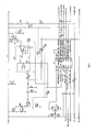
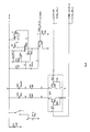
- a circuit of a smoke alarm device of the invention comprises a microcontroller U1 ( Fig. 2 ), a smoke sensing chamber with a light emitting diode IRED ( Fig. 2 ) and a photo detector PD (Figl), a 3V lithium cell ( Fig. 4 ), a piezoelectric horn HORN ( Fig. 4 ) and LED indicators LED 1 and LED 2 ( Fig. 4 ).
- the main functions programmed into U1 are as follows.
- Capacitors C1 and C2 as shown give attenuation of high frequency noise (C2) and also filtering of DC and low frequency noise (C1 with resistor R9A) caused by high levels of ambient light, for example from sunshine or 100 Hz light from fluorescent tubes entering the optical chamber. Because C1 and the associated resistor R9A are connected in series between two op-amps it filters the DC and low frequency noise, and because C2 is connected across the gain setting resistor of another op-amp it is very effective at filtering out high frequency noise.
- the device also includes an RF module for interconnecting to other alarms and for user remote control.
- a further feature of the invention is to give fast response to fires but at the same time to keep the current drawn from the battery to a minimum. Pulsing the IRED with the high current needed (typically 250 mA or higher) is a major part of the drain on the battery.
- the IRED is pulsed every 16 seconds. This would therefore be expected to have a response time of between 3 and 19 seconds. The 19 seconds can be too long in some circumstances and to overcome this, the IRED pulsing is speeded up as the smoke increases in the chamber as follows. This ensures that during fire tests, in which the smoke builds up in times of the order of less than 60 seconds, the device responds rapidly. This can be very beneficial in a critical fire situation. It is also beneficial in comparison fire tests between competitive smoke alarms.
- the device addresses the problem of achieving stable smoke sensitivity over the voltage range as follows.
- the IC U2 is a quad operational amplifier (op-amp) and is used to amplify the low level voltage signal from the photodiode PD (bottom right corner of Fig 1 ). There are four op-amps as illustrated, the gain values of which are included in Fig. 1 . The op-amps step up the voltage from one to the other, conditioning the voltage for U1, particularly for analogue-to-digital conversion.
- U2 provides two outputs as shown in the top left corner of Fig. 1 , namely O/P 1 and O/P 2. The gains for these two outputs are 796 and 140.
- the quad op-amp U2 amplifies the photodiode (PD) signal.
- the full gain of the four stages is 796 and the lower gain of the first three stages is 140.
- the 14.25mV when amplified by 140 gives a signal of 1.99 Volts which is below lowest supply voltage.
- the circuit addresses the problem of varying battery voltage (3.6V down to 2.2V) causing differing light output from the IRED.
- the band gap precision voltage reference U3, ( Fig 2 ) provides a stable voltage level Vref of 1.22V at the base of Q3.
- the capacitor C14 stores the battery voltage.
- the microcontroller U1, using pin 3 turns on the PNP transistor in QP2 which in turn biases on the voltage reference U3 which generates Vref (1.22 Volts) at the base of the IRED driver transistor Q3.
- the circuit configuration has the added benefit that is gives an inherent temperature compensation of close to - 0.8% per degree C to overcome the reduction in the photon output of the IRED as the temperature increases (and vice versa).
- the internal microcontroller circuit has two clocks. There is a 4MHz clock with a tolerance of 2% which has little temperature variation and draws 0.5mA. This is only turned on as needed to minimize power utilisation and hence prolong battery life.
- the second clock is a watchdog timer which draws less current and is sensitive to temperature variation.
- the processor U1 is programmed to normally use the watchdog timer and to switch to use of the first clock periodically to measure the period of the watchdog timer to deduce the temperature from the change in this period. If extra temperature compensation is needed, then the output voltage from the op-amps is multiplied by an appropriate constant to allow for this, prior to further analysis of the smoke chamber signal.
- the problem with the large piezo current pulse on start-up is solved by the microcontroller turning on the transistor Q1 for about 300 microseconds (approximately the period of the piezo disc, which has a nominal resonant frequency of 3000Hz). It then interrupts the drive to Q1 for about 150 microseconds and then turns the drive on continuously thereafter.
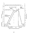
- Fig. 5 shows the very high level of dust compensation that the invention allows i.e. it can tolerate 8 times the level of dust that would cause an uncompensated device to give an alarm.
- a dust compensation of just 2 or 3 are typical of the present state of the prior art.
- the following is the manner in which the device deals with the problems of nuisance alarms from activity such as cooking and also from dust build-up in the optical chamber.
- the user presses the test/hush button and the device is de-sensitised for 10 minutes. If the smoke clears the device will not go back into alarm and the "problem" is solved. However, if the device goes back into alarm, pressing the test/hush button (within 4 minutes) will again de-sensitise the device for 10 minutes, but now towards the end of this second ten minutes, the device will "quickly" compensate for the contamination in the chamber within a few minutes. In standby this normally takes hours, to ensure it does not inadvertently compensate for a slowly developing fire.
- the user presses the hush/test button within 4 minutes of it going back into alarm) for a third time.
- the smoke alarm silences the horn for 8 hours, (provided the chamber continues to sense an alarm condition). If the alarm condition clears (e.g. due to the chamber being cleaned) for at least 5 minutes continuously (to ensure the alarm is not being caused by "intermittent" contamination such as a fibre wafting in and out of the sensitive part of the chamber) then the smoke alarm goes back to normal standby.
- the device will give two short beeps (10 millisec long) about 0.5 seconds apart every 10 minutes to gently remind the user that the device is not operational and should be replaced. This also allows it to comply with the standard EN14604 alarm silence facility clause that states "continuous operation of the alarm silence control shall not lead to the smoke alarm being de-sensitised for more than 15 minutes without an audible warning being given".
- the device After the 8 hours the device will go back into its alarm and now pressing the test/hush button (within 4 minutes) will silence it as in 3 above for a further 24 hours (with 2 beeps every 10 minutes). If the smoke chamber contamination is cleaned the device will reset to normal sensitivity.
- the hush could be enabled by remotely using a hardwired switch or by using a radiolink switch.
- Some standards allow radio transmitting devices to automatically silence the horns once the alarm has been given for at least 30 minutes. This is to preserve battery life and is based on the premise that users will have taken appropriate action (e.g. by evacuating the premises or by extinguishing the fire) well before the 30 minutes of alarm has elapsed.
- a further problem is that if a device (in say a property with 10 alarms) is giving beeps just once a minute it can be very tedious and time-consuming to locate it, and indeed some inspectors in a hurry might replace all the devices rather than spend the time to identify the problem device.
- Some manufacturers have test apparatus for field engineers for testing devices after they have been removed from the ceiling. This is effective but costly as the devices have to be removed from the ceiling and special unique apparatus for each type of alarm is required.
- the controller U1 is programmed to give the inspector, using simple indicators already in the alarm, comprehensive data to allow them to quickly identify defective devices and also devices that are likely to become defective prior to the next inspection period (normally inspections are done annually).
- the main defects which need to be identified are a partially contaminated device, devices where the battery voltage is close to the low battery trip point and badly sited alarms giving nuisance alarms due to being too close to a kitchen or bathroom.
- the inspector presses the test button and the information in the trouble shooting diagnostics section giving the state of the alarm. This also checks if the device is going to give low battery beeps or chamber beeps within about 12 to 18 months.
- the device of the invention in various embodiments has a comprehensive set of indicators (sounder, red LED and yellow LED) to help the user gain the maximum benefit from the alarms with no, or minimal nuisance effects (such as horn beeps or LED flashes). These are explained below as a set out in the user instructions.
- the device In normal operation, the device is silent and there are no LED flashes (which could be intrusive in a dark bedroom at night).
- the user should press the test button weekly to check the sensor, electronics and horn; and also to familiarise the occupants with the sound of the alarms.
- the horn will start softly so as to reduce exposure to excessive noise levels.
- the red LED on the devices sensing smoke flashes rapidly (every 1 ⁇ 2 second) to indicate if it is the device sensing fire.
- the user presses the large test button e.g. with a broom handle
- the large test button e.g. with a broom handle
- the battery will last over 10 years before it becomes partially depleted.
- electronic self testing indicates that the battery is becoming low the device will beep and the red LED will flash at the same time (about every 32 seconds) to warn the user. This indicates that the device must be replaced. If it is not convenient to replace the device immediately, then the user can press the test button to silence the low battery beeps and stop the red LED flashing for 12 hours. This can be repeated as required.
- the device goes into alarm for a third time, the device is excessively contaminated and must be replaced. If it is not convenient to replace it immediately, pressing the test button within 4 minutes of it going into alarm (for the third time) will silence the device for 12 hours - however it will give two short beeps (1 ⁇ 2 second apart) every 10 minutes to remind the user it has been disabled. If the contamination clears the device will return to normal operation.
- the device In the unlikely event of the smoke sensing chamber becoming defective, the device will give a short beep with a yellow LED flash every 32 seconds. The device must then be replaced. If it is not convenient to replace it immediately, pressing the test button will silence the beeps and stop the yellow LED flashing for 12 hours. This can be repeated as required.
- a device may alarm for a short period (e.g. due to a small puff of cooking fumes or vapour from a bathroom). While the horn is sounding the red LED will flashing every 1 ⁇ 2 seconds. When the horn stops the red LED will give two short flashes (0.5 seconds apart) every 16 seconds for 24 hours. This can be particularly beneficial in identifying a device that gave a short alarm during the night.
- test button After the 24 hours has elapsed, a device that has been in alarm can still be identified.
- the test button When the test button is pressed, the horn will sound with rapid chirping (instead of its normal sound). This can be invaluable to a maintenance person troubleshooting a property some days, or even months later - as it can highlight that a particular device should be moved further from a kitchen or bathroom or that a particular device has an intermittent defect.
- This pressing of the test button also resets the two memory features.
- the low battery voltage trip point is increased, by the expected voltage drop over the following year (typically by 40 mV to 100 mV) and if the battery voltage is less than this more severe requirement when the test button is pressed, the horn will sound in the normal way but the yellow light will flash rapidly to indicate the battery is likely to give low battery beeps within a year. This allows the inspector to replace the alarm. The user will therefore not be disturbed by beeps during the following year and also the service company will not be called out to replace the device.
- Horn start up pulse significantly reduced by inducing the oscillator to reach the resonant frequency more quickly.
- the invention also provides a simple way of identifying if a device is significantly contaminated and likely to go into continuous alarm within 12 to 18 months by pressing the test button. It also provides a simple way if identifying if the device has been silenced for 12 hours due to a contamination nuisance alarm by pressing the test button.
- a further advantageous aspect is flashing the LED and the change in the horn sound on button test to find devices that have been in alarm.
Landscapes
- Physics & Mathematics (AREA)
- General Physics & Mathematics (AREA)
- Engineering & Computer Science (AREA)
- Computer Security & Cryptography (AREA)
- Chemical & Material Sciences (AREA)
- Analytical Chemistry (AREA)
- Business, Economics & Management (AREA)
- Emergency Management (AREA)
- Fire-Detection Mechanisms (AREA)
Claims (16)
- Un procédé d'exploitation d'un dispositif d'alarme de fumée comprenant :un détecteur de fumée optique comprenant une diode électroluminescente (IRED) et un photodétecteur (PD) monté dans une chambre,un circuit avec un processeur (U1), une interface utilisateur et un émetteur sonore (HORN), où le processeur est adapté de façon à amener l'émetteur lumineux (IRED) à être activé par un circuit d'attaque, le procédé étant exécuté par le processeur et comprenant les opérations suivantes :à réception d'une commande utilisateur, l'entrée dans un mode désensibilisé pendant une première période,si le processeur revient en mode alarme après la première période et en réponse à une commande utilisateur, l'entrée dans une deuxième période désensibilisée, l'exécution automatique d'un recalibrage de compensation de poussière dans ladite deuxième période ou une période désensibilisée suivante, le recalibrage étant mis en oeuvre pendant une durée inférieure à vingt minutes, etla direction de l'émission d'un indicateur indiquant que le dispositif est désensibilisé pendant qu'il se trouve dans le mode désensibilisé.
- Un procédé selon la Revendication 1, où le processeur cesse d'envoyer une alarme pendant une période dépassant 4 heures s'il exécute une compensation de poussière et également s'il reçoit une instruction de silence provenant d'un utilisateur.
- Un procédé selon l'une quelconque des Revendications précédentes, où le processeur augmente une vitesse d'activation d'émetteur lumineux en réponse à une détection accrue de fumée.
- Un procédé selon la Revendication 3, où le processeur (U1) déclenche une durée d'inter-activation suivante plus courte dans le cas où le niveau de fumée atteint successivement des seuils plus élevés jusqu'à ce qu'un niveau d'alarme soit atteint.
- Un procédé selon l'une quelconque des Revendications précédentes, où le processeur génère une sortie destinée à l'identification du dispositif parmi un groupe de dispositifs, dans lequel le processeur active une combinaison d'un émetteur sonore et de deux indicateurs clignotants de façon à indiquer un état de batterie faible ou une panne, ou une chambre contaminée, ou si le dispositif a été en alarme auparavant en réponse à une pression sur un bouton de test par un utilisateur, où ladite période temporelle est de l'ordre de 0,2 seconde à environ 0,75 seconde entre clignotements.
- Un procédé selon l'une quelconque des Revendications précédentes, où le processeur (U1) identifie si le dispositif s'approche d'un état de batterie faible ou d'un état de contamination par la poussière, et génère une sortie indiquant ce cas de figure, où le processeur est adapté de façon à générer ladite sortie s'il est prévu que l'état apparaîtra dans période temporelle de 6 à 24 mois, de préférence de 12 à 18 mois.
- Un procédé selon la Revendication 6, où ladite sortie est générée en réponse à une pression sur un bouton de test par un utilisateur.
- Un procédé selon les Revendications 6 ou 7, où le processeur (U1) applique un test de batterie plus rigoureux de façon à déterminer si le dispositif s'approche d'un état de batterie faible.
- Un procédé selon la Revendication 8, où ledit test est exécuté uniquement au cours d'une interaction d'utilisateur telle qu'un bouton de test, permettant ainsi d'éviter le problème d'une indication prématurée causée par une température basse.
- Un dispositif d'alarme de fumée comprenant :un détecteur de fumée optique comprenant une diode électroluminescente (IRED) et un photodétecteur (PD) monté dans une chambre,un circuit avec un processeur (U1), une interface utilisateur et un émetteur sonore (HORN), où le processeur est adapté de façon à amener l'émetteur lumineux (IRED) à être activé par un circuit d'attaque, où le processeur est adapté de façon à exécuter le procédé selon l'une quelconque des Revendications 1 à 8.
- Un dispositif d'alarme de fumée selon la Revendication 10, où le circuit comprend une source de courant destinée à permettre à l'émetteur lumineux de maintenir un courant uniforme au travers dudit émetteur, où ladite source de courant comprend un transistor de commutateur de commande d'émetteur lumineux (Q3) en série avec l'émetteur lumineux, une résistance (R25) raccordée entre le commutateur d'émetteur lumineux (Q3) et la terre, une diode (U3) fournissant une référence de tension pour une base d'un commutateur d'émetteur lumineux (Q3) et un commutateur de commande (QP2) relié à la base du commutateur d'émetteur lumineux (Q3), et un moyen dans le processeur (U1) d'activation du commutateur de commande (QP2).
- Un dispositif d'alarme de fumée selon les Revendications 10 ou 11, où le circuit comprend des composants de gain (U2) destinés à fournir différents gains provenant du détecteur de lumière, et le processeur est adapté de façon à choisir un gain approprié, où les composants de gain comprennent une pluralité d'amplificateurs opérationnels inter-raccordés, dans lesquels une capacité (C2) sur la résistance de réglage de gain d'un amplificateur opérationnel fournit une atténuation de bruit haute fréquence (C2) et une capacité (C1) en série entre deux amplificateurs opérationnels fournit un filtrage de courant c.c. et d'un bruit basse fréquence provoqué par une lumière ambiante.
- Un dispositif d'alarme de fumée selon les Revendications 11 ou 12, où le processeur est adapté de façon à choisir dynamiquement une valeur de gain en fonction de variations induites par la température dans la sortie lumineuse de l'émetteur lumineux.
- Un dispositif d'alarme de fumée selon l'une quelconque des Revendications 11 à 13, où les composants de l'étage de gain (U2) comprennent quatre amplificateurs opérationnels agencés de façon à amplifier la sortie de détecteur, où un gain complet est fourni par les quatre étages et un gain plus faible est fourni par les trois premiers étages, et où le processeur (U1) est adapté de façon à utiliser le gain élevé jusqu'à ce que le signal de sortie du photodétecteur se trouve juste sous l'alimentation électrique et ensuite de façon à commuter vers le gain faible de façon à garantir que le signal le plus faible à amplifier possède une sortie provenant des étages de gain élevé qui soit suffisamment grande pour donner un rapport signal sur bruit cible pour à la fois le bruit généré de manière interne et le bruit généré de manière externe.
- Un dispositif d'alarme de fumée selon l'une quelconque des Revendications 10 à 14, où le circuit est adapté de façon à compenser une réduction de la sortie de photons de l'émetteur lumineux lorsque la température augmente, où le circuit comprend une première horloge possédant une variation de température faible mais une consommation électrique élevée et une horloge de surveillance qui possède une variation de température plus élevée mais une consommation électrique faible, et le processeur est adapté de façon à utiliser normalement l'horloge de surveillance et à commuter de façon à utiliser la première horloge périodiquement de façon à mesurer la période de l'horloge de surveillance de façon à déduire la température à partir du changement observé au cours de cette période.
- Un dispositif d'alarme de fumée selon l'une quelconque des Revendications 10 à 15, où l'émetteur sonore (HORN) comprend une membrane piézoélectrique et le processeur (U1) est adapté de façon à interrompre un circuit d'attaque vers l'émetteur sonore au démarrage, où le circuit d'attaque est interrompu pendant une durée égale à approximativement la période de la membrane piézoélectrique.
Applications Claiming Priority (1)
| Application Number | Priority Date | Filing Date | Title |
|---|---|---|---|
| IE20100130 | 2010-03-04 |
Publications (2)
| Publication Number | Publication Date |
|---|---|
| EP2363844A1 EP2363844A1 (fr) | 2011-09-07 |
| EP2363844B1 true EP2363844B1 (fr) | 2013-04-17 |
Family
ID=44000707
Family Applications (1)
| Application Number | Title | Priority Date | Filing Date |
|---|---|---|---|
| EP20110394005 Active EP2363844B1 (fr) | 2010-03-04 | 2011-03-04 | Améliorations associées à des dispositifs de détecteurs de fumée |
Country Status (2)
| Country | Link |
|---|---|
| EP (1) | EP2363844B1 (fr) |
| IE (1) | IE20110103A1 (fr) |
Families Citing this family (3)
| Publication number | Priority date | Publication date | Assignee | Title |
|---|---|---|---|---|
| US9019112B2 (en) | 2012-07-13 | 2015-04-28 | Walter Kidde Portable Equipment, Inc. | Systems and methods for optimizing low battery indication in alarms |
| CN111263958B (zh) | 2017-10-30 | 2022-05-27 | 开利公司 | 检测器装置中的补偿器 |
| US12272231B1 (en) | 2023-10-01 | 2025-04-08 | Climax Technology Co., Ltd. | Smoke detection method with temperature and dust compensation |
Family Cites Families (5)
| Publication number | Priority date | Publication date | Assignee | Title |
|---|---|---|---|---|
| US4420746A (en) * | 1979-07-27 | 1983-12-13 | Malinowski William J | Self-calibrating smoke detector and method |
| US4792797A (en) * | 1987-03-05 | 1988-12-20 | Seatt Corporation | Smoke detector having variable level sensitivity |
| EP1098284B1 (fr) | 1999-11-05 | 2004-05-06 | E.I. Technology Limited | Dispositif d'alarme de fumée |
| US6753786B1 (en) * | 2000-08-11 | 2004-06-22 | Walter Kidde Portable Equipment, Inc. | Microprocessor-based combination smoke and carbon monoxide detector having intelligent hush feature |
| GB2398155B (en) * | 2003-02-04 | 2005-11-30 | Kidde Ip Holdings Ltd | Hazard detection |
-
2011
- 2011-03-04 IE IE20110103A patent/IE20110103A1/en not_active Application Discontinuation
- 2011-03-04 EP EP20110394005 patent/EP2363844B1/fr active Active
Also Published As
| Publication number | Publication date |
|---|---|
| IE20110103A1 (en) | 2011-09-14 |
| EP2363844A1 (fr) | 2011-09-07 |
Similar Documents
| Publication | Publication Date | Title |
|---|---|---|
| US8952822B2 (en) | Use of optical reflectance proximity detector for nuisance mitigation in smoke alarms | |
| CN102568145B (zh) | 具有在低电池电压时抑制声告警的装置的散光火灾报警器 | |
| CN103080988B (zh) | 光学烟雾检测器 | |
| EP1098284B1 (fr) | Dispositif d'alarme de fumée | |
| US4814748A (en) | Temporary desensitization technique for smoke alarms | |
| EP2363844A1 (fr) | Améliorations associées à des dispositifs de détecteurs de fumée | |
| JP4391046B2 (ja) | 火災感知器 | |
| JP4862831B2 (ja) | 警報器 | |
| JPH11509341A (ja) | 光電式煙感知器の改良 | |
| JP4882994B2 (ja) | 警報器 | |
| JP3945756B2 (ja) | 火災感知器 | |
| JP2010073045A (ja) | 火災警報器 | |
| JP5860229B2 (ja) | 警報器 | |
| JPH06325273A (ja) | 紫外線式感知器 | |
| KR100655369B1 (ko) | 청소알림기능이 부가된 연감지장치 | |
| JPS5924479B2 (ja) | 光電式煙感知器 | |
| JPH07320173A (ja) | 光電式煙感知器及び火災感知器 | |
| JPS6148758B2 (fr) | ||
| JPS6148759B2 (fr) | ||
| JPH02311997A (ja) | 光電式煙感知器 | |
| JP2003196756A (ja) | 火災感知器 | |
| JP2501374B2 (ja) | 熱線式検知器 | |
| JPS59160294A (ja) | 試験装置を備えた火災感知器 | |
| KR200409592Y1 (ko) | 청소알림기능이 부가된 연감지장치 | |
| JP2022065389A (ja) | 火災検出装置、防災設備及び火災検出方法 |
Legal Events
| Date | Code | Title | Description |
|---|---|---|---|
| PUAI | Public reference made under article 153(3) epc to a published international application that has entered the european phase |
Free format text: ORIGINAL CODE: 0009012 |
|
| AK | Designated contracting states |
Kind code of ref document: A1 Designated state(s): AL AT BE BG CH CY CZ DE DK EE ES FI FR GB GR HR HU IE IS IT LI LT LU LV MC MK MT NL NO PL PT RO RS SE SI SK SM TR |
|
| AX | Request for extension of the european patent |
Extension state: BA ME |
|
| 17P | Request for examination filed |
Effective date: 20110823 |
|
| RIC1 | Information provided on ipc code assigned before grant |
Ipc: G08B 29/18 20060101ALN20121211BHEP Ipc: G08B 29/22 20060101ALI20121211BHEP Ipc: G08B 17/10 20060101AFI20121211BHEP |
|
| GRAP | Despatch of communication of intention to grant a patent |
Free format text: ORIGINAL CODE: EPIDOSNIGR1 |
|
| GRAS | Grant fee paid |
Free format text: ORIGINAL CODE: EPIDOSNIGR3 |
|
| GRAA | (expected) grant |
Free format text: ORIGINAL CODE: 0009210 |
|
| AK | Designated contracting states |
Kind code of ref document: B1 Designated state(s): AL AT BE BG CH CY CZ DE DK EE ES FI FR GB GR HR HU IE IS IT LI LT LU LV MC MK MT NL NO PL PT RO RS SE SI SK SM TR |
|
| REG | Reference to a national code |
Ref country code: GB Ref legal event code: FG4D |
|
| REG | Reference to a national code |
Ref country code: CH Ref legal event code: EP |
|
| REG | Reference to a national code |
Ref country code: IE Ref legal event code: FG4D |
|
| REG | Reference to a national code |
Ref country code: AT Ref legal event code: REF Ref document number: 607731 Country of ref document: AT Kind code of ref document: T Effective date: 20130515 |
|
| REG | Reference to a national code |
Ref country code: DE Ref legal event code: R096 Ref document number: 602011001402 Country of ref document: DE Effective date: 20130613 |
|
| REG | Reference to a national code |
Ref country code: NL Ref legal event code: T3 |
|
| REG | Reference to a national code |
Ref country code: AT Ref legal event code: MK05 Ref document number: 607731 Country of ref document: AT Kind code of ref document: T Effective date: 20130417 |
|
| REG | Reference to a national code |
Ref country code: LT Ref legal event code: MG4D |
|
| PG25 | Lapsed in a contracting state [announced via postgrant information from national office to epo] |
Ref country code: NO Free format text: LAPSE BECAUSE OF FAILURE TO SUBMIT A TRANSLATION OF THE DESCRIPTION OR TO PAY THE FEE WITHIN THE PRESCRIBED TIME-LIMIT Effective date: 20130717 Ref country code: FI Free format text: LAPSE BECAUSE OF FAILURE TO SUBMIT A TRANSLATION OF THE DESCRIPTION OR TO PAY THE FEE WITHIN THE PRESCRIBED TIME-LIMIT Effective date: 20130417 Ref country code: ES Free format text: LAPSE BECAUSE OF FAILURE TO SUBMIT A TRANSLATION OF THE DESCRIPTION OR TO PAY THE FEE WITHIN THE PRESCRIBED TIME-LIMIT Effective date: 20130728 Ref country code: IS Free format text: LAPSE BECAUSE OF FAILURE TO SUBMIT A TRANSLATION OF THE DESCRIPTION OR TO PAY THE FEE WITHIN THE PRESCRIBED TIME-LIMIT Effective date: 20130817 Ref country code: GR Free format text: LAPSE BECAUSE OF FAILURE TO SUBMIT A TRANSLATION OF THE DESCRIPTION OR TO PAY THE FEE WITHIN THE PRESCRIBED TIME-LIMIT Effective date: 20130718 Ref country code: PT Free format text: LAPSE BECAUSE OF FAILURE TO SUBMIT A TRANSLATION OF THE DESCRIPTION OR TO PAY THE FEE WITHIN THE PRESCRIBED TIME-LIMIT Effective date: 20130819 Ref country code: LT Free format text: LAPSE BECAUSE OF FAILURE TO SUBMIT A TRANSLATION OF THE DESCRIPTION OR TO PAY THE FEE WITHIN THE PRESCRIBED TIME-LIMIT Effective date: 20130417 Ref country code: SI Free format text: LAPSE BECAUSE OF FAILURE TO SUBMIT A TRANSLATION OF THE DESCRIPTION OR TO PAY THE FEE WITHIN THE PRESCRIBED TIME-LIMIT Effective date: 20130417 Ref country code: AT Free format text: LAPSE BECAUSE OF FAILURE TO SUBMIT A TRANSLATION OF THE DESCRIPTION OR TO PAY THE FEE WITHIN THE PRESCRIBED TIME-LIMIT Effective date: 20130417 Ref country code: SE Free format text: LAPSE BECAUSE OF FAILURE TO SUBMIT A TRANSLATION OF THE DESCRIPTION OR TO PAY THE FEE WITHIN THE PRESCRIBED TIME-LIMIT Effective date: 20130417 |
|
| PG25 | Lapsed in a contracting state [announced via postgrant information from national office to epo] |
Ref country code: LV Free format text: LAPSE BECAUSE OF FAILURE TO SUBMIT A TRANSLATION OF THE DESCRIPTION OR TO PAY THE FEE WITHIN THE PRESCRIBED TIME-LIMIT Effective date: 20130417 Ref country code: RS Free format text: LAPSE BECAUSE OF FAILURE TO SUBMIT A TRANSLATION OF THE DESCRIPTION OR TO PAY THE FEE WITHIN THE PRESCRIBED TIME-LIMIT Effective date: 20130417 Ref country code: CY Free format text: LAPSE BECAUSE OF FAILURE TO SUBMIT A TRANSLATION OF THE DESCRIPTION OR TO PAY THE FEE WITHIN THE PRESCRIBED TIME-LIMIT Effective date: 20130417 Ref country code: PL Free format text: LAPSE BECAUSE OF FAILURE TO SUBMIT A TRANSLATION OF THE DESCRIPTION OR TO PAY THE FEE WITHIN THE PRESCRIBED TIME-LIMIT Effective date: 20130417 Ref country code: BG Free format text: LAPSE BECAUSE OF FAILURE TO SUBMIT A TRANSLATION OF THE DESCRIPTION OR TO PAY THE FEE WITHIN THE PRESCRIBED TIME-LIMIT Effective date: 20130717 Ref country code: HR Free format text: LAPSE BECAUSE OF FAILURE TO SUBMIT A TRANSLATION OF THE DESCRIPTION OR TO PAY THE FEE WITHIN THE PRESCRIBED TIME-LIMIT Effective date: 20130417 |
|
| PG25 | Lapsed in a contracting state [announced via postgrant information from national office to epo] |
Ref country code: DK Free format text: LAPSE BECAUSE OF FAILURE TO SUBMIT A TRANSLATION OF THE DESCRIPTION OR TO PAY THE FEE WITHIN THE PRESCRIBED TIME-LIMIT Effective date: 20130417 Ref country code: SK Free format text: LAPSE BECAUSE OF FAILURE TO SUBMIT A TRANSLATION OF THE DESCRIPTION OR TO PAY THE FEE WITHIN THE PRESCRIBED TIME-LIMIT Effective date: 20130417 Ref country code: EE Free format text: LAPSE BECAUSE OF FAILURE TO SUBMIT A TRANSLATION OF THE DESCRIPTION OR TO PAY THE FEE WITHIN THE PRESCRIBED TIME-LIMIT Effective date: 20130417 Ref country code: CZ Free format text: LAPSE BECAUSE OF FAILURE TO SUBMIT A TRANSLATION OF THE DESCRIPTION OR TO PAY THE FEE WITHIN THE PRESCRIBED TIME-LIMIT Effective date: 20130417 |
|
| PLBE | No opposition filed within time limit |
Free format text: ORIGINAL CODE: 0009261 |
|
| STAA | Information on the status of an ep patent application or granted ep patent |
Free format text: STATUS: NO OPPOSITION FILED WITHIN TIME LIMIT |
|
| PG25 | Lapsed in a contracting state [announced via postgrant information from national office to epo] |
Ref country code: IT Free format text: LAPSE BECAUSE OF FAILURE TO SUBMIT A TRANSLATION OF THE DESCRIPTION OR TO PAY THE FEE WITHIN THE PRESCRIBED TIME-LIMIT Effective date: 20130417 Ref country code: RO Free format text: LAPSE BECAUSE OF FAILURE TO SUBMIT A TRANSLATION OF THE DESCRIPTION OR TO PAY THE FEE WITHIN THE PRESCRIBED TIME-LIMIT Effective date: 20130417 |
|
| 26N | No opposition filed |
Effective date: 20140120 |
|
| REG | Reference to a national code |
Ref country code: DE Ref legal event code: R097 Ref document number: 602011001402 Country of ref document: DE Effective date: 20140120 |
|
| PG25 | Lapsed in a contracting state [announced via postgrant information from national office to epo] |
Ref country code: LU Free format text: LAPSE BECAUSE OF FAILURE TO SUBMIT A TRANSLATION OF THE DESCRIPTION OR TO PAY THE FEE WITHIN THE PRESCRIBED TIME-LIMIT Effective date: 20140304 |
|
| REG | Reference to a national code |
Ref country code: CH Ref legal event code: PL |
|
| PG25 | Lapsed in a contracting state [announced via postgrant information from national office to epo] |
Ref country code: CH Free format text: LAPSE BECAUSE OF NON-PAYMENT OF DUE FEES Effective date: 20140331 Ref country code: LI Free format text: LAPSE BECAUSE OF NON-PAYMENT OF DUE FEES Effective date: 20140331 |
|
| REG | Reference to a national code |
Ref country code: FR Ref legal event code: PLFP Year of fee payment: 5 |
|
| REG | Reference to a national code |
Ref country code: DE Ref legal event code: R082 Ref document number: 602011001402 Country of ref document: DE Representative=s name: MITSCHERLICH, PATENT- UND RECHTSANWAELTE PARTM, DE Ref country code: DE Ref legal event code: R081 Ref document number: 602011001402 Country of ref document: DE Owner name: E.I. TECHNOLOGY, IE Free format text: FORMER OWNER: E.I. TECHNOLOGY LTD., SHANNON, COUNTY CLARE, IE |
|
| REG | Reference to a national code |
Ref country code: GB Ref legal event code: S117 Free format text: REQUEST FILED; REQUEST FOR CORRECTION UNDER SECTION 117 FILED ON 10 NOVEMBER 2015 |
|
| REG | Reference to a national code |
Ref country code: GB Ref legal event code: S117 Free format text: CORRECTIONS ALLOWED; REQUEST FOR CORRECTION UNDER SECTION 117 FILED ON 10 NOVEMBER 2015, ALLOWED ON 03 DECEMBER 2015 |
|
| REG | Reference to a national code |
Ref country code: FR Ref legal event code: PLFP Year of fee payment: 6 |
|
| REG | Reference to a national code |
Ref country code: FR Ref legal event code: RM Effective date: 20160125 |
|
| PG25 | Lapsed in a contracting state [announced via postgrant information from national office to epo] |
Ref country code: MT Free format text: LAPSE BECAUSE OF FAILURE TO SUBMIT A TRANSLATION OF THE DESCRIPTION OR TO PAY THE FEE WITHIN THE PRESCRIBED TIME-LIMIT Effective date: 20130417 |
|
| REG | Reference to a national code |
Ref country code: NL Ref legal event code: PD Owner name: E.I. TECHNOLOGY; IE Free format text: DETAILS ASSIGNMENT: VERANDERING VAN EIGENAAR(S), VERANDERING VAN DE JURIDISCHE ENTITEIT; FORMER OWNER NAME: E.I. TECHNOLOGY LIMITED Effective date: 20151027 |
|
| PG25 | Lapsed in a contracting state [announced via postgrant information from national office to epo] |
Ref country code: SM Free format text: LAPSE BECAUSE OF FAILURE TO SUBMIT A TRANSLATION OF THE DESCRIPTION OR TO PAY THE FEE WITHIN THE PRESCRIBED TIME-LIMIT Effective date: 20130417 |
|
| PG25 | Lapsed in a contracting state [announced via postgrant information from national office to epo] |
Ref country code: MC Free format text: LAPSE BECAUSE OF FAILURE TO SUBMIT A TRANSLATION OF THE DESCRIPTION OR TO PAY THE FEE WITHIN THE PRESCRIBED TIME-LIMIT Effective date: 20130417 |
|
| PG25 | Lapsed in a contracting state [announced via postgrant information from national office to epo] |
Ref country code: TR Free format text: LAPSE BECAUSE OF FAILURE TO SUBMIT A TRANSLATION OF THE DESCRIPTION OR TO PAY THE FEE WITHIN THE PRESCRIBED TIME-LIMIT Effective date: 20130417 Ref country code: HU Free format text: LAPSE BECAUSE OF FAILURE TO SUBMIT A TRANSLATION OF THE DESCRIPTION OR TO PAY THE FEE WITHIN THE PRESCRIBED TIME-LIMIT; INVALID AB INITIO Effective date: 20110304 |
|
| REG | Reference to a national code |
Ref country code: FR Ref legal event code: PLFP Year of fee payment: 7 |
|
| REG | Reference to a national code |
Ref country code: FR Ref legal event code: PLFP Year of fee payment: 8 |
|
| PG25 | Lapsed in a contracting state [announced via postgrant information from national office to epo] |
Ref country code: MK Free format text: LAPSE BECAUSE OF FAILURE TO SUBMIT A TRANSLATION OF THE DESCRIPTION OR TO PAY THE FEE WITHIN THE PRESCRIBED TIME-LIMIT Effective date: 20130417 |
|
| PG25 | Lapsed in a contracting state [announced via postgrant information from national office to epo] |
Ref country code: AL Free format text: LAPSE BECAUSE OF FAILURE TO SUBMIT A TRANSLATION OF THE DESCRIPTION OR TO PAY THE FEE WITHIN THE PRESCRIBED TIME-LIMIT Effective date: 20130417 |
|
| REG | Reference to a national code |
Ref country code: DE Ref legal event code: R082 Ref document number: 602011001402 Country of ref document: DE Representative=s name: MITSCHERLICH, PATENT- UND RECHTSANWAELTE PARTM, DE Ref country code: DE Ref legal event code: R081 Ref document number: 602011001402 Country of ref document: DE Owner name: E.I. TECHNOLOGY UNLIMITED COMPANY, IE Free format text: FORMER OWNER: E.I. TECHNOLOGY, SHANNON, IE |
|
| REG | Reference to a national code |
Ref country code: BE Ref legal event code: HC Owner name: E.I. TECHNOLOGY UNLIMITED COMPANY; IE Free format text: DETAILS ASSIGNMENT: CHANGE OF OWNER(S), CHANGEMENT DE NOM DU PROPRIETAIRE; FORMER OWNER NAME: E.I. TECHNOLOGY LIMITED Effective date: 20190220 Ref country code: BE Ref legal event code: HC Owner name: E.I. TECHNOLOGY; IE Free format text: DETAILS ASSIGNMENT: CHANGE OF OWNER(S), CHANGEMENT NOM PROPRIETAIRE, RECTIFICATION; FORMER OWNER NAME: E.I. TECHNOLOGY LIMITED Effective date: 20151201 |
|
| REG | Reference to a national code |
Ref country code: NL Ref legal event code: HC Owner name: E.I. TECHNOLOGY UNLIMITED COMPANY; IE Free format text: DETAILS ASSIGNMENT: CHANGE OF OWNER(S), CHANGE OF OWNER(S) NAME; FORMER OWNER NAME: E.I. TECHNOLOGY Effective date: 20190226 |
|
| P01 | Opt-out of the competence of the unified patent court (upc) registered |
Effective date: 20230419 |
|
| PGFP | Annual fee paid to national office [announced via postgrant information from national office to epo] |
Ref country code: GB Payment date: 20260204 Year of fee payment: 16 |
|
| PGFP | Annual fee paid to national office [announced via postgrant information from national office to epo] |
Ref country code: DE Payment date: 20260209 Year of fee payment: 16 Ref country code: IE Payment date: 20260204 Year of fee payment: 16 |
|
| PGFP | Annual fee paid to national office [announced via postgrant information from national office to epo] |
Ref country code: BE Payment date: 20260323 Year of fee payment: 16 |
|
| PGFP | Annual fee paid to national office [announced via postgrant information from national office to epo] |
Ref country code: NL Payment date: 20260323 Year of fee payment: 16 |
|
| PGFP | Annual fee paid to national office [announced via postgrant information from national office to epo] |
Ref country code: FR Payment date: 20260226 Year of fee payment: 16 |