EP2364429B1 - Procédé de qualification de taches lumineuses pour des mesures optiques et instrument de mesure employant le procédé de qualification de taches lumineuses - Google Patents
Procédé de qualification de taches lumineuses pour des mesures optiques et instrument de mesure employant le procédé de qualification de taches lumineuses Download PDFInfo
- Publication number
- EP2364429B1 EP2364429B1 EP09752695A EP09752695A EP2364429B1 EP 2364429 B1 EP2364429 B1 EP 2364429B1 EP 09752695 A EP09752695 A EP 09752695A EP 09752695 A EP09752695 A EP 09752695A EP 2364429 B1 EP2364429 B1 EP 2364429B1
- Authority
- EP
- European Patent Office
- Prior art keywords
- light
- light spots
- light spot
- spots
- group
- Prior art date
- Legal status (The legal status is an assumption and is not a legal conclusion. Google has not performed a legal analysis and makes no representation as to the accuracy of the status listed.)
- Not-in-force
Links
- 238000000034 method Methods 0.000 title claims description 117
- 230000003287 optical effect Effects 0.000 title claims description 29
- 238000005259 measurement Methods 0.000 title description 63
- 238000004422 calculation algorithm Methods 0.000 claims description 47
- 210000001747 pupil Anatomy 0.000 claims description 29
- 230000008569 process Effects 0.000 claims description 10
- 238000012545 processing Methods 0.000 claims description 3
- 210000001508 eye Anatomy 0.000 description 47
- 238000012876 topography Methods 0.000 description 26
- 230000011514 reflex Effects 0.000 description 18
- 210000000695 crystalline len Anatomy 0.000 description 15
- 208000002177 Cataract Diseases 0.000 description 13
- 238000004364 calculation method Methods 0.000 description 13
- 210000004087 cornea Anatomy 0.000 description 13
- 238000012360 testing method Methods 0.000 description 11
- 230000004075 alteration Effects 0.000 description 8
- 230000000875 corresponding effect Effects 0.000 description 7
- 238000004458 analytical method Methods 0.000 description 5
- 238000009826 distribution Methods 0.000 description 5
- 230000000694 effects Effects 0.000 description 5
- 238000012797 qualification Methods 0.000 description 5
- 208000003556 Dry Eye Syndromes Diseases 0.000 description 4
- 206010013774 Dry eye Diseases 0.000 description 4
- 230000002547 anomalous effect Effects 0.000 description 4
- 230000004397 blinking Effects 0.000 description 4
- 230000001575 pathological effect Effects 0.000 description 4
- 239000000523 sample Substances 0.000 description 4
- 238000012512 characterization method Methods 0.000 description 3
- 238000010276 construction Methods 0.000 description 3
- 230000007717 exclusion Effects 0.000 description 3
- 210000000720 eyelash Anatomy 0.000 description 3
- 210000001525 retina Anatomy 0.000 description 3
- 229920006395 saturated elastomer Polymers 0.000 description 3
- 208000034699 Vitreous floaters Diseases 0.000 description 2
- 201000009310 astigmatism Diseases 0.000 description 2
- 230000009286 beneficial effect Effects 0.000 description 2
- 230000008901 benefit Effects 0.000 description 2
- 230000001684 chronic effect Effects 0.000 description 2
- 230000001010 compromised effect Effects 0.000 description 2
- 230000002596 correlated effect Effects 0.000 description 2
- 238000011156 evaluation Methods 0.000 description 2
- 230000006870 function Effects 0.000 description 2
- 230000007246 mechanism Effects 0.000 description 2
- 230000002093 peripheral effect Effects 0.000 description 2
- 230000002207 retinal effect Effects 0.000 description 2
- 239000013598 vector Substances 0.000 description 2
- 208000024813 Abnormality of the eye Diseases 0.000 description 1
- 206010007772 Cataract conditions Diseases 0.000 description 1
- 244000050403 Iris x germanica Species 0.000 description 1
- 244000182022 Salvia sclarea Species 0.000 description 1
- 235000002911 Salvia sclarea Nutrition 0.000 description 1
- 230000005856 abnormality Effects 0.000 description 1
- 208000013715 atelosteogenesis type I Diseases 0.000 description 1
- 230000000903 blocking effect Effects 0.000 description 1
- 230000001934 delay Effects 0.000 description 1
- 230000007613 environmental effect Effects 0.000 description 1
- 210000000744 eyelid Anatomy 0.000 description 1
- 230000036039 immunity Effects 0.000 description 1
- 238000007689 inspection Methods 0.000 description 1
- 238000004519 manufacturing process Methods 0.000 description 1
- 238000013507 mapping Methods 0.000 description 1
- 238000000691 measurement method Methods 0.000 description 1
Images








Classifications
-
- G—PHYSICS
- G01—MEASURING; TESTING
- G01B—MEASURING LENGTH, THICKNESS OR SIMILAR LINEAR DIMENSIONS; MEASURING ANGLES; MEASURING AREAS; MEASURING IRREGULARITIES OF SURFACES OR CONTOURS
- G01B11/00—Measuring arrangements characterised by the use of optical techniques
- G01B11/24—Measuring arrangements characterised by the use of optical techniques for measuring contours or curvatures
- G01B11/25—Measuring arrangements characterised by the use of optical techniques for measuring contours or curvatures by projecting a pattern, e.g. one or more lines, moiré fringes on the object
- G01B11/2513—Measuring arrangements characterised by the use of optical techniques for measuring contours or curvatures by projecting a pattern, e.g. one or more lines, moiré fringes on the object with several lines being projected in more than one direction, e.g. grids, patterns
-
- A—HUMAN NECESSITIES
- A61—MEDICAL OR VETERINARY SCIENCE; HYGIENE
- A61B—DIAGNOSIS; SURGERY; IDENTIFICATION
- A61B3/00—Apparatus for testing the eyes; Instruments for examining the eyes
- A61B3/10—Objective types, i.e. instruments for examining the eyes independent of the patients' perceptions or reactions
- A61B3/1015—Objective types, i.e. instruments for examining the eyes independent of the patients' perceptions or reactions for wavefront analysis
-
- A—HUMAN NECESSITIES
- A61—MEDICAL OR VETERINARY SCIENCE; HYGIENE
- A61B—DIAGNOSIS; SURGERY; IDENTIFICATION
- A61B3/00—Apparatus for testing the eyes; Instruments for examining the eyes
- A61B3/10—Objective types, i.e. instruments for examining the eyes independent of the patients' perceptions or reactions
- A61B3/107—Objective types, i.e. instruments for examining the eyes independent of the patients' perceptions or reactions for determining the shape or measuring the curvature of the cornea
-
- G—PHYSICS
- G01—MEASURING; TESTING
- G01M—TESTING STATIC OR DYNAMIC BALANCE OF MACHINES OR STRUCTURES; TESTING OF STRUCTURES OR APPARATUS, NOT OTHERWISE PROVIDED FOR
- G01M11/00—Testing of optical apparatus; Testing structures by optical methods not otherwise provided for
- G01M11/02—Testing optical properties
- G01M11/0242—Testing optical properties by measuring geometrical properties or aberrations
- G01M11/0257—Testing optical properties by measuring geometrical properties or aberrations by analyzing the image formed by the object to be tested
- G01M11/0264—Testing optical properties by measuring geometrical properties or aberrations by analyzing the image formed by the object to be tested by using targets or reference patterns
Definitions
- This invention pertains to devices and methods for performing optical measurements using a plurality of light spots, and more particularly, to a method of qualifying light spots for use for optical measurements by a measurement instrument, and a measurement instrument employing such a method of qualifying the light spots that are employed in its measurements.
- FIG. 1 illustrates some principal elements of a basic configuration of a Shack-Hartmann wavefront sensor 100.
- Shack-Hartmann wavefront sensor 100 comprises a micro-optic lenslet array 110 and an optical detector 120.
- the optical detector 120 comprises a pixel array, for example, a charge-coupled device (CCD) camera or CMOS array.
- CCD charge-coupled device
- lenslet array 110 dissect an incoming wavefront and create a pattern of light spots 130 that fall onto optical detector 120.
- lenslet array 110 includes hundreds or thousands of lenslets, each on the size scale of a hundred microns.
- optical detector 120 typically comprises many pixels (e.g., 400 pixels) for each lenslet in lenslet array 110.
- Shack-Hartmann sensor 100 is assembled such that the pixel array 120 lies in the focal plane of lenslet array 110.
- Shack-Hartmann wavefront sensor 100 uses the fact that light travels in a straight line to measure the wavefront of light. By sensing the positions of light spots 130, the propagation vector of the sampled light can be calculated for each lenslet of lenslet array 110. The wavefront of the received light can be reconstructed from these vectors.
- a system includes two or more optical measurement devices, for example, a combined system including both a wavefront sensor and a topographer.
- the wavefront sensor 100 some optical system is employed to deliver a wavefront onto lenslet array 110, which samples the wavefront over the tiny regions of each lenslet.
- the lenslets are much smaller than the wavefront variation.
- isoplanatic as the condition where the wavefront is well approximated by a plane wave over an area the size of a lenslet.
- the wavefront is preferably isoplanatic over the sampled region.
- a reference beam (e.g., a plane wave) is first imaged onto lenslet array 110 and the locations of the resultant light spots ("reference locations") on detector array 120 is recorded. Then, a wavefront of interest is imaged onto lenslet array 110, and the locations of the light spots on detector array 120 produced by the wavefront of interest is recorded and compared against the reference locations.
- a reference beam e.g., a plane wave
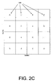
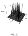
- FIGs. 2A-F illustrate an idealized example of this process where a reference beam and a wavefront of interest are imaged onto a detector array of a wavefront sensor.
- This idealization shows the process of measuring a spherical wave with a wavefront sensor with just 16 lenslets.
- the first step as represented by the FIGs. 2A-2C , is to measure a plane wave and measure the corresponding series of light spot locations 210 which are used as reference locations 220.
- the next step, as depicted in FIGs. 2D-2F is to introduce a wavefront of interest and determine the shifts in the locations 240 of the light spots 230 from their reference locations 220.
- the wavefront is not isoplanatic, the quality of the light spot erodes rapidly and it becomes more difficult to determine the location.
- the isoplanatic condition is satisfied and where the light spot shift is consistent with the small angle approximation of Fresnel, then the light spot shift is exactly proportional to the average of the wavefront slope over the lenslet.
- the incident wavefront is then reconstructed from the measurements of the average of the slopes for the hundreds or thousands of lenslets in the lenslet array.
- Shack-Hartmann wavefront sensors are in the field of ophthalmic aberrometry.
- a measurement instrument employing a Shack-Hartmann wavefront sensor injects near infrared light into a patient's eye which focuses on the retina and scatters back toward the instrument. This light is imaged onto the Shack-Hartmann lenslet array, and each lenslet in the lenslet array focuses the local portion of the incident light it intercepts onto the detector array, as described above.
- Data pertaining to the locations of the light spots is used to derive slope information using a least squares fit method, and thereby to construct the wavefront of the received light.
- the quality of the fit data usually evaluated using Zemike coefficients, is affected by the quality of the light spot location data, and every effort is made to ensure the data quality is adequate to the measurement accuracy and precision requirements.
- FIG. 3 shows a typical raw image from a wavefront sensor.
- the nominally rectilinear array of light spots is produced by a rectilinear lenslet array.
- the detailed analysis of the locations of these light spots relative to their reference locations i.e., the locations that result when a true plane wave is applied to the lenslet array) yields the local gradient of the incident wavefront.
- the overall area in which focal spots are present is determined by the patient's pupil, and analysis of this illuminated area yields the location size and shape of the pupil.
- the incident near infrared beam not only scatters from a patient's retina, but also reflects directly from the patient's cornea.
- the use of a Range Limiting Aperture (RLA) in the measurement instrument can significantly reduce the intensity of the reflected light.
- RLA Range Limiting Aperture
- this so-called "corneal reflex” is generally orders of magnitude brighter than the desired retinally scattered light, and- beneficially- may be excluded from the wavefront calculations.
- the reflex can affect a neighborhood of nearby focal spots by introducing stray light that can alter the true light spot location or mask the light spot entirely.
- the location and intensity of the corneal reflex is affected by corneal shape and the actual position of the patient's eye when the data is acquired. For these reasons, the qualification and/or exclusion of light spot data in and around the corneal reflex can be challenging.
- the retinal scatter that is necessary for the aberrometer measurement is highly speckled because the retinal structure is quite rough compared to the wavelength of the probe beam. This leads to variability in the relative brightness of the focal spots.
- a measurement instrument may employ a broadband probe beam to reduce the speckle, but even so, the intensity of the light spots can vary by a factor of four in a normal clear eye. Additional variation can be introduced by cataracts, "floaters" and opaque regions in pathological crystalline lenses. Cataracts diffuse the incident and return beams causing both reduced spot intensity and broader light spots.
- the raw image from the wavefront sensor may include dim light spots 320 and/or missing light spots 330.
- Additional reflections of the probe beam may be produced by each surface in eyes implanted with intraocular lenses (IOLs). While similar to the corneal reflex phenomenon, multiple reflections are typically present in these patients and may be far from the optic axis of the wavefront sensor. Also, in subjects with diffractive IOLs, it is expected that one lenslet focal spot per diffraction order transmitted through the optical system may be present. In some cases this will lead to two or more focal spots that may or may not be spatially separated. Such focal spot distributions can lead to inaccurate spot location and therefore inaccurate wavefront measurements.
- IOLs intraocular lenses
- Tear film breakup Another source of error in wavefront measurements is tear film breakup. Tear film break up can affect the location and sharpness of the light spots in the vicinity of the breakup. Tear film breakup is correlated to delays in blinking the eye. Some measurement systems may be designed to operate rapidly and reduce tear film breakup effects by avoiding the need to keep the patient from blinking for long periods. Nevertheless, it is still possible that light spots are affected by tear film breakup. This can negatively impact the resultant wavefront measurements.
- CMOS detector e.g., a CMOS detector
- the spot location information is compromised when the spot brightness is poor compared to stray light and camera noise.
- a wavefront measurement instrument may employ a dynamic range limiting aperture (RLA) to significantly enhance its immunity to stray light.
- RLA dynamic range limiting aperture
- a wavefront measurement instrument may incorporate high quality digital CMOS cameras to minimize the effects of camera dark noise. In that case, spots with many pixels that saturate the detector will yield less accurate spot location information.
- a method employs an optical sensor to determine a property of an object.
- the method comprises: (a) illuminating the object with light from one or more light sources; (b) receiving light from the illuminated object; (c) producing a group of light spots from the received light; (d) qualifying a set of the light spots for use in determining a property of the object; and (e) determining the property of the object using the qualified set of light spots.
- Qualifying the set of light spots includes, for each light spot in the group of light spots: calculating a first calculated location of the light spot using a first calculation algorithm; calculating a second calculated location of the light spot using a second calculation algorithm different from the first calculation algorithm; and when a difference between the first and second calculated locations for the light spot is greater than an agreement threshold, excluding the light spot from the qualified set of light spots.
- the light spots excluded from the qualified set may be excluded from being employed in determining the property of the object.
- one or more of the spots excluded for the qualified set of light spots may be considered for inclusion in a second set of light spots.
- Some or all of the second set of light spots may also be used in determining the property of the object, for example, by assigning a lower weighting than those spots in the qualified set. Alternately, some or all of the second set of light spots may be used to detect, measure, or characterize some feature of the optical system or eye, e.g., cataracts, tear film conditions, surface anomaly, or the like.
- a device in another aspect of the invention, includes: one or more light sources for illuminating an object; a light spot generator adapted to receive light from the illuminated objected and to generate a group of light spots from the light received from the illuminated object; a detector adapted to detect the light spots and for outputting light spot data pertaining to each light spot; and a processor adapted to process the light spot data to determine a property of the object.
- the processor processes the light spot data by: qualifying a set of the light spots for use in determining the property, and determining the property of the object using the qualified set of light spots.
- Qualifying the set of light spots includes, for each light spot in the group of light spots: calculating a first calculated location of the light spot from the light spot data using a first calculation algorithm; calculating a second calculated location of the light spot from the light spot data using a second calculation algorithm different from the first calculation algorithm; and when a difference between the first and second calculated locations for the light spot is greater than an agreement threshold, excluding the light spot from the qualified set of light spots.
- the light spots excluded from the qualified set of light spots may be excluded from being employed in determining the property of the object.
- FIG. 1 illustrates some principal elements of a basic configuration of a Shack-Hartmann wavefront sensor.
- FIGs. 2A-F illustrate a reference beam and a wavefront of interest being imaged onto a detector array of a wavefront sensor.
- FIG. 3 shows a typical raw image from a wavefront sensor.
- FIG. 4 illustrates one embodiment of a measurement instrument employing a wavefront sensor.
- FIG. 5 shows a flowchart illustrating one embodiment of a method of qualifying light spot data for a wavefront measurement.
- FIGs. 6A-D illustrate one embodiment of a first method of locating a light spot in a wavefront sensor.
- FIGs. 7A-D illustrate one embodiment of a second method of locating a light spot in a wavefront sensor.
- FIGs. 8A-B illustrate differences in the locations of light spots determined by the method of FIGs. 6A-D and locations determined by the method of FIGs. 7A-D for an exemplary image.
- FIG. 9 shows a raw image from a wavefront sensor for a subject with an intraocular lens.
- FIG. 10 shows a raw image from a wavefront sensor for a subject with cataracts.
- FIG. 11 shows a raw image from a wavefront sensor for a subject with a weak corneal reflex.
- FIG. 12 is a histogram illustrating the summed intensity of pixels in a light spot as a function of occurrence for an exemplary image.
- FIGs. 13A-B illustrate embodiments of two methods for determining the location and shape of a subject's pupil.
- FIGs. 14A-B are plots illustrating the correlation of exemplary measurements made by the two methods illustrated in FIGs. 13A-B .
- FIG. 15 shows one embodiment of a system for measuring wavefront aberrations and corneal topography of an eye.
- FIG. 16 shows a flowchart illustrating one embodiment of a method of qualifying light spot data for a corneal topography measurement.
- FIG. 17 shows an exemplary topographic image of an eye.
- FIG. 18 shows exemplary wavefront data for an eye superimposed on a topographic image of the eye.
- FIG. 19 shows an exemplary topographic image of an eye under a condition of tear film breakup.
- FIG. 20 shows exemplary wavefront data for an eye superimposed on a topographic image of the eye under a condition of tear film breakup.
- FIG. 21 shows another example of wavefront data for an eye superimposed on a topographic image of the eye
- FIG. 22 shows wavefront data for an eye with an anomalous condition.
- FIG. 23 shows a flowchart illustrating one embodiment of a method of making a wavefront measurement and a corneal topography measurement of an eye.
- FIG. 4 illustrates one embodiment of a measurement instrument employing a wavefront sensor.
- FIG. 4 illustrates a wavefront aberrometer 400 for making wavefront measurements of a subject's eye 100.
- wavefront aberrometer 400 includes a light source 410, a wavefront sensor 420, and other components on a moving stage 430, a processor 440, memory 450 associated with the processor 440, and an iris camera 460. Further details of the construction and operation of wavefront aberrometer 400 can be found in U.S. patent 7,494,220 issued on 24 February 2009 in the names of Richard Copland et al .
- wavefront sensor 420 operates in conjonction with processor 440 and associated memory 450 to perform wavefront measurements on eye 100.
- Wavefront sensor 420 includes a lenslet array 422 and a detector array 424. Further details of the construction and operation of lenslet array 422 and detector array 424 may be understood with reference to the description of wavefront sensor 100 of FIG. 1 provided above.
- Light spot data from detector array 424 is supplied to processor 440 and associated memory 450 to execute one or more algorithms to determine a wavefront of a light beam received from the eye 100.
- processor 440 may perform these algorithms in accordance with instructions stored in memory 450.
- processor 440 executes an algorithm to apply certain qualification criteria to light spot data from detector array 424 to determine which of the light spot data is qualified to be employed in determining the wavefront of the light beam from the eye 100, and to exclude light spots that do not meet the qualification criteria.
- processor 440 may exclude light spots that are of dubious quality such as light spots near the corneal reflex, spots that highly saturate detector array 424, and light spots distorted by cataracts, tear film breakup, or other ocular conditions.
- processor 440 qualifies light spots produced by lenslet array 422 and a detector array 424 by performing one or more tests to determine whether the light spot data is believed to have been influenced by extraneous factors such as: corneal reflex: cataracts, "floaters” and opaque regions in the eye; intraocular lenses, tear film breakup; etc., and therefore, beneficially, may be excluded from the set of light spots used for the wavefront calculations.
- processor 440 identifies light spots whose location accuracy is compromised by light scattered from the corneal reflex, cataracts, or a tear film condition.
- processor 440 qualifies a light spot for inclusion in the wavefront calculations by: calculating a first calculated location of the light spot using a first calculation algorithm; calculating a second calculated location of the light spot using a second calculation algorithm different from the first calculation algorithm; and when a difference between the first and second calculated locations for the light spot is greater than a predetermined agreement threshold, excluding the light spot from the set of light spots and/or from being employed in determining the wavefront of the received light beam.
- Other light spot qualification criteria may be employed as described in greater detail below.
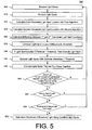
- FIG. 5 shows a flowchart illustrating one embodiment of a method 500 of determining a wavefront of a received light beam by qualifying which light spot data is employed for wavefront the measurements.
- method 500 may be performed by a system such as the system 1000 which will be described in greater detail below with respect to FIG. 15 .
- a wavefront sensor receives a light beam.
- the light beam is received back from the retina of a subject's eye.
- a lenslet array of the wavefront sensor produces a group of light spots from the received light beam and images those light spots onto a detector array.
- a processor calculates a first calculated location of each light spot in the group of light spots using a first calculation algorithm.
- a first calculation algorithm An exemplary embodiment of such a first calculation algorithm will be described below with respect to FIGs. 6A-D .
- a processor calculates a second calculated location of each light spot in the group of light spots using a second calculation algorithm that is different from the first calculation algorithm.
- a second calculation algorithm that is different from the first calculation algorithm.
- the processor calculates a difference between the first and second calculated locations for each light spot in the group.
- a step 535 for each light spot in the group, the processor compares the difference between the first and second calculated locations for the light spot, to a predetermined agreement threshold.
- the processor excludes from a qualified set of light spots those light spots where the difference between the first and second calculated locations is greater than the agreement threshold.
- the qualified set of spots can be employed in determining the wavefront of the received light beam
- a step 545 the processor determines a summed intensity value of an assigned group of pixels of the detector array assigned to each light spot, and excludes from the set of qualified light spots those light spots whose summed intensity is less than a predetermined summed intensity threshold. Absolute intensity thresholds which are tested in step 545 insure that light spots are sufficiently bright to yield accurate data. An exemplary embodiment of such algorithm for performing step 545 will be described below with respect to FIG. 12 .
- a step 550 the remaining light spots in the qualified set of light spots are checked to insure that each light spot belongs to only one predetermined area of interest (AOI) in the detector array.
- the distance between adjacent light spot locations is compared to a minimum distance threshold. In that case if the distance between the adjacent light spot locations is less than the distance threshold, then one or both light spots are excluded from the set of qualified light spots.
- a step 555 an algorithm is employed to insure that the received light beam has not been deleteriously affected by phenomena such as a subject blinking their eye during the measurements, an eyelash blocking part of the light path, etc.
- qualified light spot data is passed to a pupil analysis algorithm to locate the pupil and define its shape and guard against partial blinks.
- a pupil analysis algorithm to locate the pupil and define its shape and guard against partial blinks.
- the processor determines the size of the largest cluster of connected or adjacent "missing" light spots in the image produced by the lenslet array on the detector array (see missing light spots 330 in FIG. 3 ) and compares it to a predetermined cluster size threshold (e.g., 21 connected light spots). If the number of connected or adjacent missing light spots is greater than the cluster size threshold, then the entire set of wavefront data is discarded and the process returns to step 510.
- a predetermined cluster size threshold e.g. 21 connected light spots
- N lenslets in the lenslet array that are illuminated by the light beam from the subject's pupil
- N light spots in the set of qualified light spots may be missing, or may be disqualified from the set of qualified light spots based on the criteria applied in one or more of the steps above.
- the processor determines the number or percentage of light spots that are missing or disqualified from the set of qualified light spots, and compares the number or percentage to a missing light spot threshold (e.g., 20%). If the percentage exceeds the threshold, then the entire set of wavefront data is discarded and the process returns to step 510.
- a missing light spot threshold e.g. 20%
- the number of qualified spots within the pupil, the percent fraction of qualified spots within the pupil, and the number of connected disqualified spots may be tallied and compared to the predetermined threshold criteria to qualify the frame of data for wavefront analysis.
- the wavefront measurement instrument determines the wavefront of the received light beam using the qualified set of light spots.
- all missing or disqualified data within the pupil may be interpolated from the qualified light spots.
- the qualified light spots are used to determine the local gradients at those respective points. These slope values and positions are used in a Zernike wavefront fit. The coefficients are used to generate slope data at the missing light points.
- method 500 employs two different methods to determine light spot locations and performs a spot by spot cross check on the light spot locations using two or more different light spot location determination methods.
- a variety of different methods may be employed for determining the locations of the light spots.
- intensity-based methods may be employed to determine which pixels to include in the light spot location calculation.
- spatially-based methods may use a priori information about what constitutes a "normal" light spot to determine which pixels to include in the light spot location calculation.
- correlation based methods are employed using correlation values to determine which pixels to include in the light spot location calculation.
- both methods calculate the first moments of the light spot minus the background intensity, however the pixels used in the calculations and the background intensity values are determined differently for each method.
- the selected methods exhibit a high degree of agreement for typical light spot distributions; however they disagree for light spots with pathological distributions.
- light spots are disqualified whenever the locations from the two methods differ by more than a predetermined agreement threshold.
- the agreement threshold is set to one pixel.
- the method 500 may be modified to exclude certain of the steps shown in FIG. 5 .
- the method 500 may be modified to exclude one or more of the exclusion criteria steps 535, 540, 545, and/or 550. Additionally or alternatively, one or more of the steps 555, 560, or 565 may be excluded from the method 500.
- the method 500 may include additional steps. For example, in addition to, or in place of one of more of the frame qualification tests performed in steps 555-565, an
- the qualified spots may be assigned a weighting depending on an evaluation criteria (e.g., amount above or below one of the thresholds used in the method 500, or distance from a nearest neighbor).
- some or all of the light spots excluded from the set of qualified light spots may be further evaluated or processed.
- some or all of the excluded light spots may be evaluated for inclusion in a second set of light spots.
- the step 570 of method 500 may include the second set of light spots in determining the wavefront, for example, by assigning a reduced weight in calculating the wavefront as compared to the weight or weights given to spots in the qualified set.
- the second set of light spots may be used to detect a condition of the optical system or eye (e.g., a cataract condition) and/or form the basis of a qualitative or quantitative characterization of the mechanisms that caused the disqualification.
- a condition of the optical system or eye e.g., a cataract condition
- the location and severity of local phase and intensity perturbations caused by cataracts and/or large corneal surface deviation may be measured or estimated based on the second set of light spots.
- the method 500 may be adapted or modified for use with other types of input data and/or for making other types of calculations.
- the light spots may be produced by a corneal topographer, where light reflected from a cornea or other surface are imaged onto a detector to produce a set of light spots that are indicative of a local slope of the cornea or surface.
- the light spots may be processed using the steps and criteria shown in FIG. 5 and/or using other criteria suitable for evaluating or processing data from gradient measurements located on relatively non-rectangular grids, for example, as disclosed in co-pending US patent application numbers 12/347,909 and 12/350,895 .
- steps 540, 545 and 550 can be changed; one or more of steps 540, 545 and 550 could be performed before steps 515-535; the order of steps 555 and 560 can be changed; one or more of steps 555 and 560 could be performed before steps 515-535 and/or steps 540, 545 and/or 550; etc.
- FIGs. 6A-D illustrate one embodiment of a first method of locating a light spot in a method such as method 500 illustrated in FIG. 5 .
- the method illustrated in FIGs. 6A-D is hereinafter referred to as the "Percent Threshold Method.”
- the Percent Threshold Method incorporates two parameters: an Irradiance Threshold 610 and a Percent Threshold 620.
- the Irradiance Threshold 610 is used to eliminate camera noise and stray light from the data used in the light spot centroid location calculation and is assumed to be constant across the image.
- the Irradiance Threshold 610 is nominally set at a value of 30 counts from those pixels of the detector array assigned to each light spot (i.e., the "Area of Interest" or AOI).
- the Percent Threshold 620 is used to dynamically threshold the intensity data in proportion to the valid data brightness within the AOI to afford a wide variance in the spot brightness. This is in effect a local threshold that depends on the spot brightness that is crucial for use in instruments where a large variance is in spot brightness or size can be expected; e.g., ophthalmic aberrometers and laser metrology tools. It is generally quite robust against spot brightness but assumes a constant background level, the Irradiance Threshold 610.
- the raw intensity values of the pixels within a given AOI are thresholded with a value equal to the Irradiance Threshold 610 plus the product of the Percent Threshold 620 times the brightest intensity minus the Irradiance Threshold 610.
- the x and y first moments of the pixel data within the AOI are then calculated, as is the sum of the valid intensity, i.e., the sum of the raw intensity values minus the Irradiance Threshold.
- FIGS. 6A-B illustrate a well-formed light spot
- FIGS. 6C-D show a light spot just to the right of the corneal reflex.
- FIGs. 6A and 6C show the intensity of the light impinging on the pixels arranged in the x and y directions within the AOI. The pixels in the outlined areas are included in the first moment's calculation.
- FIGs. 6b and 6D show the intensity distribution in the x direction for determining the x component of the first moment of of the intensity distribution within the AOI.
- a first method of locating a light spot comprises: assigning a group of the pixels to the light spot; establishing a pixel intensity threshold for the light spot; determining an intensity value for light received at each pixel in the group; and calculating the first calculated location as a first moment of the pixel intensity values for those pixels whose intensity values are greater than the pixel intensity threshold.
- the pixel intensity threshold for the light spot is established by: establishing a background intensity threshold value that is constant for all light spots; determining a maximum intensity value among the intensity values for all of the pixels in the group; establishing a percentage threshold value for the light spot; and establishing the pixel intensity threshold by multiplying the percentage threshold value by the maximum intensity value and subtracting the background intensity threshold value.
- FIGs. 7A-D illustrate one embodiment of a second method of locating a light spot in a wavefront sensor.
- the method illustrated in FIGs. 7A-D is hereinafter referred to as the "Window Method.”
- the Window Method uses a priori information about the light spot dimensions and the location of the brightest pixel within the AOI to determine which pixels to use in the first moment's calculations, and what background value of light to subtract.
- the Window Method uses a spatial criteria and a local background value.
- window 710 is a square whose size is sufficiently large to enclose only the primary lobe of the light spot pattern, but considerably smaller than the AOI.
- the size of the window 710 is set to nine (9) pixels in each direction.
- the brightest pixel in the AOI is located within one half of the window's length from the edge of the AOI, then the window is truncated at the edge of the AOI. Only pixels within window 710 are used to determine the light spot's location. The intensity values of the pixels along the border of the window are reviewed and the brightest value is used to threshold the intensity of the pixels within window 710. Then the x and y first moments and the sum of the thresholded intensity values for pixels in window 710 are calculated.
- the Window Method returns a light spot location and intensity of zero whenever the intensity of a pixel on the border of window 710 is equal to the intensity of the brightest pixel in the AOI. This routinely occurs in and around the corneal reflex.
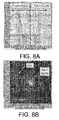
- FIGs. 8A-B illustrate differences in the locations of light spots determined by the method of FIGs. 6A-D and locations determined by the method of FIGs. 7A-D for an exemplary image.
- FIG. 8A shows an exemplary histogram plot of the differences between the calculated locations of the light spots using the Percent Threshold Method and the calculated locations of the light spots using the Window Method, in pixels, for a bin size equal to 0.01 pixels
- FIG. 8B shows the differences for each light spot.
- the differences for the AOIs that have many fully saturated pixels are of order 100's of pixels and are not shown in FIGs. 8A-B .
- the Percent Threshold Method and the Window Method produce light spot locations that agree with each other to within a small fraction of a pixel.
- the light spots are asymmetric, significantly broader than the size of the window employed in the Window Method, reside on a non-uniform or strong background, or are strongly saturated, such as near the corneal reflex, these methods will report spot locations that differ.
- the differences are typically quite small for well formed light spots, and quite large for pathological light spots.
- the difference is typically less than 0.1 pixels and for poorly formed light spots it is typically well above one pixel.
- the agreement threshold value is set to 1 pixel, so as to discriminate between well formed light spots and pathological light spots. In that case, light spots whose calculated locations using the Percent Threshold Method and the Window Method disagree by more than the agreement threshold are then disqualified or excluded from being employed in the wavefront calculations.
- FIGS. 9-11 illustrate examples of various error cases.
- FIG. 9 shows a raw image from a wavefront sensor for a subject with an intraocular lens.
- An IOL patient shows multiple corneal reflexes. Light spots affected by these multiple corneal reflexes may be disqualified or excluded from being employed in the wavefront measurements by calculating their locations through two different location calculation algorithms and comparing the differences in the locations obtained by the two algorithms to an agreement threshold, as explained in examples above.
- FIG. 10 shows a raw image from a wavefront sensor for a subject with cataracts. Images from cataract patients often contain focal spots that are quite broad and dim because of the scattering in the lens. Again, these dim or misshapen light spots may be disqualified or excluded from being employed in the wavefront measurements by calculating their locations through two different location calculation algorithms and comparing the differences in the locations obtained by the two algorithms to an agreement threshold, as explained in examples above.
- FIG. 11 shows a raw image from a wavefront sensor for a subject with a weak corneal reflex. Light spots affected by even this weak corneal reflex may be disqualified or excluded from being employed in the wavefront measurements by calculating their locations through two different location calculation algorithms and comparing the differences in the locations obtained by the two algorithms to an agreement threshold, as explained in examples above.
- light spots were also screened according to their summed intensity.
- light spots whose summed intensities are less than a predetermined summed intensity threshold may be disqualified or excluded from being employed in the wavefront measurements.
- FIG. 12 is a histogram illustrating the summed intensity of pixels in a light spot as a function of occurrence for an exemplary image. From this data it is suggestive that a minimum summed intensity of around 30 counts will reject only about 2% of the light spots, most of which are from partially illuminated lenslets on the pupil boundary. Accordingly, in one embodiment the summed intensity threshold is set to 30.
- FIGs. 13A-B illustrate embodiments of two methods for determining the location and shape of a subject's pupil.
- An embodiment of a first pupil location determination method is based on a center of mass algorithm.
- An embodiment of a second pupil location determination method is based on a Convex Hull algorithm, using a priori knowledge that the boundary shape of the pupil should be generally circular, and mapping the light spots to match the expected boundary shape - where perhaps a portion of the pupil has been blocked or obscured.
- the pupil center and diameter are calculated using on the same light spot data using the two different methods.
- the data in FIGs. 13A-B show a case where the patient's eyelashes and/or eyelid partially obscure the wavefront data.
- the center of mass method is illustrated in FIG.
- FIG. 13A leads to erroneous pupil center and diameter in this example.
- the Convex Hull algorithm illustrated in FIG. 13B minimizes the effects of eyelashes and blinking compared to center of mass algorithm.
- FIGs. 13A-B the cross and circle represent the results of each method.
- a pupil location agreement threshold is set to 200 ⁇ m. In that case, the center of the pupil as calculated by both methods should agree to within 200 ⁇ m in order for the frame of data to be considered valid for wavefront measurement. Otherwise, the entire set of light spot data is discarded and a new image is employed for the wavefront measurement.
- one of the two methods of determining the location and shape of the pupil may instead employ an image captured by an iris camera (e.g. iris camera 460 in FIG. 4 ) instead of the light spot data from the wavefront sensor.
- an iris camera e.g. iris camera 460 in FIG. 4
- FIGs. 14A-B are plots illustrating the correlation of exemplary measurements made by the two Convex Hull and center of mass methods.
- FIG. 15 shows one embodiment of a system 1000 for measuring aberrations and the corneal topography of an eye 10.
- System 1000 comprises a structure 1100 having a principal surface 1120 with an opening or aperture 1140 therein; a plurality of first (or peripheral) light sources 1200 provided on the principal surface 1120 of the structure 1100; a plurality of second, or central, light sources 1300 (also sometimes referred to as "Helmholtz light sources”); a detector array 1400; a processor 1410; a third light source 1500 providing a probe beam; a wavefront sensor 1550; and an optical system 1700 disposed along a central axis 1002 passing through the opening or aperture 1140 of the structure 1100.
- Optical system 1700 comprises a quarterwave plate 1710, a first beamsplitter 1720, a second beamsplitter 1730, an optical element (e.g., a lens) 1740, a third beamsplitter 1760, and a structure including an aperture 1780.
- third light source 1500 includes a lamp 1520, a collimating lens 1540, and light source polarizing beamsplitter 1560.
- a wavefront analysis system 1600 also comprising: a polarizing beamsplitter 1620; an adjustable telescope 1640 comprising a first optical element (e.g., lens) 1642 and a second optical element (e.g., lens) 1644 and a movable stage or platform 1646; and a dynamic-range limiting aperture 1650 for limiting a dynamic range of light provided to wavefront sensor 1550.
- a polarizing beamsplitter 1620 comprising a first optical element (e.g., lens) 1642 and a second optical element (e.g., lens) 1644 and a movable stage or platform 1646
- a dynamic-range limiting aperture 1650 for limiting a dynamic range of light provided to wavefront sensor 1550.
- system 1000 further comprises a fixation target system 1800, comprising light source 1820 and lenses 1840, 1860, and 1880.
- the operation of the topographer portion of system 1000 may be illustrated based on the combined use of first and second light sources 1200, 1300.
- the images of first light sources 1200 that appear on detector array 1400 emanate from an outer region of the surface of the cornea
- the images of second light sources 1300 that appear on detector array 1400 emanate from a central or paraxial region of the surface of the cornea. Accordingly, even though information about the central region of the corneal surface (e.g., surface curvature) cannot be determined from the images of first light sources 1200 on detector array 1400, such information can be determined from the images of second light sources 1300 on detector array 1400.
- Detector array 1400 detects the light spots projected thereon from both second light sources 1300 (detected at a central portion of detector array 1400) and first light sources 1200 (detected at a peripheral portion of detector array 1400) and provides corresponding output signals to processor 1410.
- Processor 1410 determines the locations and/or shapes of the light spots on detector array 1400, and compares these locations and/or shapes to those expected based for a standard or model cornea, thereby allowing processor 1410 to determine the corneal topography of eye 100. Accordingly, the topography of the entire corneal surface can be characterized by system 1000 without a "hole" or missing data from the central corneal region.
- Data from the wavefront sensor 1550 may be analyzed using the method 500 described above.
- FIG. 16 shows a flowchart illustrating one embodiment of a method 2000 of qualifying light spot data for a corneal topography measurement by an instrument such as corneal topographer portion of the system 1000 of FIG. 15 .
- the method 2000 may be adapted, and modified as appropriate, to analyze data for other topographer systems used to measure the topography of a cornea or the surface profile of some other test object, such as a test mirror or lens.
- a plurality of light sources is provided.
- a test object e.g., the cornea of the eye 10 for the system 1000
- a test object is illuminated with light from the plurality of light sources.
- step 2015 light that has illuminated the test object is provided to an optical system.
- a group of light spots corresponding to the light sources are produced on a detector array.
- a processor calculates a first calculated location of each light spot using a first calculation algorithm.
- a processor calculates a second calculated location of each light spot using a second calculation algorithm different from the first calculation algorithm.
- the processor calculates a difference between the first and second calculated locations.
- the processor compares the difference between the first and second calculated locations for the light spot, to a predetermined agreement threshold.
- the processor excludes from a qualified set of light spots those light spots where the difference between the first and second calculated locations is greater than the agreement threshold.
- the qualified set of spots is employed in determining a property of the eye 100, for example, a surface shape of the cornea of the eye 1.0.
- a property of the test object is determined using the qualified set of light spots.
- the method 2000 may include additional steps. For example, for the purposes of determining the property of the test object, the qualified spots may be assigned a weighting depending on an evaluation criteria. Additionally or alternatively, some or all of the light spots excluded from the set of qualified light spots may be further evaluated or processed. For example, some or all of the excluded light spots may be evaluated for inclusion in a second set of light spots. In such embodiments, the step 2050 of method 2000 may include the second set of light spots in determining the property of the test object, for example, by assigning a reduced weight in calculating the wavefront as compared to the weight or weights given to spots in the qualified set.
- the second set of light spots may be used to detect a condition of the test object (e.g., a cataract or dry eye condition or chronic dry eye condition when the test object is the eye 10) and/or from the basis of a qualitative or quantitative characterization of the mechanisms that caused the disqualification.
- a condition of the test object e.g., a cataract or dry eye condition or chronic dry eye condition when the test object is the eye
- the location, severity, and/or extent of tear film breakup may be measured or estimated based on the second set of light spots.
- the location and severity of larger local surface anomalies of a cornea surface caused by large corneal surface deviation may be measured or estimated based on the second set of light spots.
- data from both the wavefront sensor 1550 of system 1000 and the topographer portion of system 1000 may be used together to qualify data from one system and/or the other.
- FIG. 17 shows an exemplary topographic image of an eye produced from the corneal topographer portion of system 1000.
- FIG. 18 shows exemplary wavefront data of the same eye from wavefront sensor 1550 of system 1000, superimposed on top of the topographic image of FIG. 17 .
- the data from both the wavefront sensor and topographer is generally well behaved and both may be used to provide validated measurements of the eye.
- FIG. 19 shows another exemplary topographic image of the same eye using the system 1000 is shown, where the blurred spot images in the bottom portion of the image give clear indication of the presences, severity, and extent of the tear film breakup due to a dry eye or chronic dry eye condition.
- FIG. 20 shows exemplary wavefront data from the wavefront sensor 1550 that is superimposed on top of the topographer image of FIG. 19 for the same eye under the same conditions. In this case, the wavefront data is still fairly well behaved, with only a few data points (dark squares within the generally circular wavefront data image) being disqualified. However, based on the topographic image in FIG. 19 , all or portions of the wavefront data shown in FIG. 20 may be disqualified based on the tear film breakup indicated from the topographer data shown in FIG. 19 . Thus, the image from a corneal topography measurement may be used to modify or eliminate data provided by the wavefront sensor alone.
- FIG. 21 is another illustration of exemplary wavefront data from the wavefront sensor 1550 that is superimposed on top of a topographic image for an eye taken under the same conditions (e.g., at the same time).
- FIG. 21 illustrates an opposite case to that explained above with respect to FIGs. 19 and 20 .
- the corneal topography image appears to be normal, but the wavefront data is mottled.
- the wavefront data may be used to modify or eliminate data provided by the corneal topographer alone.
- FIG. 22 shows data from the wavefront sensor 1550 for a condition in which the light spots in one region of the eye have relatively large deviations from a nominal condition.
- This anomalous region of the eye is indicated by the square in the overall light spot image shown on the left side of FIG. 22 .
- a magnified view of this region is shown in the box on the right side of FIG. 22 .
- the nominal light spot positions are indicated by the lined grid in the magnified view.
- many of the light spots within the enclosed area have visibly large deviations compared to the other light spots outside the enclosed area.
- the topography light spot for the same region of the eye showed relatively small deviations that were within expected nominal values for a typical cornea.
- the source of the large deviations in FIG. 22 had to come from abnormality within the eye, for example due to the presence of a cataract within the natural lens.
- a comparison of the wavefront data in FIG. 22 with the corresponding topographer data may be used to detect or determine an abnormality of the eye, such as the presence of a cataract.
- FIG. 23 shows a flowchart illustrating one embodiment of a method 2300 of performing a wavefront measurement and a corneal topography measurement of an eye.
- method 2300 may be performed by a system such as the system 1000 illustrated in FIG. 15 .
- a first set of light spots are obtained from a wavefront aberrometer such as the wavefront aberrometer of the system 1000 of FIG. 15 .
- step 2305 may include steps 505-510 of method 500 described above.
- the first light spots comprising wavefront data may be qualified to produce a first qualified set of light spots.
- step 2310 may include steps 515-540 of method 500 described above.
- a second set of light spots are obtained from a corneal topographer instrument such as corneal topographer portion of the system 1000 of FIG. 15 .
- step 2305 may include steps 2005-2020 of method 2000 described above.
- step 2315 is performed at a same time as step 2305. That is, beneficially the corneal topography image of an eye produced by step 2315 is taken at the same time that the wavefront data for the same eye is produced by step 2305.
- the second light spots may be qualified to produce a second qualified set of light spots.
- step 2310 may include steps 2025-2045 of method 2000 described above. In one embodiment, step 2310 may include steps 2025-2045 of method 2000 described above.
- the first light spots from the wavefront aberrometry measurement are qualified by the image formed by the second light spots produced by the corneal topography measurement.
- the first light spots and/or the second light spots employed in step 2325 maybe qualified by step 2310 and/or step 2320 as described above.
- An example of qualifying the wavefront light spots by a corneal topography image is described above with respect to FIGs. 17-20 .
- the second light spots from the corneal topography measurement are qualified by the image formed by the first light spots produced by the wavefront aberrometry measurement.
- the first light spots and/or the second light spots employed in step 2330 may be qualified by step 2310 and/or step 2320 as described above.
- An example of qualifying the topography light spots by wavefront data is described above with respect to FIG 21 .
- a clinical study was performed using a system similar to the system 100 - a system containing both a wavefront aberrometer and corneal topographer.
- the study specifically looked at wavefront aberrometer and topography data for measuring astigmatism in a population of subject eyes. Based on wavefront aberrometer and topography data from the population, the inventors made various observations. Corneal and wavefront aberrations are weakly correlated for the entire population. For eyes with manifest refraction less than 1D there is no correlation between corneal and total wavefront aberration. For eyes with manifest astigmatism greater than 1D, the correlation is stronger and about 80% of the aberration can be attributed to the cornea. By examining combined corneal and wavefront data the source of wavefront aberration can be attributed to the cornea or other ocular components.
Landscapes
- Health & Medical Sciences (AREA)
- Life Sciences & Earth Sciences (AREA)
- Physics & Mathematics (AREA)
- Engineering & Computer Science (AREA)
- Surgery (AREA)
- Public Health (AREA)
- Biomedical Technology (AREA)
- Heart & Thoracic Surgery (AREA)
- Medical Informatics (AREA)
- Molecular Biology (AREA)
- Biophysics (AREA)
- Animal Behavior & Ethology (AREA)
- General Health & Medical Sciences (AREA)
- Ophthalmology & Optometry (AREA)
- Veterinary Medicine (AREA)
- General Physics & Mathematics (AREA)
- Computer Vision & Pattern Recognition (AREA)
- Geometry (AREA)
- Chemical & Material Sciences (AREA)
- Analytical Chemistry (AREA)
- Eye Examination Apparatus (AREA)
- Photometry And Measurement Of Optical Pulse Characteristics (AREA)
Claims (15)
- Procédé d'utilisation d'un capteur optique pour déterminer une propriété d'un objet, le procédé comprenant :(a) l'illumination de l'objet par une lumière provenant d'une ou plusieurs sources de lumière ;(b) la réception de lumière en provenance de l'objet illuminé ;(c) la production d'un groupe de taches lumineuses à partir de la lumière reçue ;(d) la qualification d'un ensemble des taches lumineuses à utiliser dans la détermination d'une propriété de l'objet ; et(e) la détermination de la propriété de l'objet en utilisant l'ensemble qualifié de taches lumineuses,dans lequel la qualification de l'ensemble de taches lumineuses inclut, pour chaque tache lumineuse dans le groupe de taches lumineuses :le calcul d'un premier emplacement calculé de la tache lumineuse en utilisant un premier algorithme de calcul ;le calcul d'un second emplacement calculé de la tache lumineuse en utilisant un second algorithme de calcul différent du premier algorithme de calcul ; etquand une différence entre les premier et second emplacements calculés pour la tache lumineuse est plus grande qu'un seuil d'agrément, l'exclusion de la tache lumineuse de l'ensemble qualifié de taches lumineuses.
- Procédé selon la revendication 1, dans lequel le capteur optique inclut un groupement de détecteurs ayant une pluralité de pixels, et dans lequel la qualification de l'ensemble de taches lumineuses comprend en outre, pour chaque tache lumineuse non déjà exclue de l'ensemble qualifié de taches lumineuses, la détermination d'une valeur d'intensité sommée d'un groupe attribué de pixels du groupement de détecteurs attribué à la tache lumineuse et l'exclusion hors de l'ensemble qualifié de taches lumineuses de n'importe quelle tache lumineuse dont l'intensité sommée est inférieure à un seuil d'intensité sommée.
- Procédé selon la revendication 1, dans lequel le capteur optique inclut un capteur de front d'onde et la qualification de l'ensemble de taches lumineuses comprend en outre :la détermination d'une différence entre un premier emplacement déterminé d'une pupille d'un oeil comme on le détermine à partir d'un front d'onde détecté selon un premier procédé, et un second emplacement déterminé de la pupille déterminé à partir d'un second procédé différent du premier procédé ; etquand une différence entre le premier emplacement déterminé et le second emplacement déterminé est supérieure à un seuil d'agrément d'emplacement de pupille, alors l'exclusion de la totalité des taches lumineuses dans le groupe de taches lumineuses et la répétition des étapes (a) à (d) pour un nouveau groupe de taches lumineuses avant l'exécution de l'étape (e).
- Procédé selon la revendication 1, dans lequel la qualification de l'ensemble de taches lumineuses comprend en outre :la détermination d'une taille d'un agrégat le plus grand de taches lumineuses qui ont été exclues jusqu'ici de l'ensemble qualifié de taches lumineuses ; etlorsque la taille d'un agrégat le plus grand de taches lumineuses qui ont été exclues de l'ensemble qualifié de taches lumineuses est jusqu'ici plus grande qu'un seuil de taille d'agrégat, alors l'exclusion de la totalité des taches lumineuses dans le groupe de taches lumineuses et la répétition des étapes (a) à (d) pour un nouveau groupe de taches lumineuses avant l'exécution de l'étape (e).
- Procédé selon la revendication 1, dans lequel le capteur optique inclut un groupement de détecteurs ayant une pluralité de pixels, et dans lequel le calcul du premier emplacement calculé pour chaque tache lumineuse en utilisant le premier algorithme de calcul comprend, pour chaque tache lumineuse :l'attribution d'un groupe des pixels à la tache lumineuse ;l'établissement d'un seuil d'intensité de pixel pour la tache lumineuse ;la détermination d'une valeur d'intensité pour la lumière reçue au niveau de chaque pixel dans le groupe ; etle calcul du premier emplacement calculé en tant que premier moment des valeurs d'intensité de pixel pour ces pixels dont les valeurs d'intensité sont plus grandes que le seuil d'intensité de pixel.
- Procédé selon la revendication 1, dans lequel le capteur optique inclut un groupement de détecteurs ayant une pluralité de pixels, et dans lequel le calcul du second emplacement calculé pour chaque tache lumineuse en utilisant le second algorithme de calcul comprend :l'attribution d'un groupe des pixels à la tache lumineuse ;la détermination d'une valeur d'intensité pour la lumière reçue au niveau de chaque pixel dans le groupe ;la détermination d'un pixel le plus lumineux ayant une valeur d'intensité maximale parmi les valeurs d'intensité pour la lumière reçue au niveau de la totalité des pixels dans le groupe ;l'établissement d'une fenêtre spatiale entourant le pixel le plus lumineux ;le paramétrage d'un seuil de fenêtre égal à la valeur d'intensité maximale parmi les valeurs d'intensité pour des pixels situés sur une frontière de la fenêtre spatiale ; etle calcul du second emplacement calculé en tant que premier moment des valeurs d'intensité de pixel pour ces pixels dont les valeurs d'intensité sont plus grandes que le seuil de fenêtre.
- Dispositif comprenant :une ou plusieurs sources de lumière pour illuminer un objet ;un générateur de tache lumineuse conçu pour recevoir de la lumière en provenance de l'objet illuminé et pour produire un groupe de taches lumineuses à partir de la lumière reçue en provenance de l'objet illuminé ;un détecteur conçu pour détecter les taches lumineuses et pour sortir des données de tache lumineuse se rapportant à chaque tache lumineuse ; etun processeur conçu pour traiter les données de tache lumineuse pour déterminer une propriété de l'objet par :la qualification d'un ensemble des taches lumineuses à utiliser dans la détermination de la propriété, etla détermination de la propriété de l'objet en utilisant l'ensemble qualifié de taches lumineuses,dans lequel la qualification de l'ensemble de taches lumineuses inclut, pour chaque tache lumineuse dans le groupe de taches lumineuses :le calcul d'un premier emplacement calculé de la tache lumineuse à partir des données de tache lumineuse en utilisant un premier algorithme de calcul ;le calcul d'un second emplacement calculé de la tache lumineuse à partir des données de tache lumineuse en utilisant un second algorithme de calcul différent du premier algorithme de calcul ; etquand une différence entre les premier et second emplacements calculés pour la tache lumineuse est plus grande qu'un seuil d'agrément, l'exclusion de la tache lumineuse hors de l'ensemble qualifié de taches lumineuses.
- Dispositif selon la revendication 7, dans lequel la qualification de l'ensemble de taches lumineuses comprend en outre, pour chaque tache lumineuse non déjà exclue de l'ensemble de taches lumineuses, la détermination d'une intensité sommée de la tache lumineuse à partir des données de tache lumineuse et en excluant de l'ensemble de taches lumineuses n'importe quelle tache lumineuse dont l'intensité sommée est inférieure à un seuil d'intensité sommée.
- Dispositif selon la revendication 8, dans lequel le détecteur comprend un groupement de pixels, et dans lequel la détermination de l'intensité sommée d'une tache lumineuse comprend :l'attribution d'un groupe des pixels à la tache lumineuse ;la détermination d'une valeur d'intensité pour la lumière reçue au niveau de chaque pixel dans le groupe à partir des données de tache lumineuse ; etl'addition des valeurs d'intensité de pixel pour déterminer l'intensité sommée de la tache lumineuse.
- Dispositif selon la revendication 7, dans lequel le dispositif inclut un capteur de front d'onde, et dans lequel la qualification de l'ensemble de taches lumineuses comprend en outre :la détermination d'une différence entre un premier emplacement déterminé d'une pupille d'un oeil comme on le détermine à partir d'un front d'onde détecté selon un premier procédé, et un second emplacement déterminé de la pupille déterminé à partir d'un second procédé différent du premier procédé ; etlorsque la différence entre le premier emplacement déterminé et le second emplacement déterminé est plus grande qu'un seuil d'agrément d'emplacement de pupille, alors l'exclusion de la totalité des taches lumineuses dans le groupe de taches lumineuses, l'obtention de nouvelles données de tache lumineuse à partir d'un nouveau groupe de taches lumineuses, et le traitement des nouvelles données de tache lumineuse.
- Dispositif selon la revendication 7, dans lequel la qualification de l'ensemble de taches lumineuses comprend en outre :la détermination d'une taille d'un agrégat le plus grand de taches lumineuses qui ont été exclues jusqu'ici de l'ensemble qualifié de taches lumineuses ; etlorsque la taille d'un agrégat le plus grand de taches lumineuses qui ont été exclues jusqu'ici de l'ensemble qualifié de taches lumineuses est plus grande qu'un seuil de taille d'agrégat, alors l'exclusion de la totalité des taches lumineuses dans le groupe de taches lumineuses, l'obtention de nouvelles données de tache lumineuse à partir d'un nouveau groupe de taches lumineuses, et le traitement des nouvelles données de tache lumineuse.
- Dispositif selon la revendication 7, dans lequel le détecteur comprend un groupement de pixels, et dans lequel le calcul du premier emplacement calculé pour chaque tache lumineuse en utilisant le premier algorithme de calcul comprend :l'attribution d'un groupe des pixels à la tache lumineuse ;l'établissement d'un seuil d'intensité de pixel pour la tache lumineuse ;la détermination d'une valeur d'intensité pour la lumière reçue au niveau de chaque pixel dans le groupe ; etle calcul du premier emplacement calculé en tant que premier moment des valeurs d'intensité de pixel pour ces pixels dont les valeurs d'intensité sont plus grandes que le seuil d'intensité de pixel.
- Dispositif selon la revendication 12 ou procédé selon la revendication 5, dans lequel l'établissement du seuil d'intensité de pixel pour la tache lumineuse comprend :l'établissement d'une valeur de seuil d'intensité de fond qui est constante pour toutes les taches lumineuses ;la détermination d'une valeur d'intensité maximale parmi les valeurs d'intensité pour la totalité des pixels dans le groupe ;l'établissement d'une valeur de seuil de pourcentage pour la tache lumineuse ; etl'établissement du seuil d'intensité de pixel en multipliant la valeur de seuil de pourcentage par la valeur d'intensité maximale et la soustraction de la valeur de seuil d'intensité de fond.
- Dispositif selon la revendication 12 ou procédé selon la revendication 5, dans lequel le calcul du second emplacement calculé pour chaque tache lumineuse en utilisant le second algorithme de calcul comprend :la détermination d'un pixel le plus lumineux ayant une valeur d'intensité maximale parmi les valeurs d'intensité pour la lumière reçue au niveau de tous les pixels dans le groupe ;l'établissement d'une fenêtre spatiale entourant le pixel le plus lumineux ;la fixation d'un seuil de fenêtre égal à la valeur d'intensité maximale parmi les valeurs d'intensité pour des pixels situés sur une frontière de la fenêtre spatiale ; etle calcul du second emplacement calculé en tant que premier moment des valeurs d'intensité de pixel pour ces pixels dont les valeurs d'intensité sont plus grandes que le seuil de fenêtre.
- Dispositif selon la revendication 7, dans lequel le détecteur comprend un groupement de pixels, et dans lequel le calcul du second emplacement calculé pour chaque tache lumineuse en utilisant le second algorithme de calcul comprend :l'attribution d'un groupe des pixels à la tache lumineuse ;la détermination d'une valeur d'intensité pour la lumière reçue au niveau de chaque pixel dans le groupe ;la détermination d'un pixel le plus lumineux ayant une valeur d'intensité maximale parmi les valeurs d'intensité pour la lumière reçue au niveau de la totalité des pixels dans le groupe ;l'établissement d'une fenêtre spatiale entourant le pixel le plus lumineux ;la fixation d'un seuil de fenêtre égal à la valeur d'intensité maximale parmi les valeurs d'intensité pour des pixels situés sur une frontière de la fenêtre spatiale ; etle calcul du second emplacement calculé en tant que premier moment des valeurs d'intensité de pixel pour ces pixels dont les valeurs d'intensité sont plus grandes que le seuil de fenêtre.
Applications Claiming Priority (6)
| Application Number | Priority Date | Filing Date | Title |
|---|---|---|---|
| US11497808P | 2008-11-14 | 2008-11-14 | |
| US15749609P | 2009-03-04 | 2009-03-04 | |
| US15749709P | 2009-03-04 | 2009-03-04 | |
| US16385809P | 2009-03-25 | 2009-03-25 | |
| US12/607,368 US7988293B2 (en) | 2008-11-14 | 2009-10-28 | Method of qualifying light spots for optical measurements and measurement instrument employing method of qualifying light spots |
| PCT/US2009/064390 WO2010056997A2 (fr) | 2008-11-14 | 2009-11-13 | Procédé de qualification de taches lumineuses pour des mesures optiques et instrument de mesure employant le procédé de qualification de taches lumineuses |
Publications (2)
| Publication Number | Publication Date |
|---|---|
| EP2364429A2 EP2364429A2 (fr) | 2011-09-14 |
| EP2364429B1 true EP2364429B1 (fr) | 2013-03-13 |
Family
ID=42061152
Family Applications (1)
| Application Number | Title | Priority Date | Filing Date |
|---|---|---|---|
| EP09752695A Not-in-force EP2364429B1 (fr) | 2008-11-14 | 2009-11-13 | Procédé de qualification de taches lumineuses pour des mesures optiques et instrument de mesure employant le procédé de qualification de taches lumineuses |
Country Status (5)
| Country | Link |
|---|---|
| US (1) | US7988293B2 (fr) |
| EP (1) | EP2364429B1 (fr) |
| AU (4) | AU2009313918B2 (fr) |
| CA (3) | CA3017003C (fr) |
| WO (1) | WO2010056997A2 (fr) |
Cited By (2)
| Publication number | Priority date | Publication date | Assignee | Title |
|---|---|---|---|---|
| WO2017113146A1 (fr) * | 2015-12-28 | 2017-07-06 | 苏州中启维盛机器人科技有限公司 | Dispositif d'imagerie à moucheture |
| US10582852B2 (en) | 2015-02-05 | 2020-03-10 | Carl Zeiss Meditec Ag | Method and apparatus for reducing scattered light in broad-line fundus imaging |
Families Citing this family (40)
| Publication number | Priority date | Publication date | Assignee | Title |
|---|---|---|---|---|
| US10835373B2 (en) | 2002-12-12 | 2020-11-17 | Alcon Inc. | Accommodating intraocular lenses and methods of use |
| US8968396B2 (en) | 2007-07-23 | 2015-03-03 | Powervision, Inc. | Intraocular lens delivery systems and methods of use |
| US10299913B2 (en) | 2009-01-09 | 2019-05-28 | Powervision, Inc. | Accommodating intraocular lenses and methods of use |
| CN102803930B (zh) * | 2009-06-24 | 2016-04-27 | 皇家飞利浦电子股份有限公司 | 具有聚焦光学器件的光生物传感器 |
| EP2473138A4 (fr) * | 2009-08-31 | 2017-08-16 | PowerVision, Inc. | Estimation de la taille de la capsule du cristallin |
| US8709002B2 (en) | 2009-12-04 | 2014-04-29 | Amo Wavefront Sciences, Llc | Ophthalmic system for shape determination and modification |
| EP3263574B1 (fr) | 2010-02-23 | 2019-04-03 | PowerVision, Inc. | Lentille intraoculaire à accomodation |
| WO2012006616A2 (fr) | 2010-07-09 | 2012-01-12 | Powervision, Inc. | Dispositif de pose de lentilles intraoculaires et leurs procédés d'utilisation |
| EP3928744A1 (fr) | 2011-03-24 | 2021-12-29 | Alcon Inc. | Systèmes de chargement de lentille intraoculaire et procédés d'utilisation |
| US8730463B2 (en) * | 2011-05-26 | 2014-05-20 | Amo Wavefront Sciences, Llc. | Method of verifying performance of an optical measurement instrument with a model eye and an optical measurement instrument employing such a method |
| TWI441062B (zh) | 2011-06-21 | 2014-06-11 | Pixart Imaging Inc | 光學觸控系統及其影像處理方法 |
| CN102855023B (zh) * | 2011-07-01 | 2016-06-01 | 原相科技股份有限公司 | 光学触控系统及其影像处理方法 |
| US10433949B2 (en) | 2011-11-08 | 2019-10-08 | Powervision, Inc. | Accommodating intraocular lenses |
| DE102012215408A1 (de) * | 2012-08-30 | 2014-03-06 | Robert Bosch Gmbh | Vorrichtung zur Fahrzeugvermessung |
| EP2967842B1 (fr) | 2013-03-15 | 2020-11-04 | Alcon Inc. | Procede de reconfiguration d'une lentille intra-oculaire en vue de sa livraison a un dispositif de livraison |
| US10492681B2 (en) * | 2013-12-03 | 2019-12-03 | Canon Kabushiki Kaisha | System and method of blink detection for an adaptive optics system |
| JP6839100B2 (ja) | 2015-06-10 | 2021-03-03 | アルコン インコーポレイティド | 眼内レンズ材料及び部材 |
| US10820794B2 (en) | 2015-11-06 | 2020-11-03 | Canon Kabushiki Kaisha | Pupil monitoring method for adaptive optics imaging system |
| CA3001477A1 (fr) | 2015-11-06 | 2017-05-11 | Alcon Inc. | Lentilles intraoculaires d'accommodation et procedes de fabrication |
| US10492951B2 (en) | 2016-08-01 | 2019-12-03 | Novartis Ag | Method and apparatus for performing ophthalmic procedures removing undesirable features using laser energy |
| WO2018156805A1 (fr) | 2017-02-22 | 2018-08-30 | Amo Wavefront Sciences, Llc | Procédé et système de mesure dynamique de rupture et d'irrégularité du film lacrymal à l'aide de topographie cornéenne et d'aberrométrie du front d'onde |
| US10890767B1 (en) * | 2017-09-27 | 2021-01-12 | United Services Automobile Association (Usaa) | System and method for automatic vision correction in near-to-eye displays |
| EP3972480A4 (fr) | 2019-05-23 | 2023-05-31 | AMO Development LLC | Procédé et système de réalisation d'une mesure optique de l' il |
| EP4081093A1 (fr) * | 2019-12-23 | 2022-11-02 | AMO Development, LLC | Systèmes et procédés de mesure optique avec cible de fixation à compensation cylindrique |
| ES3064667T3 (en) | 2020-07-31 | 2026-04-28 | Alcon Inc | Visualization and treatment of media opacity in eye |
| JP2024540090A (ja) | 2021-11-19 | 2024-10-31 | アルコン インコーポレイティド | 眼内の標的の画像化及び画像化デバイスの較正 |
| EP4725464A1 (fr) | 2021-11-19 | 2026-04-15 | Alcon Inc. | Génération et évaluation d'images bidimensionnelles et tridimensionnelles de l'intérieur d'un il |
| EP4432897A1 (fr) | 2021-11-19 | 2024-09-25 | Alcon Inc. | Jauge de profondeur anamorphique pour systèmes ophtalmiques |
| CA3234262A1 (fr) | 2021-11-19 | 2023-05-25 | Utkarsh SHARMA | Systeme de tomographie par coherence optique a plage de profondeur etendue |
| WO2023089401A1 (fr) | 2021-11-19 | 2023-05-25 | Alcon Inc. | Lentille de contact pour intervention ophtalmique à visualisation améliorée du vitré |
| JP2024540037A (ja) | 2021-11-19 | 2024-10-31 | アルコン インコーポレイティド | 眼内レンズを有する眼に対するレーザ硝子体手術の実施 |
| US12599502B2 (en) | 2021-11-19 | 2026-04-14 | Alcon Inc. | Reducing retinal radiation exposure during laser surgery |
| CA3234546A1 (fr) | 2021-11-19 | 2023-05-25 | Zsolt Bor | Visualisation amelioree de corps flottants du vitre dans l'oeil |
| WO2023089416A1 (fr) | 2021-11-19 | 2023-05-25 | Alcon Inc. | Évaluation et traitement de myodésopsie |
| JP2024538244A (ja) | 2021-11-19 | 2024-10-18 | アルコン インコーポレイティド | 眼浮遊物を破砕及び除去するための気泡噴流の発生 |
| CN118265509A (zh) | 2021-11-19 | 2024-06-28 | 爱尔康公司 | 在眼科手术期间确定视网膜处的辐射曝光量 |
| CN114252163B (zh) * | 2021-12-21 | 2023-12-22 | 中国科学院光电技术研究所 | 一种基于图像噪声去除的低信噪比子光斑波前复原方法 |
| CN115105011B (zh) * | 2022-05-18 | 2025-02-14 | 杭州微晓医疗科技有限公司 | 一种用于确定角膜曲率半径的方法、设备、介质及产品 |
| CA3258009A1 (fr) | 2022-07-13 | 2024-01-18 | Alcon Inc. | Évaluation psychophysique d'effet de corps flottants du vitré |
| WO2024069485A1 (fr) * | 2022-09-27 | 2024-04-04 | Alcon Inc. | Caractérisation de corps flottant vitréen à l'aide d'une aberrométrie |
Family Cites Families (80)
| Publication number | Priority date | Publication date | Assignee | Title |
|---|---|---|---|---|
| DE2641004C2 (de) * | 1976-09-11 | 1981-12-17 | Battelle-Institut E.V., 6000 Frankfurt | Vorrichtung zur Messung der Hornhautkrümmung |
| DE2805084C3 (de) * | 1978-02-07 | 1980-10-16 | Optische Werke G. Rodenstock, 8000 Muenchen | Fototopometer |
| US4420228A (en) * | 1980-06-12 | 1983-12-13 | Humphrey Instruments, Inc. | Method and apparatus for analysis of corneal shape |
| JPS5875531A (ja) | 1981-10-28 | 1983-05-07 | 株式会社トプコン | 曲率測定装置 |
| US4440477A (en) * | 1981-10-30 | 1984-04-03 | Schachar Ronald A | Method and device for measuring the optical power of the cornea |
| US4666269A (en) * | 1982-08-09 | 1987-05-19 | Canon Kabushiki Kaisha | Ophthalmologic apparatus |
| US4569576A (en) * | 1982-08-31 | 1986-02-11 | Moskovsky Nauchno-Issledovatelsky Institut Glaznykh Boleznei Imeni Gelmgoltsa | Method and device for determining cornea surface topography |
| US4558270A (en) * | 1983-09-06 | 1985-12-10 | James P. Liautaud | Battery charging adapter for a battery charger for a portable battery operated transceiver |
| US4530579A (en) * | 1983-09-06 | 1985-07-23 | Hyde Lawrence L | Astigmatic ruler and method of use thereof |
| US4662730A (en) * | 1984-10-18 | 1987-05-05 | Kerascan, Inc. | Scanning keratometers |
| US4761071A (en) * | 1984-11-06 | 1988-08-02 | Baron William S | Apparatus and method for determining corneal and scleral topography |
| JPS62290435A (ja) * | 1986-06-09 | 1987-12-17 | キヤノン株式会社 | 角膜形状測定装置 |
| US4902123A (en) * | 1987-11-25 | 1990-02-20 | Taunton Technologies, Inc. | Topography measuring apparatus |
| US4993826A (en) * | 1987-11-25 | 1991-02-19 | Taunton Technologies, Inc. | Topography measuring apparatus |
| US4998819A (en) * | 1987-11-25 | 1991-03-12 | Taunton Technologies, Inc. | Topography measuring apparatus |
| US5106183A (en) * | 1987-11-25 | 1992-04-21 | Taunton Technologies, Inc. | Topography measuring apparatus |
| US5110200A (en) * | 1989-06-30 | 1992-05-05 | Technitex, Inc. | Video keratometer |
| US5283598A (en) | 1989-12-22 | 1994-02-01 | Phoenix Laser Systems, Inc. | Illumination of the cornea for profilometry |
| US5054907A (en) | 1989-12-22 | 1991-10-08 | Phoenix Laser Systems, Inc. | Ophthalmic diagnostic apparatus and method |
| US5062702A (en) * | 1990-03-16 | 1991-11-05 | Intelligent Surgical Lasers, Inc. | Device for mapping corneal topography |
| FR2665627A1 (fr) | 1990-08-08 | 1992-02-14 | Mo Vysshee Teknicheskoe | Keratometre. |
| US5585873A (en) | 1991-10-11 | 1996-12-17 | Alcon Laboratories, Inc. | Automated hand-held keratometer |
| US5349398A (en) * | 1992-07-17 | 1994-09-20 | The Trustees Of Columbia University In The City Of New York | Ophthalmometer system |
| ES2106502T3 (es) * | 1993-01-21 | 1997-11-01 | Technomed Ges Fur Med Und Med | Procedimiento y dispositivo para la determinacion de la topografia de una superficie reflectante. |
| US5418582A (en) * | 1993-10-15 | 1995-05-23 | Lions Eye Institute Perth | Photokeratoscope apparatus and method |
| WO1996013199A2 (fr) * | 1994-10-28 | 1996-05-09 | Eyesys Technologies, Inc. | Systeme d'analyse corneenne au moyen de plusieurs appareils de prise de vues |
| JP3490520B2 (ja) | 1994-12-12 | 2004-01-26 | 株式会社ニデック | 眼科装置 |
| EP0921764A1 (fr) | 1996-05-10 | 1999-06-16 | California Institute Of Technology | Systeme conoscopique d'obtention en temps reel d'une topographie de la cornee |
| US6447119B1 (en) * | 1996-08-12 | 2002-09-10 | Visionrx, Inc. | Apparatus for visualizing the eye's tear film |
| US5873832A (en) | 1996-08-12 | 1999-02-23 | Xeyex Corporation | Method and apparatus for measuring properties of the eye using a virtual image |
| US5886767A (en) * | 1996-10-09 | 1999-03-23 | Snook; Richard K. | Keratometry system and method for measuring physical parameters of the cornea |
| US6116738A (en) * | 1997-01-06 | 2000-09-12 | Vismed, Inc. | Corneal topographer with central and peripheral measurement capability |
| US6079831A (en) * | 1997-04-24 | 2000-06-27 | Orbtek, Inc. | Device and method for mapping the topography of an eye using elevation measurements in combination with slope measurements |
| US5864383A (en) * | 1997-04-24 | 1999-01-26 | Orbtek, Inc. | Single-curvature placido plate |
| JP3571501B2 (ja) * | 1997-07-28 | 2004-09-29 | コニカミノルタホールディングス株式会社 | 映像観察装置 |
| US5920373A (en) | 1997-09-24 | 1999-07-06 | Heidelberg Engineering Optische Messysteme Gmbh | Method and apparatus for determining optical characteristics of a cornea |
| US6152565A (en) * | 1997-12-31 | 2000-11-28 | Premier Laser Systems, Inc. | Handheld corneal topography system |
| US6048065A (en) * | 1998-09-16 | 2000-04-11 | Vismed, Incorporated | Distance optimizing apparatus for a placido-based eye observation system |
| US7303281B2 (en) * | 1998-10-07 | 2007-12-04 | Tracey Technologies, Llc | Method and device for determining refractive components and visual function of the eye for vision correction |
| AU1506200A (en) * | 1998-11-13 | 2000-06-05 | K Th. Bende | A method and an apparatus for the simultaneous determination of surface topometry and biometry of the eye |
| US7246905B2 (en) | 1998-11-13 | 2007-07-24 | Jean Benedikt | Method and an apparatus for the simultaneous determination of surface topometry and biometry of the eye |
| US6129722A (en) | 1999-03-10 | 2000-10-10 | Ruiz; Luis Antonio | Interactive corrective eye surgery system with topography and laser system interface |
| JP2000296110A (ja) * | 1999-04-16 | 2000-10-24 | Topcon Corp | 角膜形状測定装置 |
| US6050687A (en) * | 1999-06-11 | 2000-04-18 | 20/10 Perfect Vision Optische Geraete Gmbh | Method and apparatus for measurement of the refractive properties of the human eye |
| JP4651253B2 (ja) | 1999-07-28 | 2011-03-16 | ヴィスクス インコーポレイテッド | レーザー切除のための水和及び地形計測 |
| US6305802B1 (en) | 1999-08-11 | 2001-10-23 | Johnson & Johnson Vision Products, Inc. | System and method of integrating corneal topographic data and ocular wavefront data with primary ametropia measurements to create a soft contact lens design |
| US6511179B1 (en) * | 1999-08-11 | 2003-01-28 | Johnson & Johnson Vision Care, Inc. | Design of a soft contact lens based upon novel methods of corneal topographic analysis |
| JP5026647B2 (ja) | 1999-08-11 | 2012-09-12 | アスクレピオン メディテック アクチエンゲゼルシャフト | 視力障害を補正するための装置および補正素子の作製方法 |
| DE19938203A1 (de) | 1999-08-11 | 2001-02-15 | Aesculap Meditec Gmbh | Verfahren und Vorrichtung zur Korrektur von Sehfehlern des menschlichen Auges |
| FR2798744B1 (fr) | 1999-09-22 | 2002-04-05 | Essilor Int | Procede pour determiner la forme d'une lentille de contact ophtalmique de correction des aberrations optiques de l'oeil au-dela de la defocalisation ou de l'astigmatisme et dispositif pour la mise en oeuvre de ce procede |
| US6610048B1 (en) * | 1999-10-05 | 2003-08-26 | Jack T. Holladay | Prolate shaped corneal reshaping |
| AU772600B2 (en) | 1999-10-21 | 2004-05-06 | Nidek Co., Ltd. | Amount-of-cornea-to-be-excised determining device and cornea surgery device |
| CN100362975C (zh) | 1999-10-21 | 2008-01-23 | 泰思诺拉斯眼科系统公司 | 用于光学治疗的虹膜识别和跟踪 |
| DE19950792A1 (de) | 1999-10-21 | 2001-04-26 | Technolas Gmbh | Wellenfrontsensor mit Mehrleistungsstrahlmodi und unabhängiger Abgleichkamera |
| US7455407B2 (en) * | 2000-02-11 | 2008-11-25 | Amo Wavefront Sciences, Llc | System and method of measuring and mapping three dimensional structures |
| PT102423A (pt) * | 2000-02-25 | 2001-08-31 | Univ Do Minho | Sistema para medir topografia de ambas as superficies corneanas e a espessura da cornea |
| US6234631B1 (en) * | 2000-03-09 | 2001-05-22 | Lasersight Technologies, Inc. | Combination advanced corneal topography/wave front aberration measurement |
| US7044944B2 (en) * | 2000-03-22 | 2006-05-16 | Alcon Refractivehorizons, Inc. | Optimization of ablation correction of an optical system and associated methods |
| BR0105551A (pt) * | 2000-03-22 | 2002-03-05 | Alcon Universal Ltd | Otimização de correção por ablação de um sistema ótico e métodos associados |
| US6659613B2 (en) | 2000-03-27 | 2003-12-09 | Board Of Regents, The University Of Texas System | Methods and systems for measuring local scattering and aberration properties of optical media |
| US6565209B2 (en) | 2000-04-25 | 2003-05-20 | Alcon Universal Ltd. | Range-extending system and spatial filter for enhancing Hartmann-Shack images and associated methods |
| US6460997B1 (en) | 2000-05-08 | 2002-10-08 | Alcon Universal Ltd. | Apparatus and method for objective measurements of optical systems using wavefront analysis |
| US6607273B2 (en) * | 2000-10-18 | 2003-08-19 | Lasersight Technologies, Inc. | Stereo view reflection corneal topography |
| SE0004829D0 (sv) | 2000-12-22 | 2000-12-22 | Pharmacia Groningen Bv | Methods of obtaining ophthalmic lenses providing the eye with reduced aberrations |
| UA59488C2 (uk) * | 2001-10-03 | 2003-09-15 | Василь Васильович Молебний | Спосіб вимірювання хвильових аберацій ока та пристрій для його здійснення (варіанти) |
| JP4694025B2 (ja) | 2001-04-18 | 2011-06-01 | 株式会社トプコン | 眼特性測定装置 |
| MXPA01010791A (es) | 2001-10-02 | 2003-06-04 | Ct De Investigaciones En Optic | Topografo corneal basado en la prueba de hartmann. |
| US6575573B2 (en) * | 2001-10-17 | 2003-06-10 | Carl Zeiss Ophthalmic Systems, Inc. | Method and apparatus for measuring a corneal profile of an eye |
| JP3703429B2 (ja) * | 2001-12-07 | 2005-10-05 | 株式会社ニデック | 角膜形状測定装置 |
| US6666857B2 (en) | 2002-01-29 | 2003-12-23 | Robert F. Smith | Integrated wavefront-directed topography-controlled photoablation |
| US20030142271A1 (en) | 2002-01-30 | 2003-07-31 | Ross Denwood F. | Aberration and corneal topography measurement |
| US6634752B2 (en) | 2002-03-11 | 2003-10-21 | Alcon, Inc. | Dual-path optical system for measurement of ocular aberrations and corneal topometry and associated methods |
| US6926408B2 (en) * | 2002-05-24 | 2005-08-09 | Sarver & Associates Inc. | Continuous two-dimensional corneal topography target |
| US20040021826A1 (en) * | 2002-08-01 | 2004-02-05 | Sarver Edwin J. | Combination advanced corneal topography/wave front aberration measurement |
| US7241012B2 (en) | 2003-01-21 | 2007-07-10 | Kabushiki Kaisha Topcon | Ophthalmologic apparatus |
| DE10342175A1 (de) | 2003-09-12 | 2005-04-14 | Optocraft Gmbh | Vorrichtung und Verfahren zur Messung der Oberflächentopographie und Wellenaberrationen eines Linsensystems, insbesondere eines Auges |
| US7425067B2 (en) * | 2003-11-14 | 2008-09-16 | Ophthonix, Inc. | Ophthalmic diagnostic instrument |
| US7206132B2 (en) * | 2004-08-06 | 2007-04-17 | Visx, Incorporated | Lenslet array for beam homogenization |
| US7325927B2 (en) | 2005-01-11 | 2008-02-05 | The University Of Houston | Method of filtering data for the objective classification of eyes |
| US7520609B2 (en) | 2006-01-18 | 2009-04-21 | Amo Manufacturing Llc | Non-invasive measurement of tear volume systems and methods |
-
2009
- 2009-10-28 US US12/607,368 patent/US7988293B2/en active Active
- 2009-11-13 EP EP09752695A patent/EP2364429B1/fr not_active Not-in-force
- 2009-11-13 AU AU2009313918A patent/AU2009313918B2/en not_active Ceased
- 2009-11-13 CA CA3017003A patent/CA3017003C/fr not_active Expired - Fee Related
- 2009-11-13 WO PCT/US2009/064390 patent/WO2010056997A2/fr not_active Ceased
- 2009-11-13 CA CA2743839A patent/CA2743839C/fr not_active Expired - Fee Related
- 2009-11-13 CA CA2970614A patent/CA2970614C/fr not_active Expired - Fee Related
-
2015
- 2015-02-24 AU AU2015200926A patent/AU2015200926B2/en not_active Ceased
-
2017
- 2017-04-28 AU AU2017202831A patent/AU2017202831A1/en not_active Abandoned
-
2019
- 2019-03-01 AU AU2019201457A patent/AU2019201457A1/en not_active Abandoned
Cited By (2)
| Publication number | Priority date | Publication date | Assignee | Title |
|---|---|---|---|---|
| US10582852B2 (en) | 2015-02-05 | 2020-03-10 | Carl Zeiss Meditec Ag | Method and apparatus for reducing scattered light in broad-line fundus imaging |
| WO2017113146A1 (fr) * | 2015-12-28 | 2017-07-06 | 苏州中启维盛机器人科技有限公司 | Dispositif d'imagerie à moucheture |
Also Published As
| Publication number | Publication date |
|---|---|
| AU2009313918B2 (en) | 2014-12-18 |
| CA3017003C (fr) | 2019-06-18 |
| CA2743839C (fr) | 2017-07-25 |
| AU2017202831A1 (en) | 2017-05-18 |
| US20100123873A1 (en) | 2010-05-20 |
| US7988293B2 (en) | 2011-08-02 |
| CA2970614A1 (fr) | 2010-05-20 |
| AU2015200926A1 (en) | 2015-03-12 |
| AU2019201457A1 (en) | 2019-03-21 |
| CA2743839A1 (fr) | 2010-05-20 |
| CA2970614C (fr) | 2018-10-23 |
| EP2364429A2 (fr) | 2011-09-14 |
| CA3017003A1 (fr) | 2010-05-20 |
| WO2010056997A2 (fr) | 2010-05-20 |
| AU2009313918A1 (en) | 2010-05-20 |
| AU2015200926B2 (en) | 2017-03-02 |
| WO2010056997A3 (fr) | 2010-09-02 |
Similar Documents
| Publication | Publication Date | Title |
|---|---|---|
| EP2364429B1 (fr) | Procédé de qualification de taches lumineuses pour des mesures optiques et instrument de mesure employant le procédé de qualification de taches lumineuses | |
| EP2718684B1 (fr) | Procédé de localisation de spots lumineux valides pour effectuer une mesure optique et instrument de mesure optique utilisant ce procédé | |
| AU2009204137B2 (en) | Systems and methods for measuring surface shape | |
| US8517535B2 (en) | Systems and methods of phase diversity wavefront sensing | |
| AU2012268101A1 (en) | Method of locating valid light spots for optical measurement and optical measurement instrument employing method of locating valid light spots | |
| JP4017400B2 (ja) | ハルトマン−シャック画像を改善するための空間フィルターとその方法 | |
| EP1605815A1 (fr) | Aberrometre pour defauts de moirage | |
| JP2019058470A (ja) | 眼屈折特性測定装置及び方法 | |
| US7249852B2 (en) | Eye characteristic measuring apparatus | |
| US12349971B2 (en) | Method and system for making optical measurement of eye | |
| EP3052000B1 (fr) | Appareil et procédé pour mesurer des aberrations du système optique d'un être vivant | |
| US20230404392A1 (en) | Cataract detection with an auto-refractometer |
Legal Events
| Date | Code | Title | Description |
|---|---|---|---|
| PUAI | Public reference made under article 153(3) epc to a published international application that has entered the european phase |
Free format text: ORIGINAL CODE: 0009012 |
|
| 17P | Request for examination filed |
Effective date: 20110610 |
|
| AK | Designated contracting states |
Kind code of ref document: A2 Designated state(s): AT BE BG CH CY CZ DE DK EE ES FI FR GB GR HR HU IE IS IT LI LT LU LV MC MK MT NL NO PL PT RO SE SI SK SM TR |
|
| DAX | Request for extension of the european patent (deleted) | ||
| 17Q | First examination report despatched |
Effective date: 20120611 |
|
| GRAP | Despatch of communication of intention to grant a patent |
Free format text: ORIGINAL CODE: EPIDOSNIGR1 |
|
| GRAS | Grant fee paid |
Free format text: ORIGINAL CODE: EPIDOSNIGR3 |
|
| GRAA | (expected) grant |
Free format text: ORIGINAL CODE: 0009210 |
|
| AK | Designated contracting states |
Kind code of ref document: B1 Designated state(s): AT BE BG CH CY CZ DE DK EE ES FI FR GB GR HR HU IE IS IT LI LT LU LV MC MK MT NL NO PL PT RO SE SI SK SM TR |
|
| REG | Reference to a national code |
Ref country code: GB Ref legal event code: FG4D |
|
| REG | Reference to a national code |
Ref country code: AT Ref legal event code: REF Ref document number: 601063 Country of ref document: AT Kind code of ref document: T Effective date: 20130315 Ref country code: CH Ref legal event code: NV Representative=s name: BOVARD AG, CH Ref country code: CH Ref legal event code: EP |
|
| REG | Reference to a national code |
Ref country code: IE Ref legal event code: FG4D |
|
| REG | Reference to a national code |
Ref country code: DE Ref legal event code: R096 Ref document number: 602009013922 Country of ref document: DE Effective date: 20130508 |
|
| REG | Reference to a national code |
Ref country code: NL Ref legal event code: T3 |
|
| PG25 | Lapsed in a contracting state [announced via postgrant information from national office to epo] |
Ref country code: SE Free format text: LAPSE BECAUSE OF FAILURE TO SUBMIT A TRANSLATION OF THE DESCRIPTION OR TO PAY THE FEE WITHIN THE PRESCRIBED TIME-LIMIT Effective date: 20130313 Ref country code: ES Free format text: LAPSE BECAUSE OF FAILURE TO SUBMIT A TRANSLATION OF THE DESCRIPTION OR TO PAY THE FEE WITHIN THE PRESCRIBED TIME-LIMIT Effective date: 20130624 Ref country code: NO Free format text: LAPSE BECAUSE OF FAILURE TO SUBMIT A TRANSLATION OF THE DESCRIPTION OR TO PAY THE FEE WITHIN THE PRESCRIBED TIME-LIMIT Effective date: 20130613 Ref country code: LT Free format text: LAPSE BECAUSE OF FAILURE TO SUBMIT A TRANSLATION OF THE DESCRIPTION OR TO PAY THE FEE WITHIN THE PRESCRIBED TIME-LIMIT Effective date: 20130313 Ref country code: BG Free format text: LAPSE BECAUSE OF FAILURE TO SUBMIT A TRANSLATION OF THE DESCRIPTION OR TO PAY THE FEE WITHIN THE PRESCRIBED TIME-LIMIT Effective date: 20130613 |
|
| REG | Reference to a national code |
Ref country code: AT Ref legal event code: MK05 Ref document number: 601063 Country of ref document: AT Kind code of ref document: T Effective date: 20130313 |
|
| REG | Reference to a national code |
Ref country code: LT Ref legal event code: MG4D |
|
| PG25 | Lapsed in a contracting state [announced via postgrant information from national office to epo] |
Ref country code: GR Free format text: LAPSE BECAUSE OF FAILURE TO SUBMIT A TRANSLATION OF THE DESCRIPTION OR TO PAY THE FEE WITHIN THE PRESCRIBED TIME-LIMIT Effective date: 20130614 Ref country code: LV Free format text: LAPSE BECAUSE OF FAILURE TO SUBMIT A TRANSLATION OF THE DESCRIPTION OR TO PAY THE FEE WITHIN THE PRESCRIBED TIME-LIMIT Effective date: 20130313 Ref country code: FI Free format text: LAPSE BECAUSE OF FAILURE TO SUBMIT A TRANSLATION OF THE DESCRIPTION OR TO PAY THE FEE WITHIN THE PRESCRIBED TIME-LIMIT Effective date: 20130313 Ref country code: SI Free format text: LAPSE BECAUSE OF FAILURE TO SUBMIT A TRANSLATION OF THE DESCRIPTION OR TO PAY THE FEE WITHIN THE PRESCRIBED TIME-LIMIT Effective date: 20130313 |
|
| PG25 | Lapsed in a contracting state [announced via postgrant information from national office to epo] |
Ref country code: HR Free format text: LAPSE BECAUSE OF FAILURE TO SUBMIT A TRANSLATION OF THE DESCRIPTION OR TO PAY THE FEE WITHIN THE PRESCRIBED TIME-LIMIT Effective date: 20130313 Ref country code: BE Free format text: LAPSE BECAUSE OF FAILURE TO SUBMIT A TRANSLATION OF THE DESCRIPTION OR TO PAY THE FEE WITHIN THE PRESCRIBED TIME-LIMIT Effective date: 20130313 |
|
| PG25 | Lapsed in a contracting state [announced via postgrant information from national office to epo] |
Ref country code: SK Free format text: LAPSE BECAUSE OF FAILURE TO SUBMIT A TRANSLATION OF THE DESCRIPTION OR TO PAY THE FEE WITHIN THE PRESCRIBED TIME-LIMIT Effective date: 20130313 Ref country code: IS Free format text: LAPSE BECAUSE OF FAILURE TO SUBMIT A TRANSLATION OF THE DESCRIPTION OR TO PAY THE FEE WITHIN THE PRESCRIBED TIME-LIMIT Effective date: 20130713 Ref country code: RO Free format text: LAPSE BECAUSE OF FAILURE TO SUBMIT A TRANSLATION OF THE DESCRIPTION OR TO PAY THE FEE WITHIN THE PRESCRIBED TIME-LIMIT Effective date: 20130313 Ref country code: AT Free format text: LAPSE BECAUSE OF FAILURE TO SUBMIT A TRANSLATION OF THE DESCRIPTION OR TO PAY THE FEE WITHIN THE PRESCRIBED TIME-LIMIT Effective date: 20130313 Ref country code: PT Free format text: LAPSE BECAUSE OF FAILURE TO SUBMIT A TRANSLATION OF THE DESCRIPTION OR TO PAY THE FEE WITHIN THE PRESCRIBED TIME-LIMIT Effective date: 20130715 Ref country code: EE Free format text: LAPSE BECAUSE OF FAILURE TO SUBMIT A TRANSLATION OF THE DESCRIPTION OR TO PAY THE FEE WITHIN THE PRESCRIBED TIME-LIMIT Effective date: 20130313 Ref country code: CZ Free format text: LAPSE BECAUSE OF FAILURE TO SUBMIT A TRANSLATION OF THE DESCRIPTION OR TO PAY THE FEE WITHIN THE PRESCRIBED TIME-LIMIT Effective date: 20130313 |
|
| PG25 | Lapsed in a contracting state [announced via postgrant information from national office to epo] |
Ref country code: CY Free format text: LAPSE BECAUSE OF FAILURE TO SUBMIT A TRANSLATION OF THE DESCRIPTION OR TO PAY THE FEE WITHIN THE PRESCRIBED TIME-LIMIT Effective date: 20130313 Ref country code: PL Free format text: LAPSE BECAUSE OF FAILURE TO SUBMIT A TRANSLATION OF THE DESCRIPTION OR TO PAY THE FEE WITHIN THE PRESCRIBED TIME-LIMIT Effective date: 20130313 |
|
| PLBE | No opposition filed within time limit |
Free format text: ORIGINAL CODE: 0009261 |
|
| STAA | Information on the status of an ep patent application or granted ep patent |
Free format text: STATUS: NO OPPOSITION FILED WITHIN TIME LIMIT |
|
| PG25 | Lapsed in a contracting state [announced via postgrant information from national office to epo] |
Ref country code: DK Free format text: LAPSE BECAUSE OF FAILURE TO SUBMIT A TRANSLATION OF THE DESCRIPTION OR TO PAY THE FEE WITHIN THE PRESCRIBED TIME-LIMIT Effective date: 20130313 |
|
| 26N | No opposition filed |
Effective date: 20131216 |
|
| PG25 | Lapsed in a contracting state [announced via postgrant information from national office to epo] |
Ref country code: IT Free format text: LAPSE BECAUSE OF FAILURE TO SUBMIT A TRANSLATION OF THE DESCRIPTION OR TO PAY THE FEE WITHIN THE PRESCRIBED TIME-LIMIT Effective date: 20130313 |
|
| REG | Reference to a national code |
Ref country code: DE Ref legal event code: R097 Ref document number: 602009013922 Country of ref document: DE Effective date: 20131216 |
|
| PG25 | Lapsed in a contracting state [announced via postgrant information from national office to epo] |
Ref country code: MC Free format text: LAPSE BECAUSE OF FAILURE TO SUBMIT A TRANSLATION OF THE DESCRIPTION OR TO PAY THE FEE WITHIN THE PRESCRIBED TIME-LIMIT Effective date: 20130313 |
|
| REG | Reference to a national code |
Ref country code: FR Ref legal event code: ST Effective date: 20140731 |
|
| REG | Reference to a national code |
Ref country code: IE Ref legal event code: MM4A |
|
| PG25 | Lapsed in a contracting state [announced via postgrant information from national office to epo] |
Ref country code: IE Free format text: LAPSE BECAUSE OF NON-PAYMENT OF DUE FEES Effective date: 20131113 |
|
| PG25 | Lapsed in a contracting state [announced via postgrant information from national office to epo] |
Ref country code: FR Free format text: LAPSE BECAUSE OF NON-PAYMENT OF DUE FEES Effective date: 20131202 |
|
| PG25 | Lapsed in a contracting state [announced via postgrant information from national office to epo] |
Ref country code: SM Free format text: LAPSE BECAUSE OF FAILURE TO SUBMIT A TRANSLATION OF THE DESCRIPTION OR TO PAY THE FEE WITHIN THE PRESCRIBED TIME-LIMIT Effective date: 20130313 |
|
| PG25 | Lapsed in a contracting state [announced via postgrant information from national office to epo] |
Ref country code: TR Free format text: LAPSE BECAUSE OF FAILURE TO SUBMIT A TRANSLATION OF THE DESCRIPTION OR TO PAY THE FEE WITHIN THE PRESCRIBED TIME-LIMIT Effective date: 20130313 |
|
| PG25 | Lapsed in a contracting state [announced via postgrant information from national office to epo] |
Ref country code: LU Free format text: LAPSE BECAUSE OF NON-PAYMENT OF DUE FEES Effective date: 20131113 Ref country code: HU Free format text: LAPSE BECAUSE OF FAILURE TO SUBMIT A TRANSLATION OF THE DESCRIPTION OR TO PAY THE FEE WITHIN THE PRESCRIBED TIME-LIMIT; INVALID AB INITIO Effective date: 20091113 Ref country code: MK Free format text: LAPSE BECAUSE OF FAILURE TO SUBMIT A TRANSLATION OF THE DESCRIPTION OR TO PAY THE FEE WITHIN THE PRESCRIBED TIME-LIMIT Effective date: 20130313 |
|
| PG25 | Lapsed in a contracting state [announced via postgrant information from national office to epo] |
Ref country code: MT Free format text: LAPSE BECAUSE OF FAILURE TO SUBMIT A TRANSLATION OF THE DESCRIPTION OR TO PAY THE FEE WITHIN THE PRESCRIBED TIME-LIMIT Effective date: 20130313 |
|
| PGFP | Annual fee paid to national office [announced via postgrant information from national office to epo] |
Ref country code: NL Payment date: 20171114 Year of fee payment: 9 |
|
| PGFP | Annual fee paid to national office [announced via postgrant information from national office to epo] |
Ref country code: CH Payment date: 20181115 Year of fee payment: 10 Ref country code: GB Payment date: 20181107 Year of fee payment: 10 |
|
| REG | Reference to a national code |
Ref country code: NL Ref legal event code: MM Effective date: 20181201 |
|
| PG25 | Lapsed in a contracting state [announced via postgrant information from national office to epo] |
Ref country code: NL Free format text: LAPSE BECAUSE OF NON-PAYMENT OF DUE FEES Effective date: 20181201 |
|
| PGFP | Annual fee paid to national office [announced via postgrant information from national office to epo] |
Ref country code: DE Payment date: 20191029 Year of fee payment: 11 |
|
| REG | Reference to a national code |
Ref country code: CH Ref legal event code: PL |
|
| PG25 | Lapsed in a contracting state [announced via postgrant information from national office to epo] |
Ref country code: CH Free format text: LAPSE BECAUSE OF NON-PAYMENT OF DUE FEES Effective date: 20191130 Ref country code: LI Free format text: LAPSE BECAUSE OF NON-PAYMENT OF DUE FEES Effective date: 20191130 |
|
| GBPC | Gb: european patent ceased through non-payment of renewal fee |
Effective date: 20191113 |
|
| PG25 | Lapsed in a contracting state [announced via postgrant information from national office to epo] |
Ref country code: GB Free format text: LAPSE BECAUSE OF NON-PAYMENT OF DUE FEES Effective date: 20191113 |
|
| REG | Reference to a national code |
Ref country code: DE Ref legal event code: R119 Ref document number: 602009013922 Country of ref document: DE |
|
| PG25 | Lapsed in a contracting state [announced via postgrant information from national office to epo] |
Ref country code: DE Free format text: LAPSE BECAUSE OF NON-PAYMENT OF DUE FEES Effective date: 20210601 |