EP2364580B1 - Module redresseur de courant à système de barres refroidi - Google Patents
Module redresseur de courant à système de barres refroidi Download PDFInfo
- Publication number
- EP2364580B1 EP2364580B1 EP09783520A EP09783520A EP2364580B1 EP 2364580 B1 EP2364580 B1 EP 2364580B1 EP 09783520 A EP09783520 A EP 09783520A EP 09783520 A EP09783520 A EP 09783520A EP 2364580 B1 EP2364580 B1 EP 2364580B1
- Authority
- EP
- European Patent Office
- Prior art keywords
- power converter
- converter module
- module according
- cavity
- busbar
- Prior art date
- Legal status (The legal status is an assumption and is not a legal conclusion. Google has not performed a legal analysis and makes no representation as to the accuracy of the status listed.)
- Not-in-force
Links
Images

Classifications
-
- H—ELECTRICITY
- H05—ELECTRIC TECHNIQUES NOT OTHERWISE PROVIDED FOR
- H05K—PRINTED CIRCUITS; CASINGS OR CONSTRUCTIONAL DETAILS OF ELECTRIC APPARATUS; MANUFACTURE OF ASSEMBLAGES OF ELECTRICAL COMPONENTS
- H05K7/00—Constructional details common to different types of electric apparatus
- H05K7/20—Modifications to facilitate cooling, ventilating, or heating
- H05K7/20218—Modifications to facilitate cooling, ventilating, or heating using a liquid coolant without phase change in electronic enclosures
-
- H—ELECTRICITY
- H02—GENERATION; CONVERSION OR DISTRIBUTION OF ELECTRIC POWER
- H02M—APPARATUS FOR CONVERSION BETWEEN AC AND AC, BETWEEN AC AND DC, OR BETWEEN DC AND DC, AND FOR USE WITH MAINS OR SIMILAR POWER SUPPLY SYSTEMS; CONVERSION OF DC OR AC INPUT POWER INTO SURGE OUTPUT POWER; CONTROL OR REGULATION THEREOF
- H02M7/00—Conversion of AC power input into DC power output; Conversion of DC power input into AC power output
- H02M7/003—Constructional details, e.g. physical layout, assembly, wiring or busbar connections
-
- H—ELECTRICITY
- H05—ELECTRIC TECHNIQUES NOT OTHERWISE PROVIDED FOR
- H05K—PRINTED CIRCUITS; CASINGS OR CONSTRUCTIONAL DETAILS OF ELECTRIC APPARATUS; MANUFACTURE OF ASSEMBLAGES OF ELECTRICAL COMPONENTS
- H05K7/00—Constructional details common to different types of electric apparatus
- H05K7/14—Mounting supporting structure in casing or on frame or rack
- H05K7/1422—Printed circuit boards receptacles, e.g. stacked structures, electronic circuit modules or box like frames
- H05K7/1427—Housings
- H05K7/1432—Housings specially adapted for power drive units or power converters
- H05K7/14329—Housings specially adapted for power drive units or power converters specially adapted for the configuration of power bus bars
-
- H—ELECTRICITY
- H05—ELECTRIC TECHNIQUES NOT OTHERWISE PROVIDED FOR
- H05K—PRINTED CIRCUITS; CASINGS OR CONSTRUCTIONAL DETAILS OF ELECTRIC APPARATUS; MANUFACTURE OF ASSEMBLAGES OF ELECTRICAL COMPONENTS
- H05K7/00—Constructional details common to different types of electric apparatus
- H05K7/20—Modifications to facilitate cooling, ventilating, or heating
- H05K7/2089—Modifications to facilitate cooling, ventilating, or heating for power electronics, e.g. for inverters for controlling motor
- H05K7/20927—Liquid coolant without phase change
-
- H—ELECTRICITY
- H10—SEMICONDUCTOR DEVICES; ELECTRIC SOLID-STATE DEVICES NOT OTHERWISE PROVIDED FOR
- H10W—GENERIC PACKAGES, INTERCONNECTIONS, CONNECTORS OR OTHER CONSTRUCTIONAL DETAILS OF DEVICES COVERED BY CLASS H10
- H10W40/00—Arrangements for thermal protection or thermal control
- H10W40/40—Arrangements for thermal protection or thermal control involving heat exchange by flowing fluids
- H10W40/47—Arrangements for thermal protection or thermal control involving heat exchange by flowing fluids by flowing liquids, e.g. forced water cooling
Definitions
- the invention relates to a power converter module according to the preamble of claim 1.
- the power semiconductor modules are low-inductively wired to terminals of the power converter module.
- the busbars used are flat and stacked one above the other to form a busbar stack.
- a flat executed insulating layer is arranged between two flat busbars.
- These insulating layers project beyond the flat busbars so that limit values for clearances and creepage distances can be maintained.
- such a low-inductive busbar has at least two bus bars and at least one insulating layer.
- this rail package is laminated. Due to the materials used, in particular the laminating material, and the plastic used, this busbar has a temperature limit of for example 105 ° C.
- the current carrying capacity increases steadily, accordingly increases the current density in the busbars a busbar, in particular a laminated busbar, a power converter module at.
- the threshold temperature of a busbar is determined by the materials used, the insulating layers, the laminating material and the adhesive.
- the laminating material of the laminated busbar sets a temperature limit. For power converter applications, this means a power limitation that is no longer due to the power semiconductor modules used, but rather due to the maximum limit temperature of the corresponding laminating material of the busbar.
- a power semiconductor circuit is known, the busbar is cooled.
- this power semiconductor circuit at least one module is soldered to the outside on a plate-shaped busbar serving as a positive or negative plate.
- the plus or minus rails are usually arranged as the top or bottom plate of a plate buster package.
- This cover rail, on which the module is applied, is cooled directly by a cooling device, this cooling device being designed as air or liquid cooling.
- This cooling device is sandwiched between the cover rail and with the interposition of insulation of another, lying in a parallel plane plate-shaped busbar.
- a lower-side busbar is provided with the interposition of a further insulating layer.
- a power converter module with at least two power semiconductor modules known which are thermally conductively mechanically connected to a heat sink and electrically interconnected by means of a laminated busbar. At least one busbar of this laminated busbar is thermally linked to the heat sink by means of at least one electrically insulating and thermally conductive support element. By these support elements, at least one busbar of the laminated busbar is thermally connected to the heat sink. The height of the dissipated heat determines the number of thermally conductive support elements. By means of these support elements, the laminated busbar is also supported in the edge regions. By means of these thermally conductive support elements, the amount of heat dissipated by the laminated busbar is limited.
- the invention is based on the object of specifying a power converter module, the busbar system of which can be cooled by simple means, wherein this power converter module does not need to be redeployed or reconstructed.
- two insulating layers are provided as insulation of two busbars of a busbar of a power converter module, which are connected to one another such that a cavity between these two insulating layers, the input and output side in at least one Side surface of this insulating layer opens, the two adjacent to this insulating layer busbars can be cooled.
- this insulating layer is fluidly connectable to a cooling circuit of the liquid heat sink of the power converter module.
- At least one insulating layer of the insulation layer of the busbar is designed as a molded part which has a predetermined shaped channel.
- both insulating layers of the insulation layer of the busbar are each formed as a molded part, these two insulating layers are mirror-symmetrical to one another. After these two insulating layers are connected to one another cohesively, one obtains an insulating layer with a cavity, with which a busbar can be liquid-cooled.
- the busbars and at least one insulating layer of the busbar of the power converter module are laminated together.
- this busbar forms a mechanical unit and can be handled like a commercially available laminated busbar.
- the power converter module of the cavity is formed like a tube and extends meandering between the two insulating layers.
- this cavity corresponds to the two insulating layers functionally a hose through which a coolant, in particular tap water, can be performed. Due to the meandering installation of this cavity between the two insulating layers, approximately the entire surface of this insulating layer can be cooled.
- the hose-like cavity between the two insulating layers is connected in liquid parallel to the cooling circuit of the liquid heat sink.
- the cavity on the input and output side each have a nozzle, the end of which is provided with a hose.
- the cavity has sections of different cross-sections.
- the flow rate of the cooling liquid for certain areas of at least one busbar can be influenced in a predetermined manner.
- FIG. 1 which represents a perspective view of a commercially available power converter module
- 2 and 4 are each a power semiconductor module, in particular a turn-off Power semiconductor module, such as an insulated gate bipolar transistor (IGBT), with 6 a liquid heat sink, with 8 a busbar, with 10 an AC-side terminal, with 12 and 14 each a DC side terminal, 16 with a bracket and with 18 support elements designated.
- IGBT insulated gate bipolar transistor
- the two power semiconductor modules 2 and 4 are mechanically releasably attached to the liquid heat sink 6.
- the busbar 8 can have two busbars, for example a plus busbar and a load busbar or a load busbar and a minus busbar, or three busbars, for example a plus, load and minus busbar.
- the number of busbars of the busbar 8 depends on the electrical connection of the two power semiconductor modules 2 and 4. If these two power semiconductor modules 2 and 4 are electrically connected in parallel, then the busbar 8 has only two busbars. On the other hand, if these two power semiconductor modules 2 and 4 are electrically connected in series and form a phase module of a power converter, then the busbar 8 has three busbars.
- the three busbars of the busbar 8 are a plus, load and minus busbar. These busbars are arranged one above the other, wherein an insulating layer is arranged between each two busbars, and laminated.
- This busbar 8 is arranged on the electrical connections of each power semiconductor module 2 and 4. These electrical connections may be solder pins, cage nuts or bolts. From a predetermined performance of the power semiconductor module 2, 4, the power semiconductor modules 2, 4 as electrical connections only cage nuts for attachment of bolts on. According to the interconnection of the two power semiconductor modules 2, 4 whose terminals are each electrically connected to a predetermined busbar of the busbar 8 conductively connected.
- This busbar 8 is supported not only on the terminals of the power semiconductor modules 2, 4, but also on a plurality of support elements 18. These are arranged along one longitudinal side of the power converter module. At the end faces of the busbar, this busbar is held together with the terminals 12, 14 and 10.
- a liquid heat sink 6 is provided as the heat sink of this power converter module, it has a coolant inlet 20 and a coolant outlet 22. With these coolant inlets and outlets 20 and 22, the power converter module is fluidly connected to a coolant circuit. Any liquid, in particular tap water, can be used as the cooling liquid.
- the current carrying capacity of the power semiconductor modules 2, 4 used in the power converter module steadily increases, the current in the busbars of the busbar 8, in particular a laminated busbar 8, also increases. This results in a quadratic increase in the losses in the busbar 8. As a result, the temperature rises in the busbar 8. How high the limit temperature of the busbar 8 can be depends on the materials used. That is, the insulating material, in particular the laminating material, the busbar 8 sets the temperature limit. For power converter applications, this means a power limitation that is no longer determined by the power semiconductor modules 2, 4 used, but rather by the material-specific limit temperature of an insulating or laminating material.
- busbar 8 of the converter module FIG. 1 shown in perspective, wherein the elements of the busbar 8 are not yet laminated together.
- a power converter module as Fhasenbaustein a polyphase power converter on two power semiconductor modules 2 and 4, which are electrically connected in series.
- the connection point This series connection of two power semiconductor modules 2 and 4 forms an AC-side terminal 10, in particular a load terminal.
- this load terminal 10 is a busbar 26, also referred to as a load busbar, the busbar 8 electrically connected.
- the DC voltage side terminals 12 and 14 of the power converter module are each electrically connected to a bus bar 28 and 30, which are also referred to as plus or minus busbar.
- busbars 26, 28 and 30 are arranged spatially one above the other, wherein in each case between two adjacent busbars 26, 28 and 28, 30, an insulating layer 32 is arranged.
- a commercially available busbar of a phase module has at least five layers. In order for these layers to be mechanically fixed to one another, this stack of three conductor rails 26, 28 and 30 and at least two insulation layers 32 are laminated together. This also complies with the required clearances and creepage distances.
- the busbar 8 only three layers, namely a lower layer in which the negative and the load busbar 30 and 26 are arranged side by side, an insulating layer in which the insulating layer 32 is disposed, and an upper layer in which the positive busbar 28th is arranged. On the surface 34 of the upper and lower busbar 28 and 30 of the busbar 8 no additional insulating layer is arranged. The insulation of these surfaces 34 is taken from the laminate.
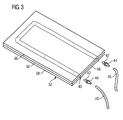
- the insulating layer 32 of the busbar 8 is provided with a cavity 40 ( FIG. 3 ).
- This cavity 40 is connected in terms of coolant with the liquid circuit of the liquid heat sink 6.
- the liquid circuit of the liquid-cooling body 6 is referred to as a primary circuit and the liquid circuit of the cavity 40 as a secondary circuit.
- the primary and secondary circuits can be connected in parallel or in series in terms of liquid.
- At least one insulating layer 32 of the busbar 8 of the power converter module is provided with a cavity 40.
- An insulation layer 32 according to the invention is shown in FIG FIG. 3 shown in perspective.
- This insulating layer 32 has two insulating layers 36 and 38 which are materially interconnected. In this case, these two insulating layers 36 and 38 are integrally connected to each other in such a way that a cavity 40 is formed.
- this cavity 40 has a desired cross-sectional area, 40 compressed air is introduced into this cavity. As a result, this cavity 40 is inflated.
- the cross-sectional area of the cavity 40 is approximately constant over its entire length, these two cohesively interconnected insulating layers 36 and 38 are inserted in a mold.
- An advantageous cross-sectional area of the cavity 40 is rectangular, as this two two-sided busbars 28, 30 are not substantially further apart.
- At least one of the two insulating layers 36 or 38 may be formed as a molded part having a predetermined shaped groove. If both insulating layers 36 and 38 are formed as a molded part, they are mirror-symmetrical to one another. These two molded parts are also connected to one another in a material-locking manner. In the illustrated embodiment ( FIG. 3 ) Each channel of a formed as a molding insulating layer 36 and 38 is semicircular. Since these two formed as a molded part insulating layers 36 and 38 are constructed mirror-symmetrically, created by a cohesive connection of these two insulating layers 36 and 38, an insulating layer 32 with the cavity 40 shown.
- this cavity 40 In order for this cavity 40 to be able to guide coolant through this insulating layer 32, it must be connected to a cooling circuit in terms of fluid.
- Each nozzle 32 has an annular flange 44 in the middle. From this annular flange 44, each end of the nozzle 42 is tapered. As a result, on the one hand, this neck 42 can be plugged into an opening of the cavity 40 without great effort and on the other hand, the hose 46 can be put on the still free end of the nozzle 42 without much effort.
- the annular flange 44 In the mounted state of the nozzle 42, the annular flange 44 is supported on a side surface of the insulating layer 32 from.
- the annular flange 44 of each nozzle 42 is supported on the end face 48 of the insulating layer 32.
- the resulting cavity 40 is U-shaped in the insulating layer 32. That is, both ends of this cavity 40 open in the end face 48 of the insulating layer 32.
- the resulting cavity 40 meander between the two ends in the Front side 48 of the insulation layer 32 extend. It is also possible that the two ends of the cavity 40 open in opposite end faces 48 of the insulating layer 32. It is also conceivable that the two ends of the cavity 40 each open in a narrow surface 50 or in a narrow surface 50 and an end face 48.
- the cooling circuit defined by the cavity 40 is referred to as a secondary circuit.
- the cooling circuit of the liquid heat sink 6 is referred to as a primary circuit.
- this insulation layer 32 formed according to the invention which are stacked and laminated with busbars 26, 28 and 30 to a busbar 8
- the busbar 8 can be cooled such that the power of the power converter module again depends on the performance of the power semiconductor modules 2 and 4 used and no longer on a limit temperature the lamination material used is determined.
- the power converter module according to the invention compared to a commercially available power converter module can be used higher electrically, the permissible temperature for the insulating layer 32 and the laminating material can be maintained.
Landscapes
- Engineering & Computer Science (AREA)
- Microelectronics & Electronic Packaging (AREA)
- Physics & Mathematics (AREA)
- Thermal Sciences (AREA)
- Power Engineering (AREA)
- Cooling Or The Like Of Semiconductors Or Solid State Devices (AREA)
- Rectifiers (AREA)
- Inverter Devices (AREA)
- Cooling Or The Like Of Electrical Apparatus (AREA)
Claims (16)
- Module redresseur de courant ayant au moins deux modules (2, 4) à semiconducteur de puissance, qui sont reliés mécaniquement avec conduction de la chaleur à un dissipateur ( 6 ) de chaleur à liquide et qui sont combinés de manière conductrice de l'électricité au moyen d'un ensemble ( 8 ) de barres, qui comporte au moins deux barres ( 26, 28; 28, 30 ) de courant isolées l'une de l'autre au moyen d'une couche ( 32 ) isolante, à des bornes ( 10, 12, 14 ) du module de convertisseur de courant, caractérisé en ce que la couche ( 32 ) isolante comporte deux couches ( 36, 38 ) isolantes, qui sont reliées l'une à l'autre à complémentarité de matière, de manière à ce qu'il y ait entre ces deux couches ( 36, 38 ) isolantes une cavité ( 40 ), qui est conformée de manière déterminée à l'avance et qui débouche du côté de l'entrée et du côté de la sortie dans au moins une surface ( 48, 50 ) latérale de cette couche ( 32 ) isolante et en ce que cette cavité ( 40 ) est pourvue du côté de l'entrée et du côté de la sortie respectivement d'une tubulure ( 42 ), qui communique respectivement fluidiquement avec le dissipateur ( 6 ) de chaleur à liquide.
- Module redresseur de courant suivant la revendication 1, caractérisé en ce que au moins une couche ( 36, 38 ) isolante est constituée en pièce moulée, de manière à ce que celle-ci ait une goulotte conformée de manière déterminée à l'avance.
- Module redresseur de courant suivant la revendication 1, caractérisé en ce que les deux couches ( 36, 38 ) isolantes formées de pièce moulée sont symétriques comme en un miroir.
- Module redresseur de courant suivant la revendication 1, caractérisé en ce que les barres ( 26, 28, 30 ) de courant et au moins une couche ( 32 ) isolante sont laminées entre elles.
- Module redresseur de courant suivant l'une des revendications précédentes, caractérisé en ce que la cavité ( 40 ) est constituée à la manière d'un tube souple.
- Module redresseur de courant suivant l'une des revendications précédentes, caractérisé en ce que la cavité ( 40 ) est sinueuse.
- Module redresseur de courant suivant l'une des revendications précédentes, caractérisé en ce que la tubulure ( 42 ) a une bride ( 44 ) annulaire.
- Module redresseur de courant suivant la revendication 7, caractérisé en ce que les deux extrémités de la tubulure ( 42 ) s'étendent en se rétrécissant à partir de la bride ( 44 ) annulaire.
- Module redresseur de courant suivant l'une des revendications précédentes, caractérisé en ce que la cavité ( 40 ) est montée, du point de vue du liquide, en parallèle au circuit de refroidissement du dissipateur ( 6 ) de chaleur à liquide.
- Module redresseur de courant suivant l'une des revendications 1 à 8, caractérisé en ce que la cavité ( 40 ) est montée, du point de vue du liquide, en série avec le circuit de refroidissement du dissipateur ( 6 ) de chaleur à liquide.
- Module redresseur de courant suivant l'une des revendications précédentes, caractérisé en ce que la cavité ( 40 ) a une surface de section transversale circulaire.
- Module redresseur de courant suivant l'une des revendications 1 à 10, caractérisé en ce que la cavité ( 40 ) a une surface de section transversale rectangulaire.
- Module redresseur de courant suivant la revendication 2, caractérisé en ce que la goulotte est en forme de V.
- Module redresseur de courant suivant la revendication 2, caractérisé en ce que la goulotte est de forme hémicirculaire.
- Module redresseur de courant suivant la revendication 2, caractérisé en ce que la goulotte est en forme de U.
- Module redresseur de courant suivant la revendication 2, caractérisé en ce que la cavité ( 40 ) a par endroit des surfaces de section transversale différentes.
Applications Claiming Priority (2)
| Application Number | Priority Date | Filing Date | Title |
|---|---|---|---|
| DE102008061468A DE102008061468A1 (de) | 2008-12-10 | 2008-12-10 | Stromrichtermodul mit gekühlter Verschienung |
| PCT/EP2009/062579 WO2010066483A1 (fr) | 2008-12-10 | 2009-09-29 | Module redresseur de courant à système de barres refroidi |
Publications (2)
| Publication Number | Publication Date |
|---|---|
| EP2364580A1 EP2364580A1 (fr) | 2011-09-14 |
| EP2364580B1 true EP2364580B1 (fr) | 2012-10-17 |
Family
ID=41394851
Family Applications (1)
| Application Number | Title | Priority Date | Filing Date |
|---|---|---|---|
| EP09783520A Not-in-force EP2364580B1 (fr) | 2008-12-10 | 2009-09-29 | Module redresseur de courant à système de barres refroidi |
Country Status (6)
| Country | Link |
|---|---|
| US (1) | US8432694B2 (fr) |
| EP (1) | EP2364580B1 (fr) |
| CN (1) | CN102246611B (fr) |
| DE (1) | DE102008061468A1 (fr) |
| RU (1) | RU2504864C2 (fr) |
| WO (1) | WO2010066483A1 (fr) |
Cited By (1)
| Publication number | Priority date | Publication date | Assignee | Title |
|---|---|---|---|---|
| WO2025162662A1 (fr) * | 2024-01-29 | 2025-08-07 | Zf Friedrichshafen Ag | Système de barre omnibus |
Families Citing this family (26)
| Publication number | Priority date | Publication date | Assignee | Title |
|---|---|---|---|---|
| DE102010039676B4 (de) * | 2010-08-24 | 2016-06-09 | Mahle International Gmbh | Kühlsystem zum Kühlen von Elektronikkomponenten |
| AU2012232968B2 (en) | 2011-10-31 | 2014-11-13 | Abb Technology Ag | Thermosiphon cooler arrangement in modules with electric and/or electronic components |
| AU2012232967B2 (en) * | 2011-10-31 | 2015-01-15 | Abb Technology Ag | Cabinet with modules having a thermosiphon cooler arrangement |
| JP5813137B2 (ja) * | 2011-12-26 | 2015-11-17 | 三菱電機株式会社 | 電力用半導体装置及びその製造方法 |
| WO2013100913A1 (fr) * | 2011-12-27 | 2013-07-04 | Intel Corporation | Systèmes de gestion de la thermique transitoire pour dispositifs à semi-conducteurs |
| JP5880519B2 (ja) * | 2013-10-21 | 2016-03-09 | トヨタ自動車株式会社 | 車載電子装置 |
| CN104750207A (zh) * | 2013-12-30 | 2015-07-01 | 鸿富锦精密工业(武汉)有限公司 | 散热模组 |
| US20230020152A1 (en) * | 2014-07-18 | 2023-01-19 | Yue Zhang | Plate vapor chamber array assembly |
| CN105451503B (zh) * | 2014-07-21 | 2019-03-08 | 联想(北京)有限公司 | 一种电子设备 |
| CN105450042B (zh) * | 2014-09-26 | 2018-04-17 | 台达电子工业股份有限公司 | 三电平功率变换器及其功率单元 |
| US20160165754A1 (en) * | 2014-12-03 | 2016-06-09 | Vincent Yu | Water cooling heat sink unit |
| EP3048716A1 (fr) | 2015-01-20 | 2016-07-27 | Siemens Aktiengesellschaft | Agencement de convertisseur doté de contacts mobiles, doté cependant d'un bloc de convertisseur fixe |
| JP6435905B2 (ja) * | 2015-02-13 | 2018-12-12 | 株式会社デンソー | 電力変換装置 |
| DE102015105347B4 (de) * | 2015-04-09 | 2022-03-24 | Semikron Elektronik Gmbh & Co. Kg | Anordnung mit einem leitstungselektronischen Bauteil und mit einer Gleichspannungsverschienung |
| DE102015220792A1 (de) * | 2015-10-23 | 2017-04-27 | Zf Friedrichshafen Ag | Leistungselektronikanordnung |
| EP3163612B1 (fr) * | 2015-10-27 | 2021-05-05 | ABB Schweiz AG | Élément de refroidissement pour composants électroniques et dispositif électronique |
| EP3185660A1 (fr) * | 2015-12-22 | 2017-06-28 | Siemens Aktiengesellschaft | Agencement de rails conducteurs |
| CN109155592B (zh) | 2016-04-28 | 2021-01-01 | 日产自动车株式会社 | 车载用电力变换装置 |
| JP6604289B2 (ja) * | 2016-08-30 | 2019-11-13 | 株式会社オートネットワーク技術研究所 | 電気接続箱 |
| US10021802B2 (en) | 2016-09-19 | 2018-07-10 | General Electric Company | Electronic module assembly having low loop inductance |
| CN108122866B (zh) * | 2016-11-28 | 2019-11-29 | 中车株洲电力机车研究所有限公司 | 一种集成化功率模块 |
| CN108122871B (zh) * | 2016-11-28 | 2019-11-29 | 中车株洲电力机车研究所有限公司 | 一种h桥臂双面散热功率模块 |
| EP3415856A1 (fr) * | 2017-06-13 | 2018-12-19 | Nokia Solutions and Networks Oy | Échangeur de chaleur modulaire et son procédé de fabrication |
| DE102018201451A1 (de) | 2018-01-31 | 2019-08-01 | MTU Aero Engines AG | Gleitkontaktkomponente für eine Induktionsheizvorrichtung, Induktionsheizvorrichtung mit einer Gleitkontaktkomponente und Verfahren zur Herstellung einer Gleitkontaktkomponente |
| US10680533B1 (en) * | 2019-02-01 | 2020-06-09 | Hamilton Sunstrand Corporation | Common layout rectifier or converter |
| CN113823932B (zh) * | 2020-06-18 | 2025-07-18 | 莫列斯有限公司 | 连接器组件 |
Family Cites Families (25)
| Publication number | Priority date | Publication date | Assignee | Title |
|---|---|---|---|---|
| JPS5325644A (en) | 1976-08-20 | 1978-03-09 | Sumitomo Metal Ind | Process for granulation of melted metallurgical slag |
| US4381032A (en) * | 1981-04-23 | 1983-04-26 | Cutchaw John M | Apparatus for cooling high-density integrated circuit packages |
| JPH02151056A (ja) * | 1988-12-02 | 1990-06-11 | Hitachi Ltd | 半導体装置用電源基板の製作方法 |
| JPH05325644A (ja) * | 1992-05-18 | 1993-12-10 | Fujitsu Ltd | 電源バスバーの構造 |
| US5804761A (en) * | 1996-05-02 | 1998-09-08 | Chrysler Corporation | Water cooled DC bus structure |
| US5694301A (en) * | 1996-05-02 | 1997-12-02 | Chrysler Corporation | Power structure construction (DC bus cross straps) |
| US5923085A (en) * | 1996-05-02 | 1999-07-13 | Chrysler Corporation | IGBT module construction |
| DE19654376B4 (de) | 1996-12-24 | 2005-08-04 | Thyssen Krupp Automotive Gmbh | Seitenaufprallträger für Kfz-Türen |
| DE29813254U1 (de) | 1998-07-24 | 1998-10-01 | Siemens AG, 80333 München | Mehrphasiger Dreipunkt-Stromrichter |
| DE19833491A1 (de) * | 1998-07-24 | 2000-02-03 | Siemens Ag | Niederinduktive Verschienung für einen Dreipunkt-Phasenbaustein |
| US20030218057A1 (en) * | 2000-11-07 | 2003-11-27 | Craig Joseph | Electrical bus with associated porous metal heat sink and method of manufacturing same |
| JP3851098B2 (ja) * | 2001-02-26 | 2006-11-29 | 株式会社日立製作所 | 電力変換装置 |
| US6574094B1 (en) * | 2002-04-11 | 2003-06-03 | General Dynamics Land Systems Inc. | Method and apparatus for cooling bus bars |
| RU2229757C2 (ru) * | 2002-07-29 | 2004-05-27 | Таланин Юрий Васильевич | Устройство для нагрева и охлаждения радиоэлектронной аппаратуры |
| US6885553B2 (en) * | 2002-09-27 | 2005-04-26 | Rockwell Automation Technologies, Inc. | Bus bar assembly for use with a compact power conversion assembly |
| DE102004018469B3 (de) | 2004-04-16 | 2005-10-06 | eupec Europäische Gesellschaft für Leistungshalbleiter mbH | Leistungshalbleiterschaltung |
| RU2280294C2 (ru) * | 2004-10-11 | 2006-07-20 | Юрий Васильевич Таланин | Силовой блок |
| US7393236B2 (en) * | 2005-09-02 | 2008-07-01 | Gm Global Technology Operations, Inc. | Integrated thermal and electrical connection system for power devices |
| CN100378976C (zh) * | 2005-10-25 | 2008-04-02 | 中国南车集团株洲电力机车研究所 | 一种电传动电力电子功率变换器水冷方法及装置 |
| CN2842826Y (zh) * | 2005-10-27 | 2006-11-29 | 中国南车集团株洲电力机车研究所 | 一种电传动电力电子功率变换器水冷散热板 |
| JP4751810B2 (ja) * | 2006-11-02 | 2011-08-17 | 日立オートモティブシステムズ株式会社 | 電力変換装置 |
| US8007255B2 (en) * | 2006-11-22 | 2011-08-30 | Mitsubishi Heavy Industries, Ltd. | Inverter-integrated electric compressor with inverter storage box arrangement |
| DE102007003875A1 (de) | 2007-01-25 | 2008-08-07 | Siemens Ag | Stromrichter |
| JP4452953B2 (ja) * | 2007-08-09 | 2010-04-21 | 日立オートモティブシステムズ株式会社 | 電力変換装置 |
| US7952875B2 (en) * | 2009-05-29 | 2011-05-31 | GM Global Technology Operations LLC | Stacked busbar assembly with integrated cooling |
-
2008
- 2008-12-10 DE DE102008061468A patent/DE102008061468A1/de not_active Withdrawn
-
2009
- 2009-09-29 US US13/133,798 patent/US8432694B2/en not_active Expired - Fee Related
- 2009-09-29 WO PCT/EP2009/062579 patent/WO2010066483A1/fr not_active Ceased
- 2009-09-29 RU RU2011127997/07A patent/RU2504864C2/ru active
- 2009-09-29 CN CN200980149443.4A patent/CN102246611B/zh active Active
- 2009-09-29 EP EP09783520A patent/EP2364580B1/fr not_active Not-in-force
Cited By (1)
| Publication number | Priority date | Publication date | Assignee | Title |
|---|---|---|---|---|
| WO2025162662A1 (fr) * | 2024-01-29 | 2025-08-07 | Zf Friedrichshafen Ag | Système de barre omnibus |
Also Published As
| Publication number | Publication date |
|---|---|
| DE102008061468A1 (de) | 2010-06-17 |
| CN102246611A (zh) | 2011-11-16 |
| US8432694B2 (en) | 2013-04-30 |
| EP2364580A1 (fr) | 2011-09-14 |
| RU2011127997A (ru) | 2013-01-20 |
| RU2504864C2 (ru) | 2014-01-20 |
| CN102246611B (zh) | 2014-09-10 |
| US20110249402A1 (en) | 2011-10-13 |
| WO2010066483A1 (fr) | 2010-06-17 |
Similar Documents
| Publication | Publication Date | Title |
|---|---|---|
| EP2364580B1 (fr) | Module redresseur de courant à système de barres refroidi | |
| EP2356894B1 (fr) | Module redresseur de courant avec rails refroidis | |
| EP2364581B1 (fr) | Module redresseur de courant à système de barres refroidi | |
| DE102008064789B3 (de) | Harzabgedichtete Halbleitervorrichtung | |
| DE102010000082B4 (de) | Schaltungsanordnung von elektronischen Leistungsschaltern einer Stromerzeugungsvorrichtung | |
| EP2654392B1 (fr) | Module semi-conducteur de puissance refroidi par liquide pouvant être joint et agencement à cet effet | |
| DE102013215124B4 (de) | Halbleitereinheit | |
| DE102013213205A1 (de) | Halbleitereinheit | |
| DE102007003875A1 (de) | Stromrichter | |
| DE102020119169B4 (de) | Schaltkomponenten | |
| DE102008031491A1 (de) | Kondensator mit direkter DC-Verbindung zum Substrat | |
| DE102016108562A1 (de) | Halbleiter-bauelement mit gestapelten anschlüssen | |
| DE112016006460B4 (de) | Leistungshalbleitermodul | |
| DE202012012767U1 (de) | Leistungshalbleitermodulsystem | |
| EP2521432A2 (fr) | Agencement de puissance électronique doté d'un refroidissement de liquide | |
| DE102022123261B4 (de) | Leistungselektronische Baugruppe mit einem Gehäuse und mit einer darin angeordneten Kondensatoreinrichtung | |
| DE102015216083A1 (de) | Modulanordnung zum induktivitätsarmen Betrieb eines Leistungshalbleitermoduls an einem Gleichspannungskreis | |
| DE102021213427B3 (de) | Kompaktes leistungswechselrichtermodul | |
| DE102017106515A1 (de) | 3-Pegel-Leistungsmodul | |
| DE102022201329A1 (de) | Schaltermodul für einen Inverter, Inverter mit mehreren solchen Schaltermodulen sowie Fahrzeug mit dem Inverter | |
| DE102013103866B3 (de) | Leistungshalbleitereinrichtung | |
| DE102023206563A1 (de) | Leistungshalbleiteranordnung mit direkter Leistungshalbleiterkühlung | |
| DE102023203213A1 (de) | Substrat zum Anbringen von Leistungsschaltern für einen Stromrichter mit optimierter elektrischer Isolation | |
| DE102022204342A1 (de) | Gehäuseelement einer Batterie und Batterie mit einem solchen | |
| DE102023110166A1 (de) | Halbleiterleistungsmodul |
Legal Events
| Date | Code | Title | Description |
|---|---|---|---|
| PUAI | Public reference made under article 153(3) epc to a published international application that has entered the european phase |
Free format text: ORIGINAL CODE: 0009012 |
|
| 17P | Request for examination filed |
Effective date: 20110330 |
|
| AK | Designated contracting states |
Kind code of ref document: A1 Designated state(s): AT BE BG CH CY CZ DE DK EE ES FI FR GB GR HR HU IE IS IT LI LT LU LV MC MK MT NL NO PL PT RO SE SI SK SM TR |
|
| DAX | Request for extension of the european patent (deleted) | ||
| GRAP | Despatch of communication of intention to grant a patent |
Free format text: ORIGINAL CODE: EPIDOSNIGR1 |
|
| GRAS | Grant fee paid |
Free format text: ORIGINAL CODE: EPIDOSNIGR3 |
|
| GRAA | (expected) grant |
Free format text: ORIGINAL CODE: 0009210 |
|
| AK | Designated contracting states |
Kind code of ref document: B1 Designated state(s): AT BE BG CH CY CZ DE DK EE ES FI FR GB GR HR HU IE IS IT LI LT LU LV MC MK MT NL NO PL PT RO SE SI SK SM TR |
|
| REG | Reference to a national code |
Ref country code: GB Ref legal event code: FG4D Free format text: NOT ENGLISH |
|
| REG | Reference to a national code |
Ref country code: CH Ref legal event code: NV Representative=s name: SIEMENS SCHWEIZ AG Ref country code: CH Ref legal event code: EP |
|
| REG | Reference to a national code |
Ref country code: IE Ref legal event code: FG4D Free format text: LANGUAGE OF EP DOCUMENT: GERMAN |
|
| REG | Reference to a national code |
Ref country code: AT Ref legal event code: REF Ref document number: 580379 Country of ref document: AT Kind code of ref document: T Effective date: 20121115 |
|
| REG | Reference to a national code |
Ref country code: DE Ref legal event code: R096 Ref document number: 502009005144 Country of ref document: DE Effective date: 20121213 |
|
| RAP2 | Party data changed (patent owner data changed or rights of a patent transferred) |
Owner name: SIEMENS AKTIENGESELLSCHAFT |
|
| REG | Reference to a national code |
Ref country code: NL Ref legal event code: VDEP Effective date: 20121017 |
|
| REG | Reference to a national code |
Ref country code: LT Ref legal event code: MG4D |
|
| PG25 | Lapsed in a contracting state [announced via postgrant information from national office to epo] |
Ref country code: LT Free format text: LAPSE BECAUSE OF FAILURE TO SUBMIT A TRANSLATION OF THE DESCRIPTION OR TO PAY THE FEE WITHIN THE PRESCRIBED TIME-LIMIT Effective date: 20121017 Ref country code: IS Free format text: LAPSE BECAUSE OF FAILURE TO SUBMIT A TRANSLATION OF THE DESCRIPTION OR TO PAY THE FEE WITHIN THE PRESCRIBED TIME-LIMIT Effective date: 20130217 Ref country code: HR Free format text: LAPSE BECAUSE OF FAILURE TO SUBMIT A TRANSLATION OF THE DESCRIPTION OR TO PAY THE FEE WITHIN THE PRESCRIBED TIME-LIMIT Effective date: 20121017 Ref country code: FI Free format text: LAPSE BECAUSE OF FAILURE TO SUBMIT A TRANSLATION OF THE DESCRIPTION OR TO PAY THE FEE WITHIN THE PRESCRIBED TIME-LIMIT Effective date: 20121017 Ref country code: NL Free format text: LAPSE BECAUSE OF FAILURE TO SUBMIT A TRANSLATION OF THE DESCRIPTION OR TO PAY THE FEE WITHIN THE PRESCRIBED TIME-LIMIT Effective date: 20121017 Ref country code: SE Free format text: LAPSE BECAUSE OF FAILURE TO SUBMIT A TRANSLATION OF THE DESCRIPTION OR TO PAY THE FEE WITHIN THE PRESCRIBED TIME-LIMIT Effective date: 20121017 Ref country code: NO Free format text: LAPSE BECAUSE OF FAILURE TO SUBMIT A TRANSLATION OF THE DESCRIPTION OR TO PAY THE FEE WITHIN THE PRESCRIBED TIME-LIMIT Effective date: 20130117 |
|
| PG25 | Lapsed in a contracting state [announced via postgrant information from national office to epo] |
Ref country code: SI Free format text: LAPSE BECAUSE OF FAILURE TO SUBMIT A TRANSLATION OF THE DESCRIPTION OR TO PAY THE FEE WITHIN THE PRESCRIBED TIME-LIMIT Effective date: 20121017 Ref country code: PT Free format text: LAPSE BECAUSE OF FAILURE TO SUBMIT A TRANSLATION OF THE DESCRIPTION OR TO PAY THE FEE WITHIN THE PRESCRIBED TIME-LIMIT Effective date: 20130218 Ref country code: LV Free format text: LAPSE BECAUSE OF FAILURE TO SUBMIT A TRANSLATION OF THE DESCRIPTION OR TO PAY THE FEE WITHIN THE PRESCRIBED TIME-LIMIT Effective date: 20121017 Ref country code: PL Free format text: LAPSE BECAUSE OF FAILURE TO SUBMIT A TRANSLATION OF THE DESCRIPTION OR TO PAY THE FEE WITHIN THE PRESCRIBED TIME-LIMIT Effective date: 20121017 Ref country code: GR Free format text: LAPSE BECAUSE OF FAILURE TO SUBMIT A TRANSLATION OF THE DESCRIPTION OR TO PAY THE FEE WITHIN THE PRESCRIBED TIME-LIMIT Effective date: 20130118 |
|
| PG25 | Lapsed in a contracting state [announced via postgrant information from national office to epo] |
Ref country code: CZ Free format text: LAPSE BECAUSE OF FAILURE TO SUBMIT A TRANSLATION OF THE DESCRIPTION OR TO PAY THE FEE WITHIN THE PRESCRIBED TIME-LIMIT Effective date: 20121017 Ref country code: BG Free format text: LAPSE BECAUSE OF FAILURE TO SUBMIT A TRANSLATION OF THE DESCRIPTION OR TO PAY THE FEE WITHIN THE PRESCRIBED TIME-LIMIT Effective date: 20130117 Ref country code: SK Free format text: LAPSE BECAUSE OF FAILURE TO SUBMIT A TRANSLATION OF THE DESCRIPTION OR TO PAY THE FEE WITHIN THE PRESCRIBED TIME-LIMIT Effective date: 20121017 Ref country code: DK Free format text: LAPSE BECAUSE OF FAILURE TO SUBMIT A TRANSLATION OF THE DESCRIPTION OR TO PAY THE FEE WITHIN THE PRESCRIBED TIME-LIMIT Effective date: 20121017 Ref country code: EE Free format text: LAPSE BECAUSE OF FAILURE TO SUBMIT A TRANSLATION OF THE DESCRIPTION OR TO PAY THE FEE WITHIN THE PRESCRIBED TIME-LIMIT Effective date: 20121017 |
|
| PLBE | No opposition filed within time limit |
Free format text: ORIGINAL CODE: 0009261 |
|
| STAA | Information on the status of an ep patent application or granted ep patent |
Free format text: STATUS: NO OPPOSITION FILED WITHIN TIME LIMIT |
|
| PG25 | Lapsed in a contracting state [announced via postgrant information from national office to epo] |
Ref country code: IT Free format text: LAPSE BECAUSE OF FAILURE TO SUBMIT A TRANSLATION OF THE DESCRIPTION OR TO PAY THE FEE WITHIN THE PRESCRIBED TIME-LIMIT Effective date: 20121017 Ref country code: RO Free format text: LAPSE BECAUSE OF FAILURE TO SUBMIT A TRANSLATION OF THE DESCRIPTION OR TO PAY THE FEE WITHIN THE PRESCRIBED TIME-LIMIT Effective date: 20121017 |
|
| 26N | No opposition filed |
Effective date: 20130718 |
|
| PG25 | Lapsed in a contracting state [announced via postgrant information from national office to epo] |
Ref country code: ES Free format text: LAPSE BECAUSE OF FAILURE TO SUBMIT A TRANSLATION OF THE DESCRIPTION OR TO PAY THE FEE WITHIN THE PRESCRIBED TIME-LIMIT Effective date: 20130128 |
|
| REG | Reference to a national code |
Ref country code: DE Ref legal event code: R097 Ref document number: 502009005144 Country of ref document: DE Effective date: 20130718 |
|
| PG25 | Lapsed in a contracting state [announced via postgrant information from national office to epo] |
Ref country code: CY Free format text: LAPSE BECAUSE OF FAILURE TO SUBMIT A TRANSLATION OF THE DESCRIPTION OR TO PAY THE FEE WITHIN THE PRESCRIBED TIME-LIMIT Effective date: 20121017 |
|
| BERE | Be: lapsed |
Owner name: SIEMENS A.G. Effective date: 20130930 |
|
| PG25 | Lapsed in a contracting state [announced via postgrant information from national office to epo] |
Ref country code: MC Free format text: LAPSE BECAUSE OF FAILURE TO SUBMIT A TRANSLATION OF THE DESCRIPTION OR TO PAY THE FEE WITHIN THE PRESCRIBED TIME-LIMIT Effective date: 20121017 |
|
| REG | Reference to a national code |
Ref country code: IE Ref legal event code: MM4A |
|
| PG25 | Lapsed in a contracting state [announced via postgrant information from national office to epo] |
Ref country code: IE Free format text: LAPSE BECAUSE OF NON-PAYMENT OF DUE FEES Effective date: 20130929 Ref country code: BE Free format text: LAPSE BECAUSE OF NON-PAYMENT OF DUE FEES Effective date: 20130930 |
|
| PG25 | Lapsed in a contracting state [announced via postgrant information from national office to epo] |
Ref country code: SM Free format text: LAPSE BECAUSE OF FAILURE TO SUBMIT A TRANSLATION OF THE DESCRIPTION OR TO PAY THE FEE WITHIN THE PRESCRIBED TIME-LIMIT Effective date: 20121017 |
|
| PG25 | Lapsed in a contracting state [announced via postgrant information from national office to epo] |
Ref country code: TR Free format text: LAPSE BECAUSE OF FAILURE TO SUBMIT A TRANSLATION OF THE DESCRIPTION OR TO PAY THE FEE WITHIN THE PRESCRIBED TIME-LIMIT Effective date: 20121017 Ref country code: MT Free format text: LAPSE BECAUSE OF FAILURE TO SUBMIT A TRANSLATION OF THE DESCRIPTION OR TO PAY THE FEE WITHIN THE PRESCRIBED TIME-LIMIT Effective date: 20121017 |
|
| PG25 | Lapsed in a contracting state [announced via postgrant information from national office to epo] |
Ref country code: LU Free format text: LAPSE BECAUSE OF NON-PAYMENT OF DUE FEES Effective date: 20130929 Ref country code: HU Free format text: LAPSE BECAUSE OF FAILURE TO SUBMIT A TRANSLATION OF THE DESCRIPTION OR TO PAY THE FEE WITHIN THE PRESCRIBED TIME-LIMIT; INVALID AB INITIO Effective date: 20090929 Ref country code: MK Free format text: LAPSE BECAUSE OF FAILURE TO SUBMIT A TRANSLATION OF THE DESCRIPTION OR TO PAY THE FEE WITHIN THE PRESCRIBED TIME-LIMIT Effective date: 20121017 |
|
| REG | Reference to a national code |
Ref country code: FR Ref legal event code: PLFP Year of fee payment: 8 |
|
| REG | Reference to a national code |
Ref country code: FR Ref legal event code: PLFP Year of fee payment: 9 |
|
| REG | Reference to a national code |
Ref country code: CH Ref legal event code: PCOW Free format text: NEW ADDRESS: WERNER-VON-SIEMENS-STRASSE 1, 80333 MUENCHEN (DE) |
|
| REG | Reference to a national code |
Ref country code: FR Ref legal event code: PLFP Year of fee payment: 10 |
|
| PGFP | Annual fee paid to national office [announced via postgrant information from national office to epo] |
Ref country code: FR Payment date: 20200921 Year of fee payment: 12 |
|
| PGFP | Annual fee paid to national office [announced via postgrant information from national office to epo] |
Ref country code: AT Payment date: 20200813 Year of fee payment: 12 |
|
| PGFP | Annual fee paid to national office [announced via postgrant information from national office to epo] |
Ref country code: DE Payment date: 20201118 Year of fee payment: 12 Ref country code: GB Payment date: 20201002 Year of fee payment: 12 Ref country code: CH Payment date: 20201202 Year of fee payment: 12 |
|
| REG | Reference to a national code |
Ref country code: DE Ref legal event code: R119 Ref document number: 502009005144 Country of ref document: DE |
|
| REG | Reference to a national code |
Ref country code: CH Ref legal event code: PL |
|
| REG | Reference to a national code |
Ref country code: AT Ref legal event code: MM01 Ref document number: 580379 Country of ref document: AT Kind code of ref document: T Effective date: 20210929 |
|
| GBPC | Gb: european patent ceased through non-payment of renewal fee |
Effective date: 20210929 |
|
| PG25 | Lapsed in a contracting state [announced via postgrant information from national office to epo] |
Ref country code: GB Free format text: LAPSE BECAUSE OF NON-PAYMENT OF DUE FEES Effective date: 20210929 Ref country code: FR Free format text: LAPSE BECAUSE OF NON-PAYMENT OF DUE FEES Effective date: 20210930 Ref country code: DE Free format text: LAPSE BECAUSE OF NON-PAYMENT OF DUE FEES Effective date: 20220401 |
|
| PG25 | Lapsed in a contracting state [announced via postgrant information from national office to epo] |
Ref country code: LI Free format text: LAPSE BECAUSE OF NON-PAYMENT OF DUE FEES Effective date: 20210930 Ref country code: CH Free format text: LAPSE BECAUSE OF NON-PAYMENT OF DUE FEES Effective date: 20210930 Ref country code: AT Free format text: LAPSE BECAUSE OF NON-PAYMENT OF DUE FEES Effective date: 20210929 |