EP2521432A2 - Agencement de puissance électronique doté d'un refroidissement de liquide - Google Patents
Agencement de puissance électronique doté d'un refroidissement de liquide Download PDFInfo
- Publication number
- EP2521432A2 EP2521432A2 EP12159006A EP12159006A EP2521432A2 EP 2521432 A2 EP2521432 A2 EP 2521432A2 EP 12159006 A EP12159006 A EP 12159006A EP 12159006 A EP12159006 A EP 12159006A EP 2521432 A2 EP2521432 A2 EP 2521432A2
- Authority
- EP
- European Patent Office
- Prior art keywords
- cooling device
- liquid
- liquid cooling
- electrical
- power semiconductor
- Prior art date
- Legal status (The legal status is an assumption and is not a legal conclusion. Google has not performed a legal analysis and makes no representation as to the accuracy of the status listed.)
- Withdrawn
Links
Images



Classifications
-
- H—ELECTRICITY
- H05—ELECTRIC TECHNIQUES NOT OTHERWISE PROVIDED FOR
- H05K—PRINTED CIRCUITS; CASINGS OR CONSTRUCTIONAL DETAILS OF ELECTRIC APPARATUS; MANUFACTURE OF ASSEMBLAGES OF ELECTRICAL COMPONENTS
- H05K7/00—Constructional details common to different types of electric apparatus
- H05K7/20—Modifications to facilitate cooling, ventilating, or heating
- H05K7/2089—Modifications to facilitate cooling, ventilating, or heating for power electronics, e.g. for inverters for controlling motor
- H05K7/20927—Liquid coolant without phase change
Definitions
- the invention relates to a power electronic device comprising liquid-cooled power semiconductor modules and a fluid cooling device connected to a coolant circuit.
- cooling liquid has proven itself, because the removal of the resulting heat loss in the semiconductor devices by means of cooling liquid is very effective and the cooling liquid with relatively little effort to the component to be cooled can be moved.
- the object of the present invention is to provide an improved power electronic arrangement with liquid cooling.
- a power electronic device comprising two or more liquid-cooled power semiconductor modules and connectable to a coolant circuit liquid cooling device, wherein the power semiconductor modules are arranged on the liquid cooling device, wherein it is provided that the power semiconductor modules each have at least one electrical connector connected to one of several the liquid cooling device arranged electrical connectors is connectable, wherein the plurality of connectors are electrically connected to each other by a bus forming electrical connection lines, and that the liquid cooling means comprises a duct for receiving the electrical connection lines and the plurality of electrical connectors.
- the power electronic arrangement is characterized in that the liquid cooling device has a plurality of electrical connectors which are electrically connected to each other by a bus forming electrical connection lines, so that the assembly and possibly disassembly of the modules on the liquid cooling device is possible very quickly and without errors.
- the cooling liquid circuit comprises, in addition to the liquid cooling device on which the power semiconductor modules are arranged, a coolant pump and a heat exchanger in which the cooling liquid heated in the power semiconductor modules is cooled.
- the liquid cooling device has two throughflow passages for a cooling liquid which are connected to cooling liquid outlets or to cooling liquid inlets which are arranged on the upper side of the liquid cooling device such that the power semiconductor modules have a module-side cooling liquid inlet and a module-side cooling liquid outlet, and that the power semiconductor modules are liquid-tight connectable by placing on the liquid cooling device with the passageways.
- connecting elements for the passage of the cooling liquid are provided both on the liquid cooling device and on the power semiconductor modules, wherein advantageously a sealing element can be provided between two corresponding connecting elements.
- the sealing element can be formed, for example, as an O-ring or a flat sealing element made of rubber or the like, as an adhesive pad or as an adhesive layer, for example of silicone rubber.
- the duct can pass through the liquid cooling device parallel to its longitudinal axis.
- the duct is arranged between the two passage channels.
- the plurality of electrical connectors of the liquid cooling device are arranged on a bus circuit board, and that the electrical connection lines are formed as a conductor tracks of the bus circuit board. It may preferably be a strip-shaped printed circuit board.
- the plurality of electrical connectors can at least partially pass through through holes arranged in the upper side of the liquid cooling device.
- the duct may have a rectangular cross-section, which may be dimensioned so that the bus circuit board is axially inserted into the duct.
- the clear width of the duct may be the width of the bus board and the clear height of the duct may correspond to the height of the bus board plus the height of the arranged on the bus board electrical connector.
- a preferably formed of electrically insulating material spacer can be arranged, which raises the bus board so far that the electrical connector at least partially pass through the through holes in the top of the liquid cooling device.
- the inner contour of the through holes may be formed congruent to the outer contour of the at least one connector of the power semiconductor modules and the at least one connector of the control module described below.
- the inner contour of the through holes acts as a guide when placing the aforementioned modules on the liquid cooling device.
- the at least one electrical connector of the power semiconductor module is designed as an electrical socket and the corresponding electrical connector of the plurality of electrical connectors of the liquid cooling device as an electrical connector plug or vice versa.
- the at least one electrical connector of the power semiconductor module is electrically connectable to the corresponding connector of the plurality of electrical connectors of the liquid cooling device by placing the power semiconductor module on the liquid cooling device.
- the electronic power device further comprises a control module which is arranged on the liquid cooling device, and that the control module has at least one electrical connector which is connectable to one of the plurality of electrical connectors arranged on the liquid cooling device.
- the control module may have further electrical connections in order, for example, to connect it to a higher-level control and / or control unit and / or to an input unit for control commands.
- the at least one electrical connector of the control module can be designed as an electrical socket and the corresponding connector of the plurality of electrical connectors of the liquid cooling device can be designed as an electrical connector or vice versa.
- the at least one electrical connector of the control module with the corresponding electrical connector of the liquid cooling device is electrically connectable by placing the control module on the liquid cooling device.
- the power semiconductor modules and / or the control module can be designed polarity reversal.
- the modules and / or the liquid cooling device may have mechanical devices which prevent false allocations of the current paths being produced. It can also be provided built-in connector, which can be inserted only in one position to the socket. For example, lugs may be provided or the arrangement of the plug pins may be selected so that only one plug variant is permitted.
- the electrical connectors for controlling the power semiconductor module and the module-side cooling fluid inlet and the module-side cooling fluid outlet are arranged on the bottom side of the power semiconductor module and DC voltage connections and AC voltage connections for integrating the power semiconductor module opposite one another at the two end sides in a power circuit.
- the power semiconductor modules are arranged close to each other with side faces facing each other.
- the DC voltage connections on the one side and the AC voltage connections on the other side are also arranged in the power electronic arrangement thus formed, whereby, for example, a cascading of the power semiconductor modules is particularly is simply possible.
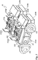
- Fig. 1 shows a power electronic device 1, which can be used for example as a converter unit for wind turbines.
- the power electronic device 1 is modular and includes in the in Fig. 1 illustrated embodiment in six half-bridge circuit formed liquid-cooled power semiconductor modules 11, wherein because of the sectional view in Fig. 1 only four power semiconductor modules are shown.
- the power semiconductor modules 11 are arranged side by side on a mounting surface of a liquid cooling device 12.
- the liquid cooling device 12 is substantially formed as a plate-shaped mounting body and penetrated by two parallel passageways 121 for the cooling liquid.
- the liquid cooling device 12 is integrated in a cooling liquid circuit, not shown, and serves to distribute a cooling liquid to the power semiconductor modules.
- the cooling liquid is conveyed for example with a coolant pump and cooled in a heat exchanger.
- cold cooling liquid flows in and from the other of the two passageways 121 flows in the power semiconductor modules 11 heated cooling liquid.
- a connecting piece 121 a or a closure piece 121v is arranged in each case. In the in Fig.
- the closure pieces 121v and the connecting pieces 121 a are each arranged on an end face of the liquid cooling device 12. However, it can also be provided to arrange the closure pieces 121v and the connection pieces 121a alternately, so that the cooling liquid enters at one end face of the liquid cooling device 12 and exits at the other end side.
- the passageways 121 are connected to cooling liquid outlets 122 and to cooling liquid inlets 123, respectively, which are arranged at the top of the liquid cooling device 12.
- the power semiconductor modules 11 have on their underside a module-side coolant inlet 111 and a module-side coolant outlet 112.
- the cooling liquid inlet 111 is connected in the assembled state with one of the cooling liquid outlets 122 of the liquid cooling device 12 in a liquid-tight manner.
- Thedestattkeitsauslass 112 is liquid-tightly connected in the assembled state with one of the cooling liquid inlets 123 of the liquid cooling device 12.
- Fig. 3 to recognize the module-side cooling liquid inlet 111 and the module-side cooling liquid outlet 112 are formed nozzle-shaped and protrude from the bottom of the power semiconductor module 11.
- the end faces of the cooling liquid inlet 123 and the cooling liquid outlet 122 of the liquid cooling device 12 have a recess for a sealing element (see Fig.
- the sealing element is, for example, an annular sealing element with a circular cross-section, which is formed of a rubber-elastic material, for example of silicone rubber.
- the sealing element forms a fluid seal between the power semiconductor module 11 and the liquid cooling device 12.
- the corresponding cooling liquid inlets and outlets together with the sealing elements form releasable coolant connection devices.
- it can also be provided to form the sealing elements as adhesive layers, resulting in insoluble or conditionally releasable coolant connection devices.
- the module-side cooling liquid inlet 111 and the module-side cooling liquid outlet 112 may each have threaded holes, in which fastening screws engage.
- the fastening screws pass through through holes in the liquid cooling device 12 and thus connect the power semiconductor module 11 with the liquid cooling device 12, wherein the sealing element is pressed when tightening the fastening screws.
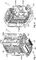
- Fig. 3 shows a partially constructed power semiconductor module 11 without housing, which has four power electronic subsystems 113, which are arranged on a common cooling device 114 in the illustrated example.
- the four subsystems 113 are arranged facing each other on both sides of the cooling device 114 for each of two subsystems.
- the power electronic subsystems 113 may be the above-mentioned half-bridge circuits.
- the cooling device 114 may be formed of a plastic or of metal.
- the cooling device 114 has an inlet section designed as a distribution channel and an outlet section designed as a collector channel for the coolant.
- the input section and the output section are arranged parallel to each other.
- four trough-shaped cooling chambers are arranged, the trough opening of which is respectively covered by the substrate of the power electronic subsystems 113 to be cooled.
- an annular sealing element is arranged (in FIG Fig. 3 not shown), which may be arranged for example in a circumferential groove in the end face of the associated cooling chamber.
- the cooling liquid enters into the cooling means inlet in the module-side cooling liquid inlet 111 at the input of the input section and flows from there into four cooling chambers, in which it comes into direct contact with the substrate of the semiconductor components of the power electronic subsystems 113.
- the cooling liquid is electrically non-conductive.
- the heated cooling liquid exiting the cooling chambers is collected in the exit section of the cooling device 114 and exits at the module-side cooling liquid outlet 112.
- the power electronic subsystems 113 have an internal AC voltage terminal 113wi, two internal DC voltage terminals 113gi (see FIG Fig. 3 ) and two external DC terminals 113ge (see Fig. 1 ).
- the internal DC voltage terminals 113gi are interconnected by means of an internal DC bus 113v (see FIG Fig. 1 ) and with capacitors 113k and connected to the external DC terminals 113ge.
- the capacitors 113 k are mounted in pairs on cooling blocks, which are in thermal contact with the cooling device 114 or are part of the cooling device 114. It may also be provided to form the power semiconductor module 11 without capacitors, wherein the retrofitting with capacitors may be provided as needed.
- the power electronic subsystems 113 have control terminals 113s formed as contact springs and connected to contacts of a control board 113p disposed above the control terminals 113s (see FIG Fig. 4 ) under pressure.
- the control sipe plate 113p faces electrical interconnects connecting the control terminals 113s with contact springs of electrical connectors 115, which are arranged on one of the cooling liquid inlet 111 and thede considerablykeitsauslass 112 facing front side of the control circuit board 113p.
- two control boards 113p are disposed opposite to each other in the housing, as in FIG Fig. 4 to recognize. Each of the two control boards 113p is connected to control terminals 113s of two subsystems 113.
- a control module 13 is further arranged, which controls the power semiconductor modules 11.
- the control module 13 has on its lower end face electrical connectors (in Fig. 1 not shown).
- a strip-shaped bus circuit board 131 is provided, which is arranged in a liquid channel 12 through the cross-duct 124.
- electrical connectors 131 s are arranged, whose contacts are interconnected by interconnects, according to the selected bus system, the connector 131 s are connected in parallel.
- the connectors 131 s, together with the electrical connectors 115 of the power semiconductor module described above detachable electrical connectors, so that the control terminals 124 of the power semiconductor modules 1 are connected to the bus system. It can be provided that the connector 131 s is formed as a socket and the connector 115 as a built-in plug or vice versa.
- the duct 124 passes through the liquid cooling device 12 parallel to its longitudinal axis and is arranged between the two passage channels 121.
- the duct 124 has a rectangular cross-section which is dimensioned so that the bus circuit board 131 is axially inserted into the duct 124.
- the clear width of the duct 124 corresponds to the width of the bus circuit board 131 and the clear height of the duct 124 corresponds to the height of the bus board 131 plus the height of arranged on the bus board 131 electrical connector 131 s.
- the bus board 131 After inserting the bus circuit board 131 in the line channel 124, the bus board 131 is raised so far that the electrical connector 131 s at least partially pass through holes 121 d in the top of the liquid cooling device 12 (see Fig. 2 ).
- the space between the bottom of the bus circuit board 131 and the bottom of the duct 124 may be filled by a spacer element, preferably by a distance element formed of electrically insulating material.
- the inner contour of the through-holes 121d is congruent with the outer contour of the connectors 115 of the power semiconductor modules 11 and the control module 13. The inner contour of the through-holes 121d thus acts as a guide in placing the aforementioned modules on the liquid cooling device 12.
- duct 124 can also be provided to form the duct 124 as an open duct, which can be covered by a cover plate, which can be formed as a spacer at the same time, and to introduce the bus circuit board 131 from the bottom of the liquid cooling device 12.
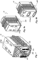
- FIGS. 5 and 6 show an embodiment of a power semiconductor module 11 without capacitors, with only the inner Structure is shown.
- Fig. 5 shows a perspective view with respect to the external DC terminals 113ge.
- Fig. 6 shows a perspective view with respect to external AC terminals 113we.
- the Fig. 7 and 8a and 8b show this in FIGS. 5 and 6 illustrated power semiconductor module 11 with housing.
- FIG. 5 As in Fig. 5 can be seen, four external DC terminals 113ge are provided, wherein preferably the plus and minus terminals are doubly formed and arranged in two superposed rows so that in two adjacent power semiconductor modules 11, the external DC terminals 113ge connected by the shortest route to form a series circuit can be (see Fig. 7 and 8a ).
- the electrical connector 115 for the control of the power semiconductor module 11 and the module-side cooling liquid inlet 111 and the module-sidedestattkeitsauslass 112 are arranged and opposite to each other, the external DC voltage connections 113ge and the two end faces external AC terminals 113we.
- the power semiconductor modules 11 On the liquid cooling device 12, the power semiconductor modules 11 are arranged close to each other with side faces facing each other.
Landscapes
- Engineering & Computer Science (AREA)
- Microelectronics & Electronic Packaging (AREA)
- Physics & Mathematics (AREA)
- Thermal Sciences (AREA)
- Cooling Or The Like Of Electrical Apparatus (AREA)
- Cooling Or The Like Of Semiconductors Or Solid State Devices (AREA)
Applications Claiming Priority (1)
| Application Number | Priority Date | Filing Date | Title |
|---|---|---|---|
| DE102011100526A DE102011100526A1 (de) | 2011-05-05 | 2011-05-05 | Leistungselektronische Anordnung mit Flüssigkeitskühlung |
Publications (1)
| Publication Number | Publication Date |
|---|---|
| EP2521432A2 true EP2521432A2 (fr) | 2012-11-07 |
Family
ID=45977169
Family Applications (1)
| Application Number | Title | Priority Date | Filing Date |
|---|---|---|---|
| EP12159006A Withdrawn EP2521432A2 (fr) | 2011-05-05 | 2012-03-12 | Agencement de puissance électronique doté d'un refroidissement de liquide |
Country Status (3)
| Country | Link |
|---|---|
| EP (1) | EP2521432A2 (fr) |
| CN (2) | CN102769003A (fr) |
| DE (1) | DE102011100526A1 (fr) |
Cited By (5)
| Publication number | Priority date | Publication date | Assignee | Title |
|---|---|---|---|---|
| US20140140005A1 (en) * | 2012-11-20 | 2014-05-22 | Vacon Oyj | Power electronics device |
| CN110816310A (zh) * | 2018-08-10 | 2020-02-21 | 大众汽车有限公司 | 电池模块控制器、其在另外元件处的布置及两者连接方法 |
| DE102019211018A1 (de) * | 2019-07-25 | 2020-09-17 | Zf Friedrichshafen Ag | Fluid kühlbare Baugruppe |
| US10912231B1 (en) * | 2020-01-15 | 2021-02-02 | Ford Global Technologies, Llc | Automotive integrated power module and capacitor |
| FR3113441A1 (fr) * | 2020-08-14 | 2022-02-18 | Valeo Siemens eAutomotive France | Dispositif électrique à refroidissement par boîte à eau et système électrique comportant un tel dispositif |
Families Citing this family (2)
| Publication number | Priority date | Publication date | Assignee | Title |
|---|---|---|---|---|
| DE102011100526A1 (de) * | 2011-05-05 | 2012-11-08 | Semikron Elektronik Gmbh & Co. Kg | Leistungselektronische Anordnung mit Flüssigkeitskühlung |
| DE102020105925B4 (de) | 2020-03-05 | 2024-09-12 | Bayerische Motoren Werke Aktiengesellschaft | Kühlungsanordnung für ein Kraftfahrzeug |
Citations (1)
| Publication number | Priority date | Publication date | Assignee | Title |
|---|---|---|---|---|
| DE602005006310T2 (de) | 2004-11-24 | 2009-05-20 | Danfoss Silicon Power Gmbh | Durchflussverteilungsmodul und Stapel von Durchflussverteilungsmodulen |
Family Cites Families (6)
| Publication number | Priority date | Publication date | Assignee | Title |
|---|---|---|---|---|
| US5001548A (en) * | 1989-03-13 | 1991-03-19 | Coriolis Corporation | Multi-chip module cooling |
| US5428535A (en) * | 1992-09-17 | 1995-06-27 | Kansei Corporation | Vehicle control unit structure |
| FR2716769B1 (fr) * | 1994-02-28 | 1996-05-15 | Peugeot | Dispositif de commande et de contrôle d'un moteur électronique, support utilisable dans un tel dispositif et utilisation de ce support pour la réalisation d'une batterie d'éléments d'accumulateurs électriques. |
| US20080117602A1 (en) * | 2006-11-20 | 2008-05-22 | Korich Mark D | Power inverter having liquid cooled capacitor and low inductance bus structure |
| US20100302729A1 (en) * | 2009-05-27 | 2010-12-02 | Don Tegart | High power solid state power controller packaging |
| DE102011100526A1 (de) * | 2011-05-05 | 2012-11-08 | Semikron Elektronik Gmbh & Co. Kg | Leistungselektronische Anordnung mit Flüssigkeitskühlung |
-
2011
- 2011-05-05 DE DE102011100526A patent/DE102011100526A1/de not_active Withdrawn
-
2012
- 2012-03-12 EP EP12159006A patent/EP2521432A2/fr not_active Withdrawn
- 2012-05-07 CN CN2012101392754A patent/CN102769003A/zh active Pending
- 2012-05-07 CN CN201220201948.XU patent/CN202905693U/zh not_active Expired - Fee Related
Patent Citations (1)
| Publication number | Priority date | Publication date | Assignee | Title |
|---|---|---|---|---|
| DE602005006310T2 (de) | 2004-11-24 | 2009-05-20 | Danfoss Silicon Power Gmbh | Durchflussverteilungsmodul und Stapel von Durchflussverteilungsmodulen |
Cited By (7)
| Publication number | Priority date | Publication date | Assignee | Title |
|---|---|---|---|---|
| US20140140005A1 (en) * | 2012-11-20 | 2014-05-22 | Vacon Oyj | Power electronics device |
| US9282677B2 (en) * | 2012-11-20 | 2016-03-08 | Vacon Oyj | Power electronics device |
| CN110816310A (zh) * | 2018-08-10 | 2020-02-21 | 大众汽车有限公司 | 电池模块控制器、其在另外元件处的布置及两者连接方法 |
| CN110816310B (zh) * | 2018-08-10 | 2023-09-05 | 大众汽车有限公司 | 电池模块控制器、其在另外元件处的布置及两者连接方法 |
| DE102019211018A1 (de) * | 2019-07-25 | 2020-09-17 | Zf Friedrichshafen Ag | Fluid kühlbare Baugruppe |
| US10912231B1 (en) * | 2020-01-15 | 2021-02-02 | Ford Global Technologies, Llc | Automotive integrated power module and capacitor |
| FR3113441A1 (fr) * | 2020-08-14 | 2022-02-18 | Valeo Siemens eAutomotive France | Dispositif électrique à refroidissement par boîte à eau et système électrique comportant un tel dispositif |
Also Published As
| Publication number | Publication date |
|---|---|
| CN102769003A (zh) | 2012-11-07 |
| DE102011100526A1 (de) | 2012-11-08 |
| CN202905693U (zh) | 2013-04-24 |
Similar Documents
| Publication | Publication Date | Title |
|---|---|---|
| EP2654392B1 (fr) | Module semi-conducteur de puissance refroidi par liquide pouvant être joint et agencement à cet effet | |
| EP1848260B1 (fr) | Onduleur | |
| EP2521432A2 (fr) | Agencement de puissance électronique doté d'un refroidissement de liquide | |
| EP2364580B1 (fr) | Module redresseur de courant à système de barres refroidi | |
| EP2356894B1 (fr) | Module redresseur de courant avec rails refroidis | |
| EP2364581B1 (fr) | Module redresseur de courant à système de barres refroidi | |
| EP2654391A2 (fr) | Agencement refroidi par liquide avec modules semi-conducteurs de puissance pouvant être joints et au moins un dispositif de condensateur et module semi-conducteur de puissance à cet effet | |
| DE112014002124B4 (de) | Elektrischer Kompressor mit integriertem Wechselrichter | |
| EP3726612A1 (fr) | Batterie et utilisation d'une telle batterie | |
| DE102011076324B4 (de) | Leistungselektronisches System mit Verbindungseinrichtung erster und zweiter Subsysteme | |
| EP2689945A1 (fr) | Dispositif de chauffage | |
| EP3235049B1 (fr) | Batterie avec plaque de refroidissement faisant office de plaque de montage | |
| EP2334161A2 (fr) | Appareil de commande | |
| EP2528091A2 (fr) | Système électronique de puissance avec sous-systèmes et dispositif de refroidissement | |
| DE102012222011A1 (de) | Leistungshalbleitermodulsystem | |
| EP3365616A1 (fr) | Échangeur de chaleur, notamment pompe à chaleur thermo-électrique, servant à thermoréguler une batterie | |
| EP3067628A1 (fr) | Vanne hydraulique | |
| WO2012152551A1 (fr) | Système électronique de puissance muni d'un dispositif de refroidissement par liquide | |
| DE102014112516B3 (de) | Leistungselektronisches System mit Flüssigkeitskühleinrichtung und Verfahren zur Herstellung der Flüssigkeitskühleinrichtung | |
| DE102014104308B3 (de) | Leistungshalbleitereinrichtungssystem | |
| DE202015007076U1 (de) | Leistungselektronikbauelement | |
| DE102012104138B3 (de) | Anschlusssystem für Solargeneratoren | |
| DE202009012751U1 (de) | Stromrichteranordnung | |
| DE102011100524B4 (de) | Leistungselektronische Anordnung | |
| DE102007003920A1 (de) | Kühler für ein elektrisches oder elektronisches Bauteil |
Legal Events
| Date | Code | Title | Description |
|---|---|---|---|
| PUAI | Public reference made under article 153(3) epc to a published international application that has entered the european phase |
Free format text: ORIGINAL CODE: 0009012 |
|
| AK | Designated contracting states |
Kind code of ref document: A2 Designated state(s): AL AT BE BG CH CY CZ DE DK EE ES FI FR GB GR HR HU IE IS IT LI LT LU LV MC MK MT NL NO PL PT RO RS SE SI SK SM TR |
|
| AX | Request for extension of the european patent |
Extension state: BA ME |
|
| STAA | Information on the status of an ep patent application or granted ep patent |
Free format text: STATUS: THE APPLICATION HAS BEEN WITHDRAWN |
|
| 18W | Application withdrawn |
Effective date: 20160225 |