EP2364792B1 - Dispositif de formage - Google Patents
Dispositif de formage Download PDFInfo
- Publication number
- EP2364792B1 EP2364792B1 EP10002466.0A EP10002466A EP2364792B1 EP 2364792 B1 EP2364792 B1 EP 2364792B1 EP 10002466 A EP10002466 A EP 10002466A EP 2364792 B1 EP2364792 B1 EP 2364792B1
- Authority
- EP
- European Patent Office
- Prior art keywords
- hollow body
- forming apparatus
- movement
- flexible membrane
- recess
- Prior art date
- Legal status (The legal status is an assumption and is not a legal conclusion. Google has not performed a legal analysis and makes no representation as to the accuracy of the status listed.)
- Active
Links
Images



Classifications
-
- B—PERFORMING OPERATIONS; TRANSPORTING
- B21—MECHANICAL METAL-WORKING WITHOUT ESSENTIALLY REMOVING MATERIAL; PUNCHING METAL
- B21D—WORKING OR PROCESSING OF SHEET METAL OR METAL TUBES, RODS OR PROFILES WITHOUT ESSENTIALLY REMOVING MATERIAL; PUNCHING METAL
- B21D51/00—Making hollow objects
- B21D51/16—Making hollow objects characterised by the use of the objects
- B21D51/26—Making hollow objects characterised by the use of the objects cans or tins; Closing same in a permanent manner
- B21D51/2615—Edge treatment of cans or tins
Definitions
- the invention relates to a forming device for cup-shaped hollow body with a machine frame, a drive device, a workpiece turntable for receiving workpiece holders, which are designed to define hollow bodies, and with a tool carrier for receiving processing tools, wherein the workpiece rotary table and tool carrier are opposite and about an axis of rotation to each other rotatable and along the axis of rotation are mutually linearly adjustable, wherein the drive means for providing a rotary step movement and a cyclic linear movement between the workpiece rotary table and tool carrier is formed to allow a deformation of the hollow body by means of the processing tools in several successive processing steps and wherein the workpiece holder has a recess for receiving a Has hollow body and a recess partially limiting wall portion a narrowing of the cross-section de R recess formed, adjustable geometry to allow a determination of the hollow body on the workpiece holder.
- a forming machine is known with the cup-shaped hollow body made of metal, in particular aluminum, from a substantially cylindrical sleeve-shaped initial state partially formed, in particular locally retracted, can be, for example, in the area the opening a cap or a spray valve sealingly put on.
- the known forming machine has a machine frame, on which a support tube is formed. On an outer surface of the support tube, a workpiece rotary table is rotatably mounted. In a recess bounded by the support tube, a linearly displaceable guide tube is accommodated, at the end region of which the tool rotary table is mounted.
- a drive device is received, which is designed to generate an intermittent rotary motion of the workpiece rotary table and to produce an oscillating linear movement of the guide tube and the associated rotary tool table.
- the tools provided on the tool rotary table in particular forming tools, can be brought into engagement with the hollow bodies held on the workpiece rotary table in order to process them locally, in particular to plastically deform them.
- the hollow bodies Due to the intermittent rotational movement of the workpiece rotary table, the hollow bodies can be brought into serial contact with the tools mounted on the tool carrier table in order to achieve a step-by-step transformation of the hollow bodies from an initial geometry to a target geometry.
- the hollow bodies are fixed by means of workpiece holders mounted on the workpiece rotary table and released again after the processing has been carried out.
- the workpiece holder has a pneumatically actuable piston, which acts in the axial direction on a circumferential, flexible ring and this can displace at least partially in the radial direction inwardly so as to clamp the hollow body on an outer surface and thus set on the workpiece holder.
- the object of the invention is to provide a forming device which allows a reliable and optionally during the forming process for the hollow body at least temporarily releasable fixation of the hollow body on the workpiece holder.
- the wall portion is formed with the adjustable geometry of a flexible membrane, which limits a formed in the workpiece holder fluid channel regions.
- the flexible membrane is acted upon directly by the fluid pressure prevailing in the fluid channel, so that a conversion of the amount of energy provided for clamping the hollow body, for example in the form of kinetic energy in the context of an actuating movement, is implemented with a favorable efficiency in an amount of energy serving to clamp the hollow body.
- the amount of energy required to fix the hollow body can be kept low.
- adjusting means for providing the fluid pressure in the fluid channel can be dimensioned small and inexpensive.
- the flexible membrane which preferably has a significantly higher elasticity than the hollow body, which is usually thin-walled.
- Local stress peaks as they can occur by the compression of the flexible ring, as it is known from the prior art, account for at least almost completely, since prevail in the fluid channel everywhere the same pressure conditions.
- a local overloading of the hollow body is avoided during the clamping process.
- the flexible membrane for clamping provided fluid pressure and the workpiece holder a slight residual mobility of the hollow body relative to the workpiece holder are allowed.
- This residual mobility ensures that the reaction forces which occur, for example, in the case of forming processes on the hollow body and can be diverted into the workpiece holder do not lead to local stress peaks. Rather, the hollow body can escape at least slightly when high reaction forces occur in order to avoid voltage peaks in the hollow body.
- a, preferably linearly movably mounted, fluid displacement means is arranged, which is designed to influence a fluid pressure in the fluid channel in order to effect a change in shape of the flexible membrane can.
- the fluid displacement device is used, in particular from the outside on the workpiece holder introduced adjustment energy, preferably in the form of a linear and / or rotary actuating movement, to effect a pressure increase of the fluid received in the fluid channel, in particular a hydraulic fluid.
- the point energy can also be provided in the form of a magnetic field and / or electrical energy from the outside or in a storage device, such as an electric accumulator, held in the workpiece holder to a corresponding fluid displacement means, such as a magnetically or electromagnetically driven piston, a magnetic and / or electrical operable fluid pump or a piezoelectric pump to operate.
- a storage device such as an electric accumulator
- a corresponding fluid displacement means such as a magnetically or electromagnetically driven piston, a magnetic and / or electrical operable fluid pump or a piezoelectric pump to operate.
- the fluid displacement device preferably has a rigidly displaceably mounted, rigid working piston or a flexible working diaphragm which is sealingly clamped on the edge, in particular designed as a rolling diaphragm.
- a linearly displaceably mounted working piston is preferred then used when high clamping forces to fix the hollow body and thus a high pressure in the fluid channel are required.
- a flexible working membrane enables a particularly cost-effective provision of a fluid displacement device.
- the flexible working diaphragm is a linearly movably guided, arranged outside the fluid-filled fluid channel displacement body, for example, plastic assigned.
- the displacement body ensures that the working diaphragm can not escape in an undesired manner when pressure is applied to the fluid in the fluid channel, which would jeopardize the pressure build-up on the fluid.
- the displacement body can be shaped such that the working diaphragm is always guided during the build-up of the pressure in the fluid channel without kinks and / or local stress peaks in order to avoid premature wear of the working diaphragm. This is especially true when the working diaphragm is designed as a rolling diaphragm, which allows a particularly compact design of the working diaphragm and slide past each other in the annularly formed and interconnected membrane areas during pressure build-up or pressure reduction.
- the fluid displacement device is associated with a, preferably a spring means comprehensive, biasing means, which is adapted to adjust the fluid displacement means in a preferred position, preferably in a pressure position.
- the biasing means ensures that the workpiece holder without an external adjusting movement or an external control signal is in a defined preferred position with regard to the clamping of the hollow body to be accommodated.
- the defined preferred position may be, for example, a position in which the fluid channel absorbed fluid is depressurized, in particular, has no pressure difference from a surrounding atmosphere, and thus the flexible membrane is not or only slightly deformed and thus releases a maximum free cross-section in the recess of the workpiece holder.
- the preferred position corresponds to a clamping position in which a hollow body is fixed in the workpiece holder. Since a considerable part of the processing steps in the forming device requires a fixation of the hollow body on the workpiece holder, it is advantageous if during this processing steps no provision of energy is necessary to ensure the determination of the hollow body. Provision of energy, in particular in the form of an adjusting movement introduced from outside onto the workpiece holder, is then necessary in the event that the hollow body is to be partially or completely freed from the workpiece holder.
- the biasing means which may be, for example, a spring means, in particular a compression spring or a disc spring assembly, are arranged on the workpiece holder in such a way that they urge the fluid displacement means into a position in which one for fixing the hollow body necessary pressure in the fluid channel prevails and the flexible membrane is deflected such that it can exert a sufficient, preferably radially inwardly directed clamping force on the hollow body.
- an amount of energy is introduced to the biasing means, which is sufficient to bring the biasing means from a substantially relaxed preferred position to a cocked operating position. In this case, the pressurization in the fluid channel is then at least partially, in particular completely, repealed and the hollow body is released.
- the fluid displacement means comprises a pivotally mounted actuating lever, which is designed for coupling a working ram operatively connected to the working piston or the working diaphragm with the biasing means and / or for initiating an external adjusting movement on the working ram.
- the operating lever permits a compact arrangement of the biasing means on the workpiece holder, since it is not necessary to arrange the biasing means in the immediate vicinity of the fluid displacement device.
- the actuating lever may be provided to initiate an externally applied to the workpiece holder, in particular serving to release the hollow body actuating movement, on the fluid displacement means and preferably at the same time on the biasing means.
- the fluid displacement device comprises a preferably extending over an outer contour of the workpiece holder, linearly movably mounted working ram, which is designed for power transmission between the actuating lever and the working piston or the working diaphragm.
- the work ram has the task of converting the pivoting movement of the pivotably mounted actuating lever into a linear movement for the working piston or the working diaphragm.
- the flexible membrane is annular.
- the hollow body can be stretched over an annular region of its outer surface which is rotationally symmetrical with respect to its longitudinal axis, so that a reliable force transmission between hollow body, membrane and workpiece holder is always ensured, irrespective of possibly asymmetrically acting on the hollow body machining forces.
- the membrane is annular, since the processed Hollow body, at least in the clamping area, in which the membrane comes into contact with the outer or surface of the hollow body, are rotationally symmetrical.
- the membrane is torus-shaped and has at least one, preferably in the radial direction outwardly projecting connecting piece for a communicating fluidic connection with the formed in the workpiece holder fluid channel.
- the flexible membrane in a cross-sectional plane which comprises a longitudinal axis of the recess has a radially outwardly open, U-shaped cross-section.
- the membrane can be formed as a plastic injection molded part.
- the flexible membrane is designed such that an area of the inner surface region of the flexible membrane performs a movement upon pressurization of the fluid channel, which is directed radially inwardly and directed parallel to the longitudinal axis of the recess, in particular in one of the orifice, Movement component has.
- an axial displacement of the hollow body during the clamping operation allows, without the need for additional devices would be required.
- the flexible membrane is designed such that the two mutually perpendicularly aligned movement components are at least almost equal.
- At least one leg of the U-shaped cross-section of the flexible membrane includes an acute angle, preferably an angle less than 80 degrees, more preferably an angle less than 70 degrees, in particular an angle less than 60 degrees, with the longitudinal axis of the recess.
- an angle By choosing the angle, the movement component for the flexible membrane can be determined when carrying out the clamping operation. The smaller the included angle, the greater the component of motion along the longitudinal axis of the recess.
- both legs of the U-shaped cross section of the flexible membrane are aligned at least almost parallel to one another. This ensures that the flexible membrane rests as uniformly as possible and flat on the outer surface of the hollow body.
- At least one leg of the U-shaped cross section of the flexible membrane in a radially outer peripheral region has a circumferential bead, which is designed for a sealing fixation in the workpiece holder. Due to the at least one peripheral bead, the radially outer circumferential region of the membrane can be received in a form-fitting manner and optionally also in a force-fitting manner on the workpiece holder become. Due to the positive reception advantageous power transmission between the membrane and workpiece holder is ensured in a simple manner.
- the non-positive fixing of the membrane brings a compression of the elastic, preferably rubber-elastic, membrane material with it, whereby the seal between the membrane and the formed in the workpiece holder fluid channel is favored.
- a cone ring is arranged between the flexible membrane and an opening opening of the Aushehmung, the conical inner surface of the recess is partially limited and tapers with increasing distance from the mouth opening.
- the cone ring has the task of achieving a centering of the hollow body when inserting the hollow body into the recess of the workpiece holder.
- the conical ring serves to protect the flexible membrane, which is indeed at least almost completely relaxed during the insertion of the hollow body and thus releases a maximum cross-section of the recess, but could be damaged by faulty hollow body and / or by an oblique insertion of the hollow body.
- a minimum inner diameter of the cone ring is selected slightly larger than a maximum diameter of the membrane in the relaxed state, so that contact with the membrane is always avoided when inserting the hollow body.
- the flexible membrane is designed for a contact contact with the hollow body in an annular region which has a width of less than 20 mm, preferably less than 15 mm, more preferably less than 10 mm, in particular less than 5 mm, and that of a bottom plane the hollow body, which is determined by the recess, a distance of less than 20mm, preferably less than 15mm, more preferably less than 10mm, especially less than 5mm, occupies.
- a small width of the annular contact area and a small distance of the contact area from the bottom plane of the hollow body received in the workpiece holder ensures that the hollow body processed almost over its entire length and close to the ground plane, in particular can be formed.
- a Bermm is provided in a region of the hollow body, which is spaced less than 10mm from the bottom portion and in which the annular contact region has a width of less than 10mm. More preferably, a lower range limit of the touch region is spaced less than 5mm from the ground plane, and an upper range limit of the touch region is less than 9mm, preferably less than 8mm, from the ground plane. An advantageous width of the annular contact area is thus in particular 5 mm or less.
- the workpiece rotary table at a locking position, a first adjusting means for initiating a locking movement to the respective workpiece holder and / or at an unlocking second actuating means for initiating a release movement and at a processing position, a third adjusting means for initiating a positioning movement at least partially unlocking and subsequent locking of the hollow body during a cycle of the cyclic linear movement are assigned to the respective workpiece holder.
- the first adjusting means allows a locking of the hollow body on the workpiece holder and is arranged in particular at a loading position for the workpiece rotary table.
- the hollow bodies of a preceding conveyor such as a conveyor belt
- an intermediate conveyor for example a vacuum-loaded charging star
- the second adjusting means is arranged at an unlocking position at which the workpiece holder releases the processed hollow body for further transport through a subsequent conveying device, for example a conveyor belt.
- the third actuating means serves to at least partially release the hollow body during a cycle of the cyclic linear movement, in particular during a temporal fraction of the cyclical linear movement, and subsequently to lock it again.
- the hollow body can be moved, for example, in particular aligned with respect to the workpiece holder.
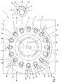
- Forming device 1 shown is designed for a processing of hollow bodies, in particular aluminum cans, in a step-by-step forming process.
- the forming device 1 comprises a machine frame 2 on which, by way of example, a workpiece rotary table 3 is rotatably mounted and a tool carrier 4 is mounted in a linearly movable manner, as indicated by the corresponding arrows in FIG FIG. 1 is indicated.
- the workpiece rotary table 3 is by means of a in the FIG. 1 Drive device not shown in a stepwise rotational movement, which is also referred to as a rotary step movement, about an axis of rotation 5 movable.
- the drive device and the workpiece rotary table 3 are preferably matched to one another in such a way that the rotary step movement always takes place with the same step width, in particular with the same angle about the axis of rotation 5.
- a plurality of workpiece holders 6 are arranged, preferably in the same angular pitch about the axis of rotation 5, which are adapted to receive hollow bodies 7.
- the in the FIG. 1 not shown, received in the machine frame 2 drive device is also designed to provide a cyclic linear movement of the tool carrier 4.
- the tool carrier 4 is mounted linearly movable on a support tube 8 and can perform an oscillating lifting movement relative to the workpiece rotary table 3.
- On the tool carrier 4 a plurality of tool holder 9 are arranged, which are arranged at the same angular pitch about the axis of rotation 5 as the workpiece holder 6 on the workpiece rotary table 3 and which are provided for receiving machining tools 10, in particular forming tools or cutting tools such as milling cutters.
- machining tools 10 With the help of the processing tools 10 can within the cyclic linear movement of the tool carrier Umformoperationen or other machining operations are performed on the received in the workpiece holders 6 hollow bodies.
- the workpiece holder 6 are arranged opposite to the tool holders 9 and can make the desired processing of the hollow body in the context of cyclic linear movement.
- FIG. 2 is the support tube 8, on which the tool carrier is guided linearly movable, visible in a sectional view.
- a non-illustrated coupling carriage is guided along a perpendicular to the plane of the FIG. 2 aligned movement axis can be moved linearly.
- the coupling carriage is coupled to a connecting rod 11.
- the connecting rod 11 is coupled to a double eccentric assembly 12 which can be rotated by a drive means 15 about an axis of rotation 13 to produce a combined rotational and translational motion from a pure rotational movement which is transmitted to the connecting rod 11.
- the connecting rod 11 moves the coupling carriage in a cyclic linear movement, which is transmitted to the tool carrier 4.
- Each of the workpiece holder 6 comprises an integrated clamping device 17, which is adapted to narrow a, for example, cylindrically shaped recess 16 in the workpiece holder 6 at least partially in the radial direction and thus apply the clamping force required for clamping the hollow body 7.
- each of the workpiece holders 6 is assigned, by way of example, an actuating lever 18, which is mounted pivotably on the workpiece holder 6 by means of a pivot bearing 26 and which is provided for actuating a control pin 19 provided by way of example.
- the control pin 19 is associated with the tensioning device 17 and can act, for example, on a fluid piston, not shown, of the tensioning device 17, which is provided, for example, for pressurizing a fluid contained in the tensioning device 17, in particular a hydraulic fluid.
- the actuating lever 18 has, by way of example, on a surface facing away from the workpiece holder 6, a cam extension 20 which is provided for engagement with control elements described in more detail below.
- a spring device 21 is arranged, which may be formed, for example, as a compression spring, in particular as a coil spring or cup spring stack.
- the spring device 21 exerts, for example, a compressive force on the associated end region of the actuating lever 18.
- the pressure force is dimensioned such that the tensioning device 17 is brought into a tensioned preferred position without external influences. This ensures that, without an external influence on the workpiece holder 6, in particular on the actuating lever 18, the clamping device 17 reliably fixes the hollow body 7 in the workpiece holder 6.
- an actuating movement directed inwardly at least almost in the radial direction is introduced on the actuating lever 18 by way of example.
- This adjusting movement can be introduced in a first embodiment of an actuating means as a pure linear movement of the actuating lever 18.
- a fluidically or electrically operated linear actuator in particular a fluid cylinder or an electric linear direct drive, can be used.
- the first adjusting means 22 and the second adjusting means 23 each formed as a linear actuator.
- a control rail 28 is arranged between the second adjusting means 23, which are associated with an unloading position 24 of the workpiece rotary table 3 and the first adjusting means 22, which are associated with a loading position 25 of the workpiece rotary table 3.
- the control rail 28 is formed so as to act on the cam extension 20 of the operating lever 18 and the operating lever 18 along a circular path of movement of the workpiece holder 6 between the second adjusting means 23 and the first adjusting means 22 forces in an operating position in which the clamping devices 17 are at least almost completely relaxed.
- the clamping device 17 is relaxed at the unloading position 24 by means of the second adjusting means 23 by controlling the actuating lever 18, whereby a removal or expulsion of the hollow body 7 from the workpiece holder 6 is made possible.
- the workpiece holder 6 which arrives at the loading position 25 in the course of the rotary step movements with a relaxed tensioning device 17 is initially held by the first adjusting means 22 in the illustrated relaxation position. Even before the initiation of a further rotary step movement on the workpiece rotary table 3, a hollow body 7 is first inserted into the workpiece holder 6. Subsequently, the first adjusting means 22 releases the actuating lever 18, so that it can return to its preferred position according to the bias of the spring means 21, in which the clamping device 17 is stretched and the hollow body 7 is fixed in the workpiece holder 6.
- an adjusting module 31 adjacent to the workpiece rotary table 3 is arranged is fixedly connected to the machine frame 2.
- the control module 31, which in the FIGS. 3 to 5 3, by way of example, comprises three further adjusting means 32, 33, 34 which are each designed to initiate at least proportionally linear positioning movements on the actuating levers 18 of the respectively temporarily opposing workpiece holders 6.
- Each of the adjusting means 32, 33, 34 has a rotatably mounted cam 35 which is rotatably mounted on the Positioning module 31 is mounted and can be offset from drive means not shown in a rotational movement.
- FIGS. 3 to 5 illustrated workpiece holder 6 forms an independent assembly, which can be exactly determined locally on the workpiece rotary table 3 by means not shown mounting means, in particular screwing, and positioning, in particular dowel pins.
- the workpiece holder 6 comprises a basic body 36, preferably made of metal, on which the actuating lever 18, the spring device 21 and a fluid displacement device 38 described in more detail below are arranged.
- the actuating lever 18 is pivotally mounted on the workpiece holder 6 by means of the pivot bearing 26, which comprises a hinge pin 44 rotatably mounted in the base body 36.
- the operating lever 18 includes a first lever portion 45 and a second lever portion 46, each extending from the pivot bearing 26 in opposite directions.
- the first lever portion 45 is located on the end of the control pin 19 which is associated with the fluid displacement means 38.
- the second lever portion 46 is fork-shaped at the end and carries between the fork legs a rotatably mounted drag roller 43rd
- the guide pin 48 is accommodated in a helical spring 47 and serves to transmit the spring force of the helical spring 47, which is embodied by way of example as a compression spring, onto the actuating lever 18.
- a cone ring 37 is arranged, which limits the recess 16 partially and the region tapers conically.
- an annular circumferential, flexible membrane 42 is arranged, which defines a shape described below in detail, formed in the base body 36 fluid channel 40 shape variable and is provided for a temporary and reversible narrowing of the free cross section of the recess 16 to a hollow body. 7 clamp.
- the fluid displacement device 38 comprises a cap mounted on the base body 36, screwed by way of example.
- the cap 49 serves as a linear guide for the control pin 19, which is coupled to a guide body 53 arranged below the cap 49.
- a fixed in the cap 49 slide bushing 56 is provided for the linear guide of the control pin 19, which passes through the cap 49.
- the cap 49 also serves to define the rotationally symmetrical rolling diaphragm 50, which is held sealingly on a radially outer edge region between the cap 49 and the base body 36.
- the guide body 53 is connected by means of a retaining bolt 57, which is screwed by way of example in the control pin 19, with the control pin 19, that the rolling diaphragm 50 seals the fluid channel 40 and the fluid received therein in a radially inner region relative to the surrounding atomic sphere.
- the guide body 53 serves to support the rolling diaphragm 50 in the case of a linear movement of the control pin 19 in the direction of the working space 59 formed in the main body 36, and thus to ensure that the rolling diaphragm 50 does so in the fluid channel 40, in particular in the working space 59, located, not shown fluid under pressure sets.
- the retaining bolt 56 has an annular guide collar 58, in which a first end region of a return spring 54 is accommodated.
- the second end region of the return spring 54 engages around a guide pin 55, which is screwed by way of example into the base body 36.
- the object of the return spring 54 is, without the presence of external influences on the fluid displacement device 38, the guide pin 19, the rolling diaphragm 50, the retaining pin 57 and the guide body 53 in the in FIG. 4 shown position in which there is at least almost no pressurization of the fluid and in which no clamping forces are exerted on a hollow body 7.
- the workpiece holder 6, the spring means 21 is formed such that a spring force is always exerted on the second lever portion 46, whereby a pressure force on the control pin 19 of the fluid displacement means 38 is applied.
- a pressure force attached to the control pin 19 rolling diaphragm 50 by means of the guide body 53 from the in FIG. 4 shown position moves in the direction of the working space 59, whereby a pressurization of the fluid occurs.
- the in FIG. 5 Membrane 42 which is shown in greater detail, is acted upon by the fluid pressure on an outer surface and thereby stretched. The membrane 42 performs in their expansion a combined radial and axial movement.
- the radial component of the movement in the radial direction is directed inwards and can cause the installation of the membrane 42 on an outer surface 60 of the hollow body 7.
- the axial component of the movement is parallel to a longitudinal axis 39 of the hollow body 7 and the recess 16 is aligned and acts from the mouth 41 of the recess 16 in the direction of a received in the recess 16 Bodenformst Formulaels 61.
- the direction of expansion of the diaphragm 42 is indicated by the directional arrows 51.
- the bottom forming ram 61 is provided to effect the concave impression in the bottom of the hollow body 7 upon application of a pressure force directed from the opening of the hollow body 7 in the direction of the bottom forming ram 61.
- the bottom mold tappet 61 is provided on a surface facing the hollow body 7 with a convex geometry, which is impressed into the hollow body 7 during the forming process.
- the bottom mold ram 61 can be used to eject the hollow body 7 from the workpiece holder 6.
- the Bodenformst Congressel 61 is moved relative to the base body 36 in the direction of the mouth 41 of the recess 16.
- the bottom forming ram 61 together with a support ring 63 described in more detail below, determines the bottom plane 79 of the hollow body 7, which can also be referred to as the contact surface of the hollow body 7.
- a support ring 63 is arranged circularly around the bottom mold tappet 61, which in turn has a circular peripheral, concave recess in which the edge region of the hollow body 7 can be received and supported.
- a pressure ring 62 which is conically formed on a surface 64 remote from the support ring 63.
- a conical outer surface 65 of the cone ring 37 and a circumferential retaining ring 66 which extends obliquely inwards in the direction of the bottom mold tappet 61 and exemplarily runs like a blade, formed with a U-shaped cross-section flexible membrane 42 is received.
- the membrane 42 defines in the radial direction inwardly a chamber associated with the fluid channel 40, which is bounded outwardly from the retaining ring 66 and in the FIG. 5 is not visible due to the lack of pressurization of the fluid.
- the membrane 42 lifts at least in places from the surface of the retaining ring 66 and expands in the radial direction inwardly and in the axial direction, as shown in FIG FIG. 5 down, out.
- the volume of the chamber corresponds to the volume of fluid that is displaced by the fluid displacement device 38 upon initiation of a linear adjusting movement on the control pin 19 in the working space 59.
- the retaining ring 66 is formed on a substantially cylindrically shaped channel ring 67, which is received in a cylindrical portion of the recess 16.
- the channel ring 67 has on its outer circumference a plurality of circumferential grooves 68, 69, 70.
- sealing rings 71 are added, which serve to seal the third groove 69 serving as part of the fluid channel 40 relative to the atmosphere.
- Through the circumferential groove 69 are introduced in the channel ring 66 and opening out on the outer surface of the diaphragm 42 oblique holes in communicating connection with the working space 59th
- the membrane 42 formed with a U-shaped cross-section has a first U-leg 73, a second U-leg 74 and a membrane ring 75 connecting the two legs 73 and 74.
- Each of the two legs 73, 74 is each end, radially outwardly provided with a circumferential bead, which is provided in each case for a positive reception between the outer surface 65 of the cone ring 37 and the retaining ring 66 and between the retaining ring 66 and the conical surface 64 of the pressure ring 62.
- the two legs 73, 74 are aligned almost parallel to each other, the diaphragm ring 75 is formed in the relaxed position of the membrane 42 is almost cylindrical, with its rotational symmetry axis coincides with the longitudinal axis 39.
- the retaining ring 66 in areas near the channel ring 67 each have circumferential, groove-like recesses 77, 78, which serve for a positive reception of the circumferential beads 76.
- the retaining ring 66, the conical ring 37 and the pressure ring 62 and the beads 76 of the membrane 42 are matched to one another such that the membrane 42 is wedged both edge positive and non-positive, whereby a secure and tight fixing of the membrane 42 is ensured.
- the membrane 42 thus at least partially seals off the fluid channel 40 from the atmosphere and thereby forms the wall section of the recess 16 that is adjustable in its geometry.
- a distance denoted by 11 between the bottom plane 79 and a lower range limit of a contact area between the membrane 42 and the hollow body 7 is spaced less than 5mm from the ground plane.
- a distance between the lower range limit of the touch area and the upper limit of the range is also less than 5 mm.
- the hollow body 7 is stretched measured from the ground plane 79 in an annular region, is about 4 mm wide and about 4 mm from the ground plane 79 is spaced.
- the retaining ring 66, the cone ring 37 and the pressure ring 62 together with the membrane 42 received thereon form a separate assembly which can be mounted independently of the base body 36 and tested for leaks. In a later assembly step, this assembly is only to be provided with the sealing rings 71 and inserted into the recess 16 of the workpiece holder 6. Due to the circumferential groove 69, no rotational alignment of the assembly relative to the base body 36 must be made. Rather, the communicating connection between the fluid channel 40 and the oblique bores 72 results solely from the insertion of the assembly into the recess 16.
- the flow chart shown is an example of the processes taking place during the processing of the hollow body 7.
- the time t [s] is plotted on the abscissa of the flow chart, the path s [m] is plotted on the ordinate.
- the cyclic linear movement can be represented for example as a sinusoidal linear oscillation of the tool carrier 4 and is denoted by the letter L.
- the cyclic linear motion is repeated within a time interval designated to.
- the rotational step movement which is denoted by the letter D, can be represented by way of example as a sequence of sinusoidal halves, which are temporally spaced from each other.
- the rotational step movement takes place in each case within a time interval designated with t1.
- the cyclic linear movement and the rotational step movement are coordinated such that the workpiece rotary table 3 rests while the machining tools 10 are in engagement with the hollow bodies 7.
- the intervention period is designated t2.
- the phase curve S3 for the linear adjusting movement of the third adjusting means 32 is selected such that the clamping device 17 of the oppositely disposed workpiece holder 6 is brought from the fully locked preferred position to a fully unlocked unlocking position and then back to the fully locked preferred position.
- the hollow body 7 can thus be pushed into the workpiece holder 6 after a bottom forming process, in which the contact of the hollow body bottom with a contact surface in the workpiece holder 6 is lost, and thus returned to surface contact with the workpiece holder 6.
- the phase curve S4 for the linear adjusting movement of the fourth adjusting means 33 is selected such that the clamping device 17 of the oppositely disposed workpiece holder 6 from the fully locked preferred position over a short period of time, preferably less than 15 percent corresponds to the cycle time of the cyclic linear movement is brought into a partially unlocked unlocking position and then back to the fully locked preferred position.
- the hollow body 7 can thereby be aligned correctly again relative to the workpiece holder 6 after a machining operation with machining forces acting asymmetrically on the hollow body 7.
- the phase curve S5 for the linear actuating movement of the fifth actuating means 34 is selected such that the clamping device 17 of the oppositely disposed workpiece holder 6 from the fully locked preferred position over a longer period of time, which corresponds to nearly 25 percent of the cycle time of the cyclic linear motion, in a partially unlocked unlocking position and then returned to the fully locked preferred position.
- the hollow body 7 can thus be rotated into a correct rotational position by means of a rotary tool mounted on the tool carrier 4 after a detection process in which the rotational position of the hollow body 7 has been determined about its longitudinal axis.
Landscapes
- Engineering & Computer Science (AREA)
- Mechanical Engineering (AREA)
- Jigs For Machine Tools (AREA)
- Shaping Metal By Deep-Drawing, Or The Like (AREA)
- Machine Tool Units (AREA)
Claims (15)
- Dispositif de formage pour des corps creux (7) en forme de coupe avec un bâti de machine (2), un dispositif d'entraînement (15), une table ronde porte-pièce (3) pour la réception de supports de pièce (6) qui sont réalisés pour la fixation de corps creux (7), et avec un porte-outil (4) pour la réception d'outils d'usinage (10), la table ronde porte-pièce (3) et le support d'outil (4) étant en regard l'un de l'autre et pouvant tourner autour d'un axe de rotation (5) l'un par rapport à l'autre ainsi que pouvant être déplacés linéairement l'un par rapport à l'autre le long de l'axe de rotation (5), le dispositif d'entraînement (15) étant réalisé pour la mise à disposition d'un mouvement de rotation à pas et d'un mouvement linéaire cyclique entre la table ronde porte-pièce (3) et le porte-outil (4) afin de permettre un formage des corps creux (7) à l'aide des outils d'usinage (10) dans plusieurs étapes d'usinage consécutives et le support de pièce (6) présentant un évidement (16) pour la réception d'un corps creux (7) et une section de paroi (42) qui délimite par endroits l'évidement (16) présentant une géométrie réglable réalisée pour le rétrécissement de la section transversale de l'évidement (16) afin de permettre une fixation du corps creux (7) sur le support de pièce (6), caractérisé en ce que la section de paroi (42) à la géométrie réglable est formée par une membrane flexible qui délimite par endroits un canal fluidique (40) réalisé dans le support de pièce (6).
- Dispositif de formage selon la revendication 1, caractérisé en ce qu'un dispositif de déplacement fluidique (38) logé de préférence de manière mobile linéairement, est disposé dans le canal fluidique (40), lequel dispositif est réalisé pour influencer une pression fluidique dans le canal fluidique (40) afin de pouvoir provoquer une modification de forme de la membrane flexible (42).
- Dispositif de formage selon la revendication 2, caractérisé en ce que le dispositif de déplacement fluidique (38) présente un piston de travail rigide, logé de manière mobile linéairement ou une membrane de travail (50) flexible, réalisée en particulier comme une membrane de roulement, serrée de manière étanche d'un coté.
- Dispositif de formage selon la revendication 2 ou 3, caractérisé en ce qu'un moyen de précontraint (21) est associé au dispositif de déplacement fluidique (38) le moyen de précontrainte comporte de préférence un moyen de ressort et qui est réalisé pour le réglage du dispositif de déplacement fluidique (38) dans une position d'avancement, de préférence dans une position de compression.
- Dispositif de formage selon la revendication 4, caractérisé en ce que le dispositif de déplacement fluidique (38) comporte un levier d'actionnement (18) logé de manière mobile en pivotement et est réalisé pour le couplage d'un coulisseau de travail (19) relié en action au piston de travail ou à la membrane de travail (50) avec les moyens de précontrainte (21) et/ou pour l'introduction d'un mouvement de réglage extérieur sur le coulisseau de travail (19).
- Dispositif de formage selon l'une quelconque des revendications précédentes, caractérisé en ce que la membrane flexible (42) est réalisée en forme d'anneau.
- Dispositif de formage selon l'une quelconque des revendications précédentes, caractérisé en ce que la membrane flexible (42) présente, dans un plan de section transversale qui comporte un axe longitudinal (39) de l'évidement (16), une section transversale en U ouverte dans la direction radiale vers l'extérieur.
- Dispositif de formage selon l'une quelconque des revendications précédentes, caractérisé en ce que la membrane flexible (42) est réalisée de telle manière qu'une zone de surface intérieure délimitant par endroits l'évidement de la membrane flexible (42) réalise, lors d'une mise sous pression du canal fluidique (40), un mouvement qui présente une composante de mouvement dirigée radialement vers l'intérieur et une composante de mouvement dirigée parallèlement à l'axe longitudinal (39) de l'évidement (16), en regard en particulier de l'ouverture d'embouchure (41).
- Dispositif de formage selon la revendication 8, caractérisé en ce que la membrane flexible (42) est réalisée de telle manière que les deux composantes de mouvement orientées perpendiculairement présentent au moins presque la même grandeur.
- Dispositif de formage selon la revendication 8 ou 9, caractérisé en ce qu'au moins une branche (73, 74) de la section transversale en U de la membrane flexible (40) forme un angle aigu, de préférence un angle inférieur à 80 degrés, de manière particulièrement préférée un angle inférieur à 70 degrés, en particulier un angle inférieur à 60 degrés avec l'axe longitudinal (39) de l'évidement (16).
- Dispositif de formage selon la revendication 8, 9 ou 10, caractérisé en ce que les deux branches (73, 74) de la section transversale en U de la membrane flexible (42) sont orientées au moins sensiblement parallèlement l'une à l'autre.
- Dispositif de formage selon l'une quelconque des revendications 7 à 11, caractérisé en ce qu'au moins une branche (73, 74) de la section transversale en U de la membrane flexible (42) dans une zone périphérique extérieure radiale présente un bourrelet (76) périphérique réalisé pour une fixation étanche dans le support de pièce (6).
- Dispositif de formage selon l'une quelconque des revendications précédentes, caractérisé en ce qu'un anneau conique (37) est disposé entre la membrane flexible (42) et une ouverture d'embouchure (41) de l'évidement (16), dont la surface intérieure conique (52) délimite par endroits l'évidement (16) et se rétrécit au fur et à mesure qu'elle s'éloigne de l'ouverture d'embouchure (41).
- Dispositif de formage selon l'une quelconque des revendications précédentes, caractérisé en ce que la membrane flexible (42) pour un contact avec le corps creux (7) est réalisée dans une zone annulaire qui présente une largeur de moins de 20 mm, de préférence moins de 15 mm, de manière particulièrement préférée moins de 10 mm, en particulier moins de 5 mm et qui occupe une distance par rapport à un plan de base (79) du corps creux (7) qui est déterminé par l'évidement (16), de moins de 20 mm, de préférence moins de 15 mm, de manière particulièrement préférée moins de 10 mm, en particulier moins de 5 mm.
- Dispositif de formage selon l'une quelconque des revendications précédentes, caractérisé en ce qu'un premier moyen de position (22) est associé à la table ronde porte-pièce (3) sur une position de verrouillage (25) pour l'introduction d'un mouvement de verrouillage sur le support de pièce (6) respectif et/ou un deuxième moyen de position (23) sur une position de déverrouillage pour l'introduction d'un mouvement de déverrouillage ainsi qu'un troisième moyen de position (32) sur une position d'usinage pour l'introduction d'un mouvement de réglage pour le déverrouillage au moins partiel et le verrouillage consécutif du corps creux (7) pendant un cycle du mouvement linéaire cyclique sur le support de pièce respectif (6).
Priority Applications (3)
| Application Number | Priority Date | Filing Date | Title |
|---|---|---|---|
| EP10002466.0A EP2364792B1 (fr) | 2010-03-10 | 2010-03-10 | Dispositif de formage |
| ES10002466.0T ES2468440T3 (es) | 2010-03-10 | 2010-03-10 | Instalación de transformación |
| US13/042,809 US8584502B2 (en) | 2010-03-10 | 2011-03-08 | Forming device |
Applications Claiming Priority (1)
| Application Number | Priority Date | Filing Date | Title |
|---|---|---|---|
| EP10002466.0A EP2364792B1 (fr) | 2010-03-10 | 2010-03-10 | Dispositif de formage |
Publications (2)
| Publication Number | Publication Date |
|---|---|
| EP2364792A1 EP2364792A1 (fr) | 2011-09-14 |
| EP2364792B1 true EP2364792B1 (fr) | 2014-03-05 |
Family
ID=42647457
Family Applications (1)
| Application Number | Title | Priority Date | Filing Date |
|---|---|---|---|
| EP10002466.0A Active EP2364792B1 (fr) | 2010-03-10 | 2010-03-10 | Dispositif de formage |
Country Status (3)
| Country | Link |
|---|---|
| US (1) | US8584502B2 (fr) |
| EP (1) | EP2364792B1 (fr) |
| ES (1) | ES2468440T3 (fr) |
Families Citing this family (4)
| Publication number | Priority date | Publication date | Assignee | Title |
|---|---|---|---|---|
| ITVR20110229A1 (it) | 2011-12-22 | 2013-06-23 | Spl Soluzioni S R L | Dispositivo di presa per il bloccaggio di contenitori metallici cilindrici destinati alla lavorazione mediante macchine operatrici |
| DE102017105501A1 (de) * | 2016-05-27 | 2017-11-30 | Universal Can Corporation | Dosenumformmaschine |
| EP3957412A1 (fr) | 2020-08-20 | 2022-02-23 | HINTERKOPF GmbH | Dispositif de préhension, support de préhension et système de préhension |
| CN114850389B (zh) * | 2022-06-10 | 2024-08-13 | 嘉兴海缙五金科技股份有限公司 | 一种螺母生产用冷镦装置 |
Family Cites Families (6)
| Publication number | Priority date | Publication date | Assignee | Title |
|---|---|---|---|---|
| US3797429A (en) * | 1973-02-22 | 1974-03-19 | United Can Co | Method and apparatus for necking and flanging can bodies |
| DE3779290D1 (de) | 1987-01-21 | 1992-06-25 | Frattini Costr Mecc | Maschine zum formen von konus und flansch an spruehdosen und dergleichen. |
| US6302364B1 (en) * | 1998-11-04 | 2001-10-16 | Visteon Global Technologies, Inc. | Pneumatic container holder |
| AR027371A1 (es) * | 2000-02-10 | 2003-03-26 | Envases Uk Ltd | Deformacion de cuerpos de pared delgada |
| WO2006043347A1 (fr) * | 2004-10-20 | 2006-04-27 | Universal Can Corporation | Procede de fabrication de canettes |
| US8096156B2 (en) * | 2006-12-22 | 2012-01-17 | Crown Packaging Technology, Inc. | Forming of metal container bodies |
-
2010
- 2010-03-10 ES ES10002466.0T patent/ES2468440T3/es active Active
- 2010-03-10 EP EP10002466.0A patent/EP2364792B1/fr active Active
-
2011
- 2011-03-08 US US13/042,809 patent/US8584502B2/en active Active
Also Published As
| Publication number | Publication date |
|---|---|
| ES2468440T3 (es) | 2014-06-16 |
| US20110219842A1 (en) | 2011-09-15 |
| US8584502B2 (en) | 2013-11-19 |
| EP2364792A1 (fr) | 2011-09-14 |
Similar Documents
| Publication | Publication Date | Title |
|---|---|---|
| DE2924707C2 (fr) | ||
| EP2676756A1 (fr) | Mandrin de puissance | |
| DE3443217C2 (fr) | ||
| EP3178579B1 (fr) | Procédé de fabrication d'une tube de chambre de combustion pur une système de retenue dans un véhicule automobile et dispositif permettant la mise en uvre du procédé | |
| DE102016111616B4 (de) | Vorrichtung und Verfahren zum Setzen eines Fügeelements an einem Werkstück oder zum Durchsetzfügen des Werkstücks | |
| EP3957412A1 (fr) | Dispositif de préhension, support de préhension et système de préhension | |
| EP2364792A1 (fr) | Dispositif de formage | |
| EP1738864A2 (fr) | Dispositif de serrage | |
| DE19733477C2 (de) | Verfahren zum Herstellen eines mit einem Fügeteil verbundenen von einer Ausgangsform mittels Innenhochdruck in eine Endform umgeformten Hohlprofiles sowie Vorrichtung zur Durchführung des Verfahrens | |
| DE10117485B4 (de) | Spanneinrichtung | |
| EP2076342B1 (fr) | Dispositif de déformation sous haute pression intérieure | |
| EP2873512B1 (fr) | Dispositif de poinçonnage et de soudage de pièces en matière plastique | |
| DE102015113583A1 (de) | Positioniereinrichtung | |
| EP1652615B1 (fr) | Dispositif de fixation pour une installation de soudage laser avec des supports activés chacun par un fluide hydraulique sous pression | |
| WO2007112720A1 (fr) | Procédé et dispositif outil de formage | |
| WO2017036610A1 (fr) | Tête d'étanchéité, dispositif et procédé de production de tubes bimétalliques | |
| WO2004054738A1 (fr) | Dispositif d'assemblage orbital | |
| DE102017106356B4 (de) | Niederhaltervorrichtung für eine Ziehvorrichtung zur Herstellung von hohlzylindrischen Körpern | |
| DE102015119177A1 (de) | Spannvorrichtung und Verfahren zum Spannen eines Wekstücks | |
| EP1413733B1 (fr) | Dispositif d'étanchéité | |
| EP2759376B1 (fr) | Dispositif avec dispositif de serrage d'un composant moteur avec ouverture de palier | |
| DE10061635B4 (de) | Umform- und Fügeverfahren von zumindest zwei Bauteilen und Vorrichtung | |
| WO2015170305A1 (fr) | Outil de tournage-brochage de pièces | |
| EP1752233B1 (fr) | Presse de tuyaux souples pour la production des conduits hydrauliques | |
| EP1984132B1 (fr) | Pince d'usinage hydraulique |
Legal Events
| Date | Code | Title | Description |
|---|---|---|---|
| PUAI | Public reference made under article 153(3) epc to a published international application that has entered the european phase |
Free format text: ORIGINAL CODE: 0009012 |
|
| 17P | Request for examination filed |
Effective date: 20110112 |
|
| AK | Designated contracting states |
Kind code of ref document: A1 Designated state(s): AT BE BG CH CY CZ DE DK EE ES FI FR GB GR HR HU IE IS IT LI LT LU LV MC MK MT NL NO PL PT RO SE SI SK SM TR |
|
| AX | Request for extension of the european patent |
Extension state: AL BA ME RS |
|
| GRAP | Despatch of communication of intention to grant a patent |
Free format text: ORIGINAL CODE: EPIDOSNIGR1 |
|
| INTG | Intention to grant announced |
Effective date: 20131007 |
|
| GRAS | Grant fee paid |
Free format text: ORIGINAL CODE: EPIDOSNIGR3 |
|
| GRAA | (expected) grant |
Free format text: ORIGINAL CODE: 0009210 |
|
| AK | Designated contracting states |
Kind code of ref document: B1 Designated state(s): AT BE BG CH CY CZ DE DK EE ES FI FR GB GR HR HU IE IS IT LI LT LU LV MC MK MT NL NO PL PT RO SE SI SK SM TR |
|
| REG | Reference to a national code |
Ref country code: GB Ref legal event code: FG4D Free format text: NOT ENGLISH |
|
| REG | Reference to a national code |
Ref country code: CH Ref legal event code: EP |
|
| REG | Reference to a national code |
Ref country code: AT Ref legal event code: REF Ref document number: 654483 Country of ref document: AT Kind code of ref document: T Effective date: 20140315 |
|
| REG | Reference to a national code |
Ref country code: CH Ref legal event code: NV Representative=s name: TROESCH SCHEIDEGGER WERNER AG, CH |
|
| REG | Reference to a national code |
Ref country code: IE Ref legal event code: FG4D Free format text: LANGUAGE OF EP DOCUMENT: GERMAN |
|
| REG | Reference to a national code |
Ref country code: DE Ref legal event code: R096 Ref document number: 502010006225 Country of ref document: DE Effective date: 20140424 |
|
| REG | Reference to a national code |
Ref country code: ES Ref legal event code: FG2A Ref document number: 2468440 Country of ref document: ES Kind code of ref document: T3 Effective date: 20140616 |
|
| REG | Reference to a national code |
Ref country code: NL Ref legal event code: VDEP Effective date: 20140305 |
|
| PG25 | Lapsed in a contracting state [announced via postgrant information from national office to epo] |
Ref country code: LT Free format text: LAPSE BECAUSE OF FAILURE TO SUBMIT A TRANSLATION OF THE DESCRIPTION OR TO PAY THE FEE WITHIN THE PRESCRIBED TIME-LIMIT Effective date: 20140305 Ref country code: NO Free format text: LAPSE BECAUSE OF FAILURE TO SUBMIT A TRANSLATION OF THE DESCRIPTION OR TO PAY THE FEE WITHIN THE PRESCRIBED TIME-LIMIT Effective date: 20140605 |
|
| REG | Reference to a national code |
Ref country code: LT Ref legal event code: MG4D |
|
| PG25 | Lapsed in a contracting state [announced via postgrant information from national office to epo] |
Ref country code: SE Free format text: LAPSE BECAUSE OF FAILURE TO SUBMIT A TRANSLATION OF THE DESCRIPTION OR TO PAY THE FEE WITHIN THE PRESCRIBED TIME-LIMIT Effective date: 20140305 Ref country code: CY Free format text: LAPSE BECAUSE OF FAILURE TO SUBMIT A TRANSLATION OF THE DESCRIPTION OR TO PAY THE FEE WITHIN THE PRESCRIBED TIME-LIMIT Effective date: 20140305 Ref country code: FI Free format text: LAPSE BECAUSE OF FAILURE TO SUBMIT A TRANSLATION OF THE DESCRIPTION OR TO PAY THE FEE WITHIN THE PRESCRIBED TIME-LIMIT Effective date: 20140305 |
|
| PG25 | Lapsed in a contracting state [announced via postgrant information from national office to epo] |
Ref country code: LV Free format text: LAPSE BECAUSE OF FAILURE TO SUBMIT A TRANSLATION OF THE DESCRIPTION OR TO PAY THE FEE WITHIN THE PRESCRIBED TIME-LIMIT Effective date: 20140305 Ref country code: HR Free format text: LAPSE BECAUSE OF FAILURE TO SUBMIT A TRANSLATION OF THE DESCRIPTION OR TO PAY THE FEE WITHIN THE PRESCRIBED TIME-LIMIT Effective date: 20140305 |
|
| PG25 | Lapsed in a contracting state [announced via postgrant information from national office to epo] |
Ref country code: RO Free format text: LAPSE BECAUSE OF FAILURE TO SUBMIT A TRANSLATION OF THE DESCRIPTION OR TO PAY THE FEE WITHIN THE PRESCRIBED TIME-LIMIT Effective date: 20140305 Ref country code: NL Free format text: LAPSE BECAUSE OF FAILURE TO SUBMIT A TRANSLATION OF THE DESCRIPTION OR TO PAY THE FEE WITHIN THE PRESCRIBED TIME-LIMIT Effective date: 20140305 Ref country code: IS Free format text: LAPSE BECAUSE OF FAILURE TO SUBMIT A TRANSLATION OF THE DESCRIPTION OR TO PAY THE FEE WITHIN THE PRESCRIBED TIME-LIMIT Effective date: 20140705 Ref country code: BG Free format text: LAPSE BECAUSE OF FAILURE TO SUBMIT A TRANSLATION OF THE DESCRIPTION OR TO PAY THE FEE WITHIN THE PRESCRIBED TIME-LIMIT Effective date: 20140605 Ref country code: EE Free format text: LAPSE BECAUSE OF FAILURE TO SUBMIT A TRANSLATION OF THE DESCRIPTION OR TO PAY THE FEE WITHIN THE PRESCRIBED TIME-LIMIT Effective date: 20140305 |
|
| PG25 | Lapsed in a contracting state [announced via postgrant information from national office to epo] |
Ref country code: PL Free format text: LAPSE BECAUSE OF FAILURE TO SUBMIT A TRANSLATION OF THE DESCRIPTION OR TO PAY THE FEE WITHIN THE PRESCRIBED TIME-LIMIT Effective date: 20140305 Ref country code: SK Free format text: LAPSE BECAUSE OF FAILURE TO SUBMIT A TRANSLATION OF THE DESCRIPTION OR TO PAY THE FEE WITHIN THE PRESCRIBED TIME-LIMIT Effective date: 20140305 |
|
| REG | Reference to a national code |
Ref country code: DE Ref legal event code: R097 Ref document number: 502010006225 Country of ref document: DE |
|
| PG25 | Lapsed in a contracting state [announced via postgrant information from national office to epo] |
Ref country code: PT Free format text: LAPSE BECAUSE OF FAILURE TO SUBMIT A TRANSLATION OF THE DESCRIPTION OR TO PAY THE FEE WITHIN THE PRESCRIBED TIME-LIMIT Effective date: 20140707 |
|
| REG | Reference to a national code |
Ref country code: IE Ref legal event code: MM4A |
|
| PLBE | No opposition filed within time limit |
Free format text: ORIGINAL CODE: 0009261 |
|
| STAA | Information on the status of an ep patent application or granted ep patent |
Free format text: STATUS: NO OPPOSITION FILED WITHIN TIME LIMIT |
|
| PG25 | Lapsed in a contracting state [announced via postgrant information from national office to epo] |
Ref country code: DK Free format text: LAPSE BECAUSE OF FAILURE TO SUBMIT A TRANSLATION OF THE DESCRIPTION OR TO PAY THE FEE WITHIN THE PRESCRIBED TIME-LIMIT Effective date: 20140305 Ref country code: MC Free format text: LAPSE BECAUSE OF FAILURE TO SUBMIT A TRANSLATION OF THE DESCRIPTION OR TO PAY THE FEE WITHIN THE PRESCRIBED TIME-LIMIT Effective date: 20140305 Ref country code: IE Free format text: LAPSE BECAUSE OF NON-PAYMENT OF DUE FEES Effective date: 20140310 |
|
| 26N | No opposition filed |
Effective date: 20141208 |
|
| REG | Reference to a national code |
Ref country code: DE Ref legal event code: R097 Ref document number: 502010006225 Country of ref document: DE Effective date: 20141208 |
|
| PG25 | Lapsed in a contracting state [announced via postgrant information from national office to epo] |
Ref country code: SI Free format text: LAPSE BECAUSE OF FAILURE TO SUBMIT A TRANSLATION OF THE DESCRIPTION OR TO PAY THE FEE WITHIN THE PRESCRIBED TIME-LIMIT Effective date: 20140305 |
|
| PG25 | Lapsed in a contracting state [announced via postgrant information from national office to epo] |
Ref country code: MT Free format text: LAPSE BECAUSE OF FAILURE TO SUBMIT A TRANSLATION OF THE DESCRIPTION OR TO PAY THE FEE WITHIN THE PRESCRIBED TIME-LIMIT Effective date: 20140305 |
|
| REG | Reference to a national code |
Ref country code: FR Ref legal event code: PLFP Year of fee payment: 7 |
|
| PG25 | Lapsed in a contracting state [announced via postgrant information from national office to epo] |
Ref country code: SM Free format text: LAPSE BECAUSE OF FAILURE TO SUBMIT A TRANSLATION OF THE DESCRIPTION OR TO PAY THE FEE WITHIN THE PRESCRIBED TIME-LIMIT Effective date: 20140305 |
|
| REG | Reference to a national code |
Ref country code: AT Ref legal event code: MM01 Ref document number: 654483 Country of ref document: AT Kind code of ref document: T Effective date: 20150310 |
|
| PG25 | Lapsed in a contracting state [announced via postgrant information from national office to epo] |
Ref country code: GR Free format text: LAPSE BECAUSE OF FAILURE TO SUBMIT A TRANSLATION OF THE DESCRIPTION OR TO PAY THE FEE WITHIN THE PRESCRIBED TIME-LIMIT Effective date: 20140606 |
|
| PG25 | Lapsed in a contracting state [announced via postgrant information from national office to epo] |
Ref country code: LU Free format text: LAPSE BECAUSE OF NON-PAYMENT OF DUE FEES Effective date: 20140310 Ref country code: BE Free format text: LAPSE BECAUSE OF FAILURE TO SUBMIT A TRANSLATION OF THE DESCRIPTION OR TO PAY THE FEE WITHIN THE PRESCRIBED TIME-LIMIT Effective date: 20140331 Ref country code: HU Free format text: LAPSE BECAUSE OF FAILURE TO SUBMIT A TRANSLATION OF THE DESCRIPTION OR TO PAY THE FEE WITHIN THE PRESCRIBED TIME-LIMIT; INVALID AB INITIO Effective date: 20100310 Ref country code: TR Free format text: LAPSE BECAUSE OF FAILURE TO SUBMIT A TRANSLATION OF THE DESCRIPTION OR TO PAY THE FEE WITHIN THE PRESCRIBED TIME-LIMIT Effective date: 20140305 |
|
| PG25 | Lapsed in a contracting state [announced via postgrant information from national office to epo] |
Ref country code: AT Free format text: LAPSE BECAUSE OF NON-PAYMENT OF DUE FEES Effective date: 20150310 |
|
| REG | Reference to a national code |
Ref country code: FR Ref legal event code: PLFP Year of fee payment: 8 |
|
| REG | Reference to a national code |
Ref country code: FR Ref legal event code: PLFP Year of fee payment: 9 |
|
| PG25 | Lapsed in a contracting state [announced via postgrant information from national office to epo] |
Ref country code: MK Free format text: LAPSE BECAUSE OF FAILURE TO SUBMIT A TRANSLATION OF THE DESCRIPTION OR TO PAY THE FEE WITHIN THE PRESCRIBED TIME-LIMIT Effective date: 20140305 |
|
| P01 | Opt-out of the competence of the unified patent court (upc) registered |
Effective date: 20230530 |
|
| PGFP | Annual fee paid to national office [announced via postgrant information from national office to epo] |
Ref country code: ES Payment date: 20250416 Year of fee payment: 16 |
|
| PGFP | Annual fee paid to national office [announced via postgrant information from national office to epo] |
Ref country code: IT Payment date: 20250331 Year of fee payment: 16 |
|
| PGFP | Annual fee paid to national office [announced via postgrant information from national office to epo] |
Ref country code: CH Payment date: 20250401 Year of fee payment: 16 |
|
| REG | Reference to a national code |
Ref country code: CH Ref legal event code: U11 Free format text: ST27 STATUS EVENT CODE: U-0-0-U10-U11 (AS PROVIDED BY THE NATIONAL OFFICE) Effective date: 20260401 |
|
| PGFP | Annual fee paid to national office [announced via postgrant information from national office to epo] |
Ref country code: GB Payment date: 20260317 Year of fee payment: 17 |
|
| PGFP | Annual fee paid to national office [announced via postgrant information from national office to epo] |
Ref country code: DE Payment date: 20260205 Year of fee payment: 17 |
|
| PGFP | Annual fee paid to national office [announced via postgrant information from national office to epo] |
Ref country code: FR Payment date: 20260325 Year of fee payment: 17 |
|
| PGFP | Annual fee paid to national office [announced via postgrant information from national office to epo] |
Ref country code: CZ Payment date: 20260225 Year of fee payment: 17 |