EP2365191A2 - Belastbare Struktur für eine Gasturbine - Google Patents
Belastbare Struktur für eine Gasturbine Download PDFInfo
- Publication number
- EP2365191A2 EP2365191A2 EP11250252A EP11250252A EP2365191A2 EP 2365191 A2 EP2365191 A2 EP 2365191A2 EP 11250252 A EP11250252 A EP 11250252A EP 11250252 A EP11250252 A EP 11250252A EP 2365191 A2 EP2365191 A2 EP 2365191A2
- Authority
- EP
- European Patent Office
- Prior art keywords
- diameter ring
- strain relief
- assembly
- relief feature
- strut
- Prior art date
- Legal status (The legal status is an assumption and is not a legal conclusion. Google has not performed a legal analysis and makes no representation as to the accuracy of the status listed.)
- Granted
Links
Images


Classifications
-
- F—MECHANICAL ENGINEERING; LIGHTING; HEATING; WEAPONS; BLASTING
- F01—MACHINES OR ENGINES IN GENERAL; ENGINE PLANTS IN GENERAL; STEAM ENGINES
- F01D—NON-POSITIVE DISPLACEMENT MACHINES OR ENGINES, e.g. STEAM TURBINES
- F01D25/00—Component parts, details, or accessories, not provided for in, or of interest apart from, other groups
- F01D25/16—Arrangement of bearings; Supporting or mounting bearings in casings
- F01D25/162—Bearing supports
-
- F—MECHANICAL ENGINEERING; LIGHTING; HEATING; WEAPONS; BLASTING
- F05—INDEXING SCHEMES RELATING TO ENGINES OR PUMPS IN VARIOUS SUBCLASSES OF CLASSES F01-F04
- F05D—INDEXING SCHEME FOR ASPECTS RELATING TO NON-POSITIVE-DISPLACEMENT MACHINES OR ENGINES, GAS-TURBINES OR JET-PROPULSION PLANTS
- F05D2260/00—Function
- F05D2260/94—Functionality given by mechanical stress related aspects such as low cycle fatigue [LCF] of high cycle fatigue [HCF]
- F05D2260/941—Functionality given by mechanical stress related aspects such as low cycle fatigue [LCF] of high cycle fatigue [HCF] particularly aimed at mechanical or thermal stress reduction
Definitions
- the present application relates to gas turbine engines, and more particularly, to bound assemblies disposed along the gas flow path of gas turbine engines.
- working gases flow along a gas flow path, which in various sections of the engine can be defined by an inner case and an outer case.
- the inner case is disposed radially inward of the outer case with respect to the centreline of the gas turbine engine.
- Both cases are commonly comprised of a plurality of ring shaped structures that are assembled and connected axially to one another to form the housing/casing that defines the gas flow path.
- a plurality of airfoils comprising static vanes and rotor blades are disposed within the gas flow path along the compressor and turbine stages to extract mechanical work from the working gases.
- bound assemblies such as static ring/strut/ring assemblies are disposed in the gas flow path at various stages including in or adjacent the fan section, compressor section, turbine section, exhaust section, and diffuser.
- Ring/strut/ring assemblies can be thought of as bound assemblies because the strut is connected to both the inner case and the outer case.
- Bound assemblies are commonly used to provide structural support to one or both of the cases or to bearings which support the shafts that rotate within the engine.
- Bound assemblies such as struts are also used in some applications for aerodynamic and/or noise reduction purposes within the gas flow path.
- Gas turbine engines are continually undergoing changes with the goals of improving performance, decreasing size and weight for a given thrust rating, while reducing cost and enhancing durability and reparability.
- To improve performance it is typical to increase the operation temperature of the engine, since increased temperatures generally will translate into improved engine performance.
- increased temperatures the components disposed in and adjacent to the gas flow path are subjected to increased temperature gradients.
- the strut remains connected to both the inner case and outer case during thermal induced expansion, with the result being a thermal fight or "punch load” that typically causes high strains in or near the curved fillets that connect the cases with the struts.
- These high strains limit the number of thermal cycles the bound structure can be exposed to before experiencing cracks in or near the fillets.
- the cracks limit the useful service life of the bound structure.
- a bound assembly for a gas turbine engine includes an inner diameter ring, a strut, and an outer diameter ring.
- the inner diameter ring is disposed radially around a centreline of the gas turbine engine.
- the strut is connected to the inner diameter ring and extends radially outward therefrom to connect to the outer diameter ring.
- the inner diameter ring, strut and/or the outer diameter ring has a strain relief feature that is disposed adjacent to or at the connection between the strut and the inner diameter ring and/or the outer diameter ring.
- the strain relief feature lengthens the arc segment of fillet curvature. For a constant thermal punch load this results in a decreased maximum strain in the bound assembly.
- the present application describes a crenellated strain relief feature(s) for reducing maximum strain in bound assemblies that are subject to thermal gradients within gas turbine engines.
- the strain relief feature(s) reduces maximum strain in ring/strut/ring assemblies disposed adjacent to or along the gas flow path of a gas turbine engine. By reducing maximum strain, the strain relief feature improves the service life of the bound assemblies within gas turbine engines.
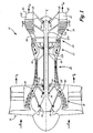
- FIG. 1 shows a schematic cross section of a gas turbine engine 10.
- Gas turbine engine 10 has anti-friction bearings 14 that support shafts 12A and 12B.
- Gas turbine engine 10 is defined around an engine centreline C L about which various engine sections rotate.
- gas turbine engine 10 includes a fan section 16, a low pressure compressor (LPC) section 18, a high pressure compressor (HPC) section 20, a combustor 22, a high pressure turbine section 24, and a low pressure turbine section 26.
- Working gases G w are defined by an inner case 28 and an outer case 30 to travel through the various sections 18, 20, 24 and 26 of gas turbine engine 10.
- Bearings 14, inner case 28, and/or outer case 30 are supported at various locations along gas turbine engine 10 by bound assemblies including turbine exhaust struts 32, a mid-turbine frame 34, and a diffuser case 36.
- Gas turbine engine 10 is illustrated as a high bypass ratio turbofan engine with a dual spool arrangement in which fan section 16 and LPC section 18 are connected to a low pressure turbine section 26 by various rotors and shaft 12A, and HPC section 20 is connected to high pressure turbine section 24 by second shaft 12B.
- gas turbine engines and in particular turbofan engines, is well-known in the art, and therefore, detailed discussion herein is unnecessary. It should be noted, however, that engine 10 is shown in FIG. 1 merely by way of example and not limitation. The present invention is also applicable to a variety of other gas turbine engine configurations, such as a turboprop engine, for example.
- Gas is pulled into fan section 16 by the rotation of the fan blades about the centreline axis C L .
- the gas is divided into streams of working gas G w (primary air) and bypass gas G B after passing the fan.
- the fan is rotated by low pressure turbine section 24 through shaft 12A to accelerate the bypass gas G B through fan section 16, thereby producing a significant portion of the thrust output of engine 10.
- the working gas G w is directed along a gas flow path that extends through engine 10.
- the working gas G w flows through LPC section 18 to HPC section 20 then to high pressure turbine section 24 and low pressure turbine section 26.
- the working gas G w is mixed with fuel and ignited in combustor 22 and is then directed into the turbine sections 24 and 26 where the mixture is successively expanded through alternating stages of airfoils comprising rotor blades and stator vanes to extract mechanical work therefrom.
- the gas flow path can be bounded by inner case 28 and outer case 30.
- bound assemblies include turbine exhaust struts 32, mid-turbine frame 34, and diffuser case 36. These bound assemblies provide structural support for bearings 14, inner case 28 and/or outer case 30 in various locations within turbine engine 10. Bound assemblies such as guide vanes can also serve non-structural purposes such as for aerodynamic improvement and/or noise reduction.
- turbine exhaust struts 32 are positioned rearward of low pressure turbine section 26 in gas flow path.
- the extremely hot working gas G w exhausted from low pressure turbine section 26 passes across turbine exhaust struts 32.
- Inner case 28, outer case 30, and turbine exhaust struts 32 are connected together as an assembly, commonly called a turbine exhaust case.
- Turbine exhaust struts 32 are used to support a rear bearing 14 and impart an axial direction to working air G w , thereby increasing the velocity of working gas G w to increase its momentum and generate more thrust.
- mid-turbine frame 34 is located between high pressure turbine section 24 and low pressure turbine section 26 and transfers load from bearings 14 and bearing support structures to inner case 28 and/or outer case 30.
- Diffuser case 36 includes struts connecting the diffuser (located between HPC 20 and combustor 22) to outer case 30. Diffuser case 36 can be used to support at least one bearing 14.
- FIG. 2 shows a perspective view of a bound assembly 38.
- Bound assembly 38 includes an inner diameter ring 40, struts 42 and an outer diameter ring 44.
- Outer diameter ring 44 includes leading edge flange 46L and trailing edge flange 46T.
- Bound assembly 38 also includes a plurality of strain relief features 48A and 48B.
- bound assembly 38 can comprise one of many turbine engine structures.
- Inner diameter ring 40 is disposed radially around the centreline C L of the gas turbine engine 10 ( FIG. 1 ).
- Inner diameter ring 40 can comprise a portion of or be disposed adjacent inner case 28 ( FIG. 1 ).
- Struts 42 connect to inner diameter ring 40 in a manner known in the art (e.g., welding, forging, casting and subsequent fabrication). It should be noted that strain relief features 48A are distinct from and should be disposed at a distance from welding joints.
- Struts 42 can be hollow or solid structures and extend radially outward from inner diameter ring 40 to connect to outer diameter ring 44 in a plurality of locations. Thus, outer diameter ring 44 is disposed radially outward of inner diameter ring 40.
- Strain relief features 48A are disposed along outer diameter ring 44 at connection between struts 42 and outer diameter ring 44.
- Outer diameter ring 44 extends axially forward and aft of struts with respect to the centreline C L and extends to leading edge flange 46L and trailing edge flange 46T.
- Leading edge flange 46L and trailing edge flange 46T are adapted to connect bound assembly 38 to adjacent structures or other bound assemblies 38 utilizing fasteners (not shown) or other means.
- Leading edge flange 46L is disposed downstream of trailing edge flange 46T (as defined by the direction of flow of the working gas G w ).
- Bound assemblies 38 can be connected together to form inner case 28 ( FIG. 1 ) and outer case 30 ( FIG. 1 ) such that the working gas G w flows past struts 42.
- FIG. 2A shows a partial section of bound assembly 38 from FIG. 2 .
- Bound assembly 38 includes strain relief feature 48A disposed adjacent to or at the connection between the strut 42 and inner diameter ring 40 and/or the outer diameter ring 44.
- strain relief feature 48A is a crenellation or ridge on outer diameter ring 44 that extends radially outward from an outer radial surface 58 of the outer diameter ring 44.
- Strain relief feature 48A extends around the entire connection between the strut 42 and outer diameter ring 44.
- strain relief feature 48A extends around the leading edge 52L of strut 42 and the trailing edge 52T of strut 42.
- strain relief feature 48A may be localized to adjacent leading edge 52L and/or trailing edge 52T only, or disposed adjacent other portions of connection. Thus, strain relief feature 48A would not extend entirely around the connection between the strut 42 and the inner diameter ring 40 and/or the outer diameter ring 44.
- FIG. 2B shows a sectional view of bound assembly 38 that extends through the outer diameter ring 44, inner diameter ring 40, and strut 42 along line B-B of FIG. 2A .
- the sectional view extends through strain relief feature 48A which is disposed adjacent a body 54 of strut 42 near or at a mouth 56 thereof.
- strain relief feature 48A is disposed at the connection between strut 42 and outer diameter ring 44 and strain relief feature 48B is disposed at the connection between strut 42 and inner diameter ring 40.
- strain relief feature 48A is curved in shape such that it comprises a ridge on outer diameter ring 44 that extends radially outward so as to create an offset from outer radial surface 58 thereof.
- strain relief feature 48A also creates a depression or trench that extends along an inner radial surface 60 of the outer diameter ring 44.
- Second strain relief feature 48B is located on inner diameter ring 40 adjacent strut 42 and is curved in shape so as to comprise a ridge on inner diameter ring 40. Strain relief feature 48B extends radially inward toward the centreline C L of engine 10 ( FIG. 1 ) so as to create an offset between an inner radial surface 62 and the second strain relief feature 48B.
- the curvature of second strain relief feature 48B creates a depression or trench that extends along an outer radial surface 64 of inner diameter ring 40.
- strain relief feature 48A and second strain relief feature 48B need not be of the same size or shape or extend around strut 42 to the same extent.
- strain relief feature 48A and/or 48B can be sized so as to extend beyond the boundary layer (a region characterized by low velocity flows which vary in direction with respect to the mainstream velocity according to local pressure gradients) into the mainstream of gas flow path.
- strain relief feature 48A and/or 48B can be sized so as not to extend beyond the boundary layer.
- strain relief feature 48A has arcuate inner and outer radii (only inner radii R are illustrated) and extends outward to create offset O a distance from outer radial surface 58.
- the distance of the offset O can vary.
- radii R lengthen the arc segment of fillet curvature and give strain relief feature 48A a continuous transition from one radius R to the next.
- the height of strain relief feature 48A (or depth of depression) relative to outer radial surface 58 of outer diameter ring 44 is dependant upon a cross sectional thickness T of outer diameter ring 44.
- the offset O distance can be one or two times that of thickness T of outer diameter ring 44 to reduce peak strain due to temperature gradients.
- the height or the depth of the strain relief feature(s) relative to a surface of inner diameter ring 40 or outer diameter ring 44 is dependant upon a cross sectional thickness of the inner diameter ring 40 or strut 42.
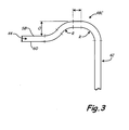
- FIG. 3 illustrates another embodiment of strain relief feature 48C.
- strain relief feature 48C can have an area with no radius (a flat area) between radii R.
- the geometry (cross sectional area, length, location relative to or within strut 42) of the strain relief features can be varied to reduce maximum strain of bound assembly 38 during operation.
- the geometry of the strain relief features can be optimized to design criteria to reduce maximum strain using commercially available finite element analysis tools such as software retailed by ANSYS, Inc. of Canonsburg, Pennsylvania.
- the strain relief feature lengthens the arc segment of fillet curvature.
- the strain relief feature reduces maximum strain by spreading the total thermally induced strain over a larger area than conventional fillets. Lower values of maximum strain allows for an increased number of thermal cycles before initiation of cracks and a longer service life for the bound assembly.
- FIGS. 4 and 4A show cross sections of bound assembly 38 with a strain relief feature 48D and a strain relief feature 48E disposed adjacent strut 42 and a strain relief feature 48F disposed in strut 42.
- Strain relief feature 48D is disposed at the connection between strut 42 and outer diameter ring 44 and has a sinusoidal cross section that creates ridges and a depression on outer radial surface 58 and depressions and a ridge on inner radial surface 60 of outer diameter ring 44.
- strain relief feature 48E is disposed at the connection between strut 42 and inner diameter ring 40 and has a sinusoidal cross section that creates ridges and a depression on inner radial surface 62 and depressions and a ridge on outer radial surface 64 of inner diameter ring 40.
- Strain relief feature 48F is positioned within the body 54 of strut 42 adjacent mouth 56 and strain relief feature 48D. Together, strain relief features 48D, 48E, and 48F reduce maximum strain in bound assembly 38. As discussed previously, the geometry of the strain relief features can be optimized to design criteria to reduce maximum strain using ANSYS.
Landscapes
- Engineering & Computer Science (AREA)
- Mechanical Engineering (AREA)
- General Engineering & Computer Science (AREA)
- Structures Of Non-Positive Displacement Pumps (AREA)
- Turbine Rotor Nozzle Sealing (AREA)
Applications Claiming Priority (1)
| Application Number | Priority Date | Filing Date | Title |
|---|---|---|---|
| US12/719,051 US8776533B2 (en) | 2010-03-08 | 2010-03-08 | Strain tolerant bound structure for a gas turbine engine |
Publications (3)
| Publication Number | Publication Date |
|---|---|
| EP2365191A2 true EP2365191A2 (de) | 2011-09-14 |
| EP2365191A3 EP2365191A3 (de) | 2014-09-24 |
| EP2365191B1 EP2365191B1 (de) | 2018-08-29 |
Family
ID=43858262
Family Applications (1)
| Application Number | Title | Priority Date | Filing Date |
|---|---|---|---|
| EP11250252.1A Active EP2365191B1 (de) | 2010-03-08 | 2011-03-04 | Belastbare Struktur für eine Gasturbine |
Country Status (2)
| Country | Link |
|---|---|
| US (1) | US8776533B2 (de) |
| EP (1) | EP2365191B1 (de) |
Cited By (5)
| Publication number | Priority date | Publication date | Assignee | Title |
|---|---|---|---|---|
| WO2015020767A1 (en) * | 2013-08-07 | 2015-02-12 | Siemens Energy, Inc. | Manufacturing method for exhaust diffuser shell with strut shield collar and joint flange |
| WO2015020751A1 (en) * | 2013-08-07 | 2015-02-12 | Siemens Energy, Inc. | Manufacturing method for strut shield collar of gas turbine exhaust diffuser |
| EP3456926A1 (de) * | 2017-09-15 | 2019-03-20 | Doosan Heavy Industries & Construction Co., Ltd | Gasturbine mit einer stützstruktur für ein lager |
| WO2019063635A1 (en) * | 2017-09-26 | 2019-04-04 | Gkn Aerospace Sweden Ab | EVIDENCE FOR CARTER EXTERIOR |
| EP3715585A1 (de) * | 2019-03-26 | 2020-09-30 | Doosan Heavy Industries & Construction Co., Ltd. | Strebenstruktur einer gasturbine sowie abgasdiffusor und gasturbine damit |
Families Citing this family (53)
| Publication number | Priority date | Publication date | Assignee | Title |
|---|---|---|---|---|
| US8484976B2 (en) * | 2008-06-12 | 2013-07-16 | Lockheed Martin Corporation | System, method and apparatus for fluidic effectors for enhanced fluid flow mixing |
| US8992173B2 (en) | 2011-11-04 | 2015-03-31 | United Technologies Corporation | Tie-rod nut including a nut flange with a plurality of mounting apertures |
| US9394915B2 (en) | 2012-06-04 | 2016-07-19 | United Technologies Corporation | Seal land for static structure of a gas turbine engine |
| BR122015003108B1 (pt) * | 2012-06-15 | 2023-05-09 | United Technologies Corporation | Motor de turbina a gás |
| US9303528B2 (en) | 2012-07-06 | 2016-04-05 | United Technologies Corporation | Mid-turbine frame thermal radiation shield |
| US9217371B2 (en) * | 2012-07-13 | 2015-12-22 | United Technologies Corporation | Mid-turbine frame with tensioned spokes |
| US9925623B2 (en) * | 2012-09-28 | 2018-03-27 | United Technologies Corporation | Case assembly and method |
| FR2997996B1 (fr) * | 2012-11-12 | 2015-01-09 | Snecma | Support de tube d'evacuation d'air dans une turbomachine |
| US9903224B2 (en) | 2012-12-29 | 2018-02-27 | United Technologies Corporation | Scupper channelling in gas turbine modules |
| WO2014105603A1 (en) | 2012-12-29 | 2014-07-03 | United Technologies Corporation | Multi-piece heat shield |
| EP2938868B1 (de) | 2012-12-29 | 2019-08-07 | United Technologies Corporation | Anordnung zur strömungsumlenkung |
| WO2014105800A1 (en) | 2012-12-29 | 2014-07-03 | United Technologies Corporation | Gas turbine seal assembly and seal support |
| WO2014105599A1 (en) | 2012-12-29 | 2014-07-03 | United Technologies Corporation | Heat shield for cooling a strut |
| WO2014105100A1 (en) | 2012-12-29 | 2014-07-03 | United Technologies Corporation | Bumper for seals in a turbine exhaust case |
| US9850780B2 (en) | 2012-12-29 | 2017-12-26 | United Technologies Corporation | Plate for directing flow and film cooling of components |
| US10053998B2 (en) | 2012-12-29 | 2018-08-21 | United Technologies Corporation | Multi-purpose gas turbine seal support and assembly |
| US9347330B2 (en) | 2012-12-29 | 2016-05-24 | United Technologies Corporation | Finger seal |
| US9631517B2 (en) | 2012-12-29 | 2017-04-25 | United Technologies Corporation | Multi-piece fairing for monolithic turbine exhaust case |
| EP2938863B1 (de) | 2012-12-29 | 2019-09-25 | United Technologies Corporation | Mechanische verbindung für segmentierten hitzeschild |
| US9863261B2 (en) | 2012-12-29 | 2018-01-09 | United Technologies Corporation | Component retention with probe |
| WO2014105616A1 (en) | 2012-12-29 | 2014-07-03 | United Technologies Corporation | Turbine exhaust case architecture |
| US9541006B2 (en) | 2012-12-29 | 2017-01-10 | United Technologies Corporation | Inter-module flow discourager |
| US10094389B2 (en) | 2012-12-29 | 2018-10-09 | United Technologies Corporation | Flow diverter to redirect secondary flow |
| WO2014105604A1 (en) | 2012-12-29 | 2014-07-03 | United Technologies Corporation | Angled cut to direct radiative heat load |
| WO2014137444A2 (en) | 2012-12-29 | 2014-09-12 | United Technologies Corporation | Multi-ply finger seal |
| US9562478B2 (en) | 2012-12-29 | 2017-02-07 | United Technologies Corporation | Inter-module finger seal |
| US9206742B2 (en) | 2012-12-29 | 2015-12-08 | United Technologies Corporation | Passages to facilitate a secondary flow between components |
| EP2938836B1 (de) | 2012-12-29 | 2020-02-05 | United Technologies Corporation | Dichtungsträgerscheibe und anordnung |
| US9771818B2 (en) | 2012-12-29 | 2017-09-26 | United Technologies Corporation | Seals for a circumferential stop ring in a turbine exhaust case |
| US10240532B2 (en) | 2012-12-29 | 2019-03-26 | United Technologies Corporation | Frame junction cooling holes |
| JP6271582B2 (ja) | 2012-12-29 | 2018-01-31 | ユナイテッド テクノロジーズ コーポレイションUnited Technologies Corporation | ガスタービンシールアセンブリおよびシール支持体 |
| WO2014105657A1 (en) | 2012-12-29 | 2014-07-03 | United Technologies Corporation | Mount with deflectable tabs |
| DE112013006258B4 (de) | 2012-12-29 | 2026-01-15 | RTX Corporation (n.d.Ges.d. Staates Delaware) | Turbinenrahmenanordnung und Verfahren zum Bereitstellen einer Turbinenrahmenanordnung |
| US9297312B2 (en) | 2012-12-29 | 2016-03-29 | United Technologies Corporation | Circumferentially retained fairing |
| WO2014105602A1 (en) | 2012-12-29 | 2014-07-03 | United Technologies Corporation | Heat shield for a casing |
| WO2014105619A1 (en) | 2012-12-29 | 2014-07-03 | United Technologies Corporation | Multi-function boss for a turbine exhaust case |
| EP2938860B1 (de) | 2012-12-31 | 2018-08-29 | United Technologies Corporation | Turbinenabgasgehäuse mit mehrteiligem rahmen |
| JP6249499B2 (ja) | 2012-12-31 | 2017-12-20 | ユナイテッド テクノロジーズ コーポレイションUnited Technologies Corporation | タービン排気ケースのマルチピース型フレーム |
| WO2014105716A1 (en) | 2012-12-31 | 2014-07-03 | United Technologies Corporation | Turbine exhaust case multi-piece frame |
| US10330011B2 (en) | 2013-03-11 | 2019-06-25 | United Technologies Corporation | Bench aft sub-assembly for turbine exhaust case fairing |
| US9850771B2 (en) | 2014-02-07 | 2017-12-26 | United Technologies Corporation | Gas turbine engine sealing arrangement |
| US11448123B2 (en) * | 2014-06-13 | 2022-09-20 | Raytheon Technologies Corporation | Geared turbofan architecture |
| US9732628B2 (en) * | 2015-03-20 | 2017-08-15 | United Technologies Corporation | Cooling passages for a mid-turbine frame |
| US10151325B2 (en) * | 2015-04-08 | 2018-12-11 | General Electric Company | Gas turbine diffuser strut including a trailing edge flap and methods of assembling the same |
| US10202858B2 (en) | 2015-12-11 | 2019-02-12 | United Technologies Corporation | Reconfiguring a stator vane structure of a turbine engine |
| EP3241989A1 (de) * | 2016-05-04 | 2017-11-08 | Siemens Aktiengesellschaft | Gasturbinenabschnitt mit verbesserter stützenkonstruktion |
| EP3260666A1 (de) * | 2016-06-23 | 2017-12-27 | General Electric Company | Auspuffrahmen eines gasturbinenmotors |
| US10364748B2 (en) | 2016-08-19 | 2019-07-30 | United Technologies Corporation | Finger seal flow metering |
| US10550725B2 (en) | 2016-10-19 | 2020-02-04 | United Technologies Corporation | Engine cases and associated flange |
| PL419827A1 (pl) * | 2016-12-16 | 2018-06-18 | General Electric Company | Rozpórki do ram wylotowych systemów turbin |
| CN109139262A (zh) * | 2017-06-28 | 2019-01-04 | 中国航发贵阳发动机设计研究所 | 一种航空发动机燃烧室扩压器 |
| US11248478B2 (en) * | 2018-06-07 | 2022-02-15 | Siemens Aktiengesellschaft | Turbine exhaust crack mitigation using partial collars |
| EP4567254A1 (de) * | 2023-12-01 | 2025-06-11 | General Electric Technology GmbH | Hinterkantenelement für eine strebe eines gasturbinenabgasdiffusors, strebenanordnung und gasturbinenabgasdiffusor |
Family Cites Families (21)
| Publication number | Priority date | Publication date | Assignee | Title |
|---|---|---|---|---|
| US2809491A (en) * | 1950-11-27 | 1957-10-15 | Solar Aircraft Co | Diffuser tailcone |
| US2724544A (en) * | 1951-05-25 | 1955-11-22 | Westinghouse Electric Corp | Stator shroud and blade assembly |
| US3166903A (en) * | 1962-04-04 | 1965-01-26 | Gen Electric | Jet engine structure |
| FR2073239A1 (de) * | 1969-12-01 | 1971-10-01 | Snecma | |
| US4023350A (en) | 1975-11-10 | 1977-05-17 | United Technologies Corporation | Exhaust case for a turbine machine |
| US4183207A (en) * | 1978-03-07 | 1980-01-15 | Avco Corporation | Oil-conducting strut for turbine engines |
| DE2849747A1 (de) * | 1978-11-16 | 1980-05-29 | Volkswagenwerk Ag | Aus keramischen werkstoffen bestehender axial-leitschaufelkranz fuer gasturbinen |
| US4478551A (en) | 1981-12-08 | 1984-10-23 | United Technologies Corporation | Turbine exhaust case design |
| GB2129501B (en) * | 1982-11-09 | 1987-07-08 | Rolls Royce | Gas turbine engine casing |
| US4993918A (en) | 1989-05-19 | 1991-02-19 | United Technologies Corporation | Replaceable fairing for a turbine exhaust case |
| FR2677953B1 (fr) * | 1991-06-19 | 1993-09-10 | Snecma | Structure de suspension arriere d'un turboreacteur. |
| US5249418A (en) * | 1991-09-16 | 1993-10-05 | General Electric Company | Gas turbine engine polygonal structural frame with axially curved panels |
| US5609467A (en) * | 1995-09-28 | 1997-03-11 | Cooper Cameron Corporation | Floating interturbine duct assembly for high temperature power turbine |
| US5823739A (en) * | 1996-07-03 | 1998-10-20 | United Technologies Corporation | Containment case for a turbine engine |
| US6553665B2 (en) * | 2000-03-08 | 2003-04-29 | General Electric Company | Stator vane assembly for a turbine and method for forming the assembly |
| JP3861033B2 (ja) * | 2002-07-17 | 2006-12-20 | 三菱重工業株式会社 | ガスタービン排気部のストラット構造 |
| FR2856749B1 (fr) * | 2003-06-30 | 2005-09-23 | Snecma Moteurs | Redresseur de compresseur de moteur aeronautique a aubes collees |
| US7100358B2 (en) | 2004-07-16 | 2006-09-05 | Pratt & Whitney Canada Corp. | Turbine exhaust case and method of making |
| US7726937B2 (en) * | 2006-09-12 | 2010-06-01 | United Technologies Corporation | Turbine engine compressor vanes |
| GB2447271B (en) | 2007-03-06 | 2010-02-17 | Rolls Royce Plc | A composite structure |
| US8113768B2 (en) * | 2008-07-23 | 2012-02-14 | United Technologies Corporation | Actuated variable geometry mid-turbine frame design |
-
2010
- 2010-03-08 US US12/719,051 patent/US8776533B2/en active Active
-
2011
- 2011-03-04 EP EP11250252.1A patent/EP2365191B1/de active Active
Non-Patent Citations (1)
| Title |
|---|
| None |
Cited By (11)
| Publication number | Priority date | Publication date | Assignee | Title |
|---|---|---|---|---|
| WO2015020767A1 (en) * | 2013-08-07 | 2015-02-12 | Siemens Energy, Inc. | Manufacturing method for exhaust diffuser shell with strut shield collar and joint flange |
| WO2015020751A1 (en) * | 2013-08-07 | 2015-02-12 | Siemens Energy, Inc. | Manufacturing method for strut shield collar of gas turbine exhaust diffuser |
| EP3456926A1 (de) * | 2017-09-15 | 2019-03-20 | Doosan Heavy Industries & Construction Co., Ltd | Gasturbine mit einer stützstruktur für ein lager |
| US11015486B2 (en) | 2017-09-15 | 2021-05-25 | DOOSAN Heavy Industries Construction Co., LTD | Gas turbine |
| WO2019063635A1 (en) * | 2017-09-26 | 2019-04-04 | Gkn Aerospace Sweden Ab | EVIDENCE FOR CARTER EXTERIOR |
| CN111315964A (zh) * | 2017-09-26 | 2020-06-19 | Gkn航空公司 | 用于外壳体护罩的凹窝 |
| GB2566751B (en) * | 2017-09-26 | 2020-07-15 | Gkn Aerospace Sweden Ab | Divot for outer case shroud |
| US11371389B2 (en) | 2017-09-26 | 2022-06-28 | Gkn Aerospace Sweden Ab | Divot for outer case shroud |
| CN111315964B (zh) * | 2017-09-26 | 2023-08-15 | Gkn航空公司 | 用于外壳体护罩的凹窝 |
| EP3715585A1 (de) * | 2019-03-26 | 2020-09-30 | Doosan Heavy Industries & Construction Co., Ltd. | Strebenstruktur einer gasturbine sowie abgasdiffusor und gasturbine damit |
| US11655730B2 (en) | 2019-03-26 | 2023-05-23 | Doosan Enerbility Co., Ltd. | Strut structure of gas turbine, an exhaust diffuser and gas turbine including the same |
Also Published As
| Publication number | Publication date |
|---|---|
| EP2365191B1 (de) | 2018-08-29 |
| US8776533B2 (en) | 2014-07-15 |
| US20110214433A1 (en) | 2011-09-08 |
| EP2365191A3 (de) | 2014-09-24 |
Similar Documents
| Publication | Publication Date | Title |
|---|---|---|
| EP2365191B1 (de) | Belastbare Struktur für eine Gasturbine | |
| US10323534B2 (en) | Blade outer air seal with cooling features | |
| EP2738392B1 (de) | Fanschaufel für eine Gasturbine | |
| JP5053033B2 (ja) | 外側バンドの低サイクル疲労を改善するためのクラウンフランジを備えた片持ち式ノズル | |
| CA2851454C (en) | Turbomachine stator internal shell with abradable material | |
| JP5156362B2 (ja) | 弓形要素を支持するための冠状レール | |
| EP0980960A2 (de) | Gekrümmte Leitschaufel mit örtlichem Hitzeschutzschicht | |
| JP6255051B2 (ja) | ガスタービンエンジンの隣接ノズルを配置するための方法 | |
| EP2743453B1 (de) | Konische Teilbereichsummantelung | |
| EP2628903B1 (de) | Gasturbinenmotor-Tragflächenkühlungsschaltung | |
| JP2002180996A (ja) | ブリスク | |
| EP2948636B1 (de) | Gasturbinenmotorkomponente mit konturiertem rippenende | |
| US20150204237A1 (en) | Turbine blade and method for enhancing life of the turbine blade | |
| US20130004316A1 (en) | Multi-piece centrifugal impellers and methods for the manufacture thereof | |
| JP2016205390A5 (de) | ||
| JP2016516933A (ja) | スプラインシールを備えたタービンシュラウド | |
| US20170306768A1 (en) | Turbine engine shroud assembly | |
| JP5379532B2 (ja) | ステータ構成要素を支持するシステムおよび方法 | |
| KR20100080421A (ko) | 작동 응력 감소 방법, 터빈 엔진 작동 조절 방법 및 가스 터빈 엔진의 에어포일 열 조립 방법 | |
| US8540482B2 (en) | Rotor assembly for gas turbine engine | |
| EP2870364B1 (de) | Stützstruktur für einen gasturbinenmotor | |
| US11085304B2 (en) | Variably skewed trip strips in internally cooled components | |
| CN108691568B (zh) | 用于燃气涡轮发动机的涡轮级间框架 | |
| JP7682649B2 (ja) | 可変厚さの遮熱コーティングを有するターボ機械翼形部 | |
| US11608746B2 (en) | Airfoils for gas turbine engines |
Legal Events
| Date | Code | Title | Description |
|---|---|---|---|
| PUAI | Public reference made under article 153(3) epc to a published international application that has entered the european phase |
Free format text: ORIGINAL CODE: 0009012 |
|
| AK | Designated contracting states |
Kind code of ref document: A2 Designated state(s): AL AT BE BG CH CY CZ DE DK EE ES FI FR GB GR HR HU IE IS IT LI LT LU LV MC MK MT NL NO PL PT RO RS SE SI SK SM TR |
|
| AX | Request for extension of the european patent |
Extension state: BA ME |
|
| PUAL | Search report despatched |
Free format text: ORIGINAL CODE: 0009013 |
|
| AK | Designated contracting states |
Kind code of ref document: A3 Designated state(s): AL AT BE BG CH CY CZ DE DK EE ES FI FR GB GR HR HU IE IS IT LI LT LU LV MC MK MT NL NO PL PT RO RS SE SI SK SM TR |
|
| AX | Request for extension of the european patent |
Extension state: BA ME |
|
| RIC1 | Information provided on ipc code assigned before grant |
Ipc: F01D 25/16 20060101AFI20140815BHEP |
|
| 17P | Request for examination filed |
Effective date: 20150323 |
|
| RBV | Designated contracting states (corrected) |
Designated state(s): AL AT BE BG CH CY CZ DE DK EE ES FI FR GB GR HR HU IE IS IT LI LT LU LV MC MK MT NL NO PL PT RO RS SE SI SK SM TR |
|
| RAP1 | Party data changed (applicant data changed or rights of an application transferred) |
Owner name: UNITED TECHNOLOGIES CORPORATION |
|
| STAA | Information on the status of an ep patent application or granted ep patent |
Free format text: STATUS: EXAMINATION IS IN PROGRESS |
|
| 17Q | First examination report despatched |
Effective date: 20170203 |
|
| GRAP | Despatch of communication of intention to grant a patent |
Free format text: ORIGINAL CODE: EPIDOSNIGR1 |
|
| STAA | Information on the status of an ep patent application or granted ep patent |
Free format text: STATUS: GRANT OF PATENT IS INTENDED |
|
| INTG | Intention to grant announced |
Effective date: 20180306 |
|
| GRAS | Grant fee paid |
Free format text: ORIGINAL CODE: EPIDOSNIGR3 |
|
| GRAA | (expected) grant |
Free format text: ORIGINAL CODE: 0009210 |
|
| STAA | Information on the status of an ep patent application or granted ep patent |
Free format text: STATUS: THE PATENT HAS BEEN GRANTED |
|
| AK | Designated contracting states |
Kind code of ref document: B1 Designated state(s): AL AT BE BG CH CY CZ DE DK EE ES FI FR GB GR HR HU IE IS IT LI LT LU LV MC MK MT NL NO PL PT RO RS SE SI SK SM TR |
|
| REG | Reference to a national code |
Ref country code: GB Ref legal event code: FG4D |
|
| REG | Reference to a national code |
Ref country code: CH Ref legal event code: EP |
|
| REG | Reference to a national code |
Ref country code: AT Ref legal event code: REF Ref document number: 1035367 Country of ref document: AT Kind code of ref document: T Effective date: 20180915 |
|
| REG | Reference to a national code |
Ref country code: IE Ref legal event code: FG4D |
|
| REG | Reference to a national code |
Ref country code: DE Ref legal event code: R096 Ref document number: 602011051484 Country of ref document: DE |
|
| REG | Reference to a national code |
Ref country code: NL Ref legal event code: MP Effective date: 20180829 |
|
| REG | Reference to a national code |
Ref country code: LT Ref legal event code: MG4D |
|
| PG25 | Lapsed in a contracting state [announced via postgrant information from national office to epo] |
Ref country code: BG Free format text: LAPSE BECAUSE OF FAILURE TO SUBMIT A TRANSLATION OF THE DESCRIPTION OR TO PAY THE FEE WITHIN THE PRESCRIBED TIME-LIMIT Effective date: 20181129 Ref country code: SE Free format text: LAPSE BECAUSE OF FAILURE TO SUBMIT A TRANSLATION OF THE DESCRIPTION OR TO PAY THE FEE WITHIN THE PRESCRIBED TIME-LIMIT Effective date: 20180829 Ref country code: RS Free format text: LAPSE BECAUSE OF FAILURE TO SUBMIT A TRANSLATION OF THE DESCRIPTION OR TO PAY THE FEE WITHIN THE PRESCRIBED TIME-LIMIT Effective date: 20180829 Ref country code: IS Free format text: LAPSE BECAUSE OF FAILURE TO SUBMIT A TRANSLATION OF THE DESCRIPTION OR TO PAY THE FEE WITHIN THE PRESCRIBED TIME-LIMIT Effective date: 20181229 Ref country code: NO Free format text: LAPSE BECAUSE OF FAILURE TO SUBMIT A TRANSLATION OF THE DESCRIPTION OR TO PAY THE FEE WITHIN THE PRESCRIBED TIME-LIMIT Effective date: 20181129 Ref country code: GR Free format text: LAPSE BECAUSE OF FAILURE TO SUBMIT A TRANSLATION OF THE DESCRIPTION OR TO PAY THE FEE WITHIN THE PRESCRIBED TIME-LIMIT Effective date: 20181130 Ref country code: FI Free format text: LAPSE BECAUSE OF FAILURE TO SUBMIT A TRANSLATION OF THE DESCRIPTION OR TO PAY THE FEE WITHIN THE PRESCRIBED TIME-LIMIT Effective date: 20180829 Ref country code: NL Free format text: LAPSE BECAUSE OF FAILURE TO SUBMIT A TRANSLATION OF THE DESCRIPTION OR TO PAY THE FEE WITHIN THE PRESCRIBED TIME-LIMIT Effective date: 20180829 Ref country code: LT Free format text: LAPSE BECAUSE OF FAILURE TO SUBMIT A TRANSLATION OF THE DESCRIPTION OR TO PAY THE FEE WITHIN THE PRESCRIBED TIME-LIMIT Effective date: 20180829 |
|
| REG | Reference to a national code |
Ref country code: AT Ref legal event code: MK05 Ref document number: 1035367 Country of ref document: AT Kind code of ref document: T Effective date: 20180829 |
|
| PG25 | Lapsed in a contracting state [announced via postgrant information from national office to epo] |
Ref country code: AL Free format text: LAPSE BECAUSE OF FAILURE TO SUBMIT A TRANSLATION OF THE DESCRIPTION OR TO PAY THE FEE WITHIN THE PRESCRIBED TIME-LIMIT Effective date: 20180829 Ref country code: ES Free format text: LAPSE BECAUSE OF FAILURE TO SUBMIT A TRANSLATION OF THE DESCRIPTION OR TO PAY THE FEE WITHIN THE PRESCRIBED TIME-LIMIT Effective date: 20180829 Ref country code: LV Free format text: LAPSE BECAUSE OF FAILURE TO SUBMIT A TRANSLATION OF THE DESCRIPTION OR TO PAY THE FEE WITHIN THE PRESCRIBED TIME-LIMIT Effective date: 20180829 Ref country code: HR Free format text: LAPSE BECAUSE OF FAILURE TO SUBMIT A TRANSLATION OF THE DESCRIPTION OR TO PAY THE FEE WITHIN THE PRESCRIBED TIME-LIMIT Effective date: 20180829 |
|
| PG25 | Lapsed in a contracting state [announced via postgrant information from national office to epo] |
Ref country code: EE Free format text: LAPSE BECAUSE OF FAILURE TO SUBMIT A TRANSLATION OF THE DESCRIPTION OR TO PAY THE FEE WITHIN THE PRESCRIBED TIME-LIMIT Effective date: 20180829 Ref country code: PL Free format text: LAPSE BECAUSE OF FAILURE TO SUBMIT A TRANSLATION OF THE DESCRIPTION OR TO PAY THE FEE WITHIN THE PRESCRIBED TIME-LIMIT Effective date: 20180829 Ref country code: CZ Free format text: LAPSE BECAUSE OF FAILURE TO SUBMIT A TRANSLATION OF THE DESCRIPTION OR TO PAY THE FEE WITHIN THE PRESCRIBED TIME-LIMIT Effective date: 20180829 Ref country code: RO Free format text: LAPSE BECAUSE OF FAILURE TO SUBMIT A TRANSLATION OF THE DESCRIPTION OR TO PAY THE FEE WITHIN THE PRESCRIBED TIME-LIMIT Effective date: 20180829 Ref country code: AT Free format text: LAPSE BECAUSE OF FAILURE TO SUBMIT A TRANSLATION OF THE DESCRIPTION OR TO PAY THE FEE WITHIN THE PRESCRIBED TIME-LIMIT Effective date: 20180829 Ref country code: IT Free format text: LAPSE BECAUSE OF FAILURE TO SUBMIT A TRANSLATION OF THE DESCRIPTION OR TO PAY THE FEE WITHIN THE PRESCRIBED TIME-LIMIT Effective date: 20180829 |
|
| PG25 | Lapsed in a contracting state [announced via postgrant information from national office to epo] |
Ref country code: SK Free format text: LAPSE BECAUSE OF FAILURE TO SUBMIT A TRANSLATION OF THE DESCRIPTION OR TO PAY THE FEE WITHIN THE PRESCRIBED TIME-LIMIT Effective date: 20180829 Ref country code: DK Free format text: LAPSE BECAUSE OF FAILURE TO SUBMIT A TRANSLATION OF THE DESCRIPTION OR TO PAY THE FEE WITHIN THE PRESCRIBED TIME-LIMIT Effective date: 20180829 Ref country code: SM Free format text: LAPSE BECAUSE OF FAILURE TO SUBMIT A TRANSLATION OF THE DESCRIPTION OR TO PAY THE FEE WITHIN THE PRESCRIBED TIME-LIMIT Effective date: 20180829 |
|
| REG | Reference to a national code |
Ref country code: DE Ref legal event code: R097 Ref document number: 602011051484 Country of ref document: DE |
|
| PLBE | No opposition filed within time limit |
Free format text: ORIGINAL CODE: 0009261 |
|
| STAA | Information on the status of an ep patent application or granted ep patent |
Free format text: STATUS: NO OPPOSITION FILED WITHIN TIME LIMIT |
|
| 26N | No opposition filed |
Effective date: 20190531 |
|
| PG25 | Lapsed in a contracting state [announced via postgrant information from national office to epo] |
Ref country code: SI Free format text: LAPSE BECAUSE OF FAILURE TO SUBMIT A TRANSLATION OF THE DESCRIPTION OR TO PAY THE FEE WITHIN THE PRESCRIBED TIME-LIMIT Effective date: 20180829 |
|
| PG25 | Lapsed in a contracting state [announced via postgrant information from national office to epo] |
Ref country code: MC Free format text: LAPSE BECAUSE OF FAILURE TO SUBMIT A TRANSLATION OF THE DESCRIPTION OR TO PAY THE FEE WITHIN THE PRESCRIBED TIME-LIMIT Effective date: 20180829 |
|
| REG | Reference to a national code |
Ref country code: CH Ref legal event code: PL |
|
| PG25 | Lapsed in a contracting state [announced via postgrant information from national office to epo] |
Ref country code: LU Free format text: LAPSE BECAUSE OF NON-PAYMENT OF DUE FEES Effective date: 20190304 |
|
| REG | Reference to a national code |
Ref country code: BE Ref legal event code: MM Effective date: 20190331 |
|
| PG25 | Lapsed in a contracting state [announced via postgrant information from national office to epo] |
Ref country code: LI Free format text: LAPSE BECAUSE OF NON-PAYMENT OF DUE FEES Effective date: 20190331 Ref country code: IE Free format text: LAPSE BECAUSE OF NON-PAYMENT OF DUE FEES Effective date: 20190304 Ref country code: CH Free format text: LAPSE BECAUSE OF NON-PAYMENT OF DUE FEES Effective date: 20190331 |
|
| PG25 | Lapsed in a contracting state [announced via postgrant information from national office to epo] |
Ref country code: BE Free format text: LAPSE BECAUSE OF NON-PAYMENT OF DUE FEES Effective date: 20190331 |
|
| PG25 | Lapsed in a contracting state [announced via postgrant information from national office to epo] |
Ref country code: TR Free format text: LAPSE BECAUSE OF FAILURE TO SUBMIT A TRANSLATION OF THE DESCRIPTION OR TO PAY THE FEE WITHIN THE PRESCRIBED TIME-LIMIT Effective date: 20180829 |
|
| PG25 | Lapsed in a contracting state [announced via postgrant information from national office to epo] |
Ref country code: PT Free format text: LAPSE BECAUSE OF FAILURE TO SUBMIT A TRANSLATION OF THE DESCRIPTION OR TO PAY THE FEE WITHIN THE PRESCRIBED TIME-LIMIT Effective date: 20181229 Ref country code: MT Free format text: LAPSE BECAUSE OF NON-PAYMENT OF DUE FEES Effective date: 20190304 |
|
| PG25 | Lapsed in a contracting state [announced via postgrant information from national office to epo] |
Ref country code: CY Free format text: LAPSE BECAUSE OF FAILURE TO SUBMIT A TRANSLATION OF THE DESCRIPTION OR TO PAY THE FEE WITHIN THE PRESCRIBED TIME-LIMIT Effective date: 20180829 |
|
| PG25 | Lapsed in a contracting state [announced via postgrant information from national office to epo] |
Ref country code: HU Free format text: LAPSE BECAUSE OF FAILURE TO SUBMIT A TRANSLATION OF THE DESCRIPTION OR TO PAY THE FEE WITHIN THE PRESCRIBED TIME-LIMIT; INVALID AB INITIO Effective date: 20110304 |
|
| PG25 | Lapsed in a contracting state [announced via postgrant information from national office to epo] |
Ref country code: MK Free format text: LAPSE BECAUSE OF FAILURE TO SUBMIT A TRANSLATION OF THE DESCRIPTION OR TO PAY THE FEE WITHIN THE PRESCRIBED TIME-LIMIT Effective date: 20180829 |
|
| REG | Reference to a national code |
Ref country code: DE Ref legal event code: R081 Ref document number: 602011051484 Country of ref document: DE Owner name: RAYTHEON TECHNOLOGIES CORPORATION (N.D.GES.D.S, US Free format text: FORMER OWNER: UNITED TECHNOLOGIES CORPORATION, FARMINGTON, CONN., US Ref country code: DE Ref legal event code: R081 Ref document number: 602011051484 Country of ref document: DE Owner name: RTX CORPORATION (N.D.GES.D. STAATES DELAWARE),, US Free format text: FORMER OWNER: UNITED TECHNOLOGIES CORPORATION, FARMINGTON, CONN., US |
|
| P01 | Opt-out of the competence of the unified patent court (upc) registered |
Effective date: 20230520 |
|
| PGFP | Annual fee paid to national office [announced via postgrant information from national office to epo] |
Ref country code: DE Payment date: 20250218 Year of fee payment: 15 |
|
| PGFP | Annual fee paid to national office [announced via postgrant information from national office to epo] |
Ref country code: FR Payment date: 20250218 Year of fee payment: 15 |
|
| PGFP | Annual fee paid to national office [announced via postgrant information from national office to epo] |
Ref country code: GB Payment date: 20250221 Year of fee payment: 15 |
|
| REG | Reference to a national code |
Ref country code: DE Ref legal event code: R081 Ref document number: 602011051484 Country of ref document: DE Owner name: RTX CORPORATION (N.D.GES.D. STAATES DELAWARE),, US Free format text: FORMER OWNER: RAYTHEON TECHNOLOGIES CORPORATION (N.D.GES.D.STAATES DELAWARE), ARLINGTON, VA, US |