EP2365575A1 - Capteur de liquide sélectif pour dispositifs destinés à stocker et à produire de l'énergie - Google Patents
Capteur de liquide sélectif pour dispositifs destinés à stocker et à produire de l'énergie Download PDFInfo
- Publication number
- EP2365575A1 EP2365575A1 EP10015556A EP10015556A EP2365575A1 EP 2365575 A1 EP2365575 A1 EP 2365575A1 EP 10015556 A EP10015556 A EP 10015556A EP 10015556 A EP10015556 A EP 10015556A EP 2365575 A1 EP2365575 A1 EP 2365575A1
- Authority
- EP
- European Patent Office
- Prior art keywords
- sensor
- housing
- water
- nonwoven
- storing energy
- Prior art date
- Legal status (The legal status is an assumption and is not a legal conclusion. Google has not performed a legal analysis and makes no representation as to the accuracy of the status listed.)
- Withdrawn
Links
- 239000012530 fluid Substances 0.000 title description 6
- 239000007788 liquid Substances 0.000 claims abstract description 88
- XLYOFNOQVPJJNP-UHFFFAOYSA-N water Substances O XLYOFNOQVPJJNP-UHFFFAOYSA-N 0.000 claims abstract description 62
- 239000003792 electrolyte Substances 0.000 claims abstract description 49
- 238000011156 evaluation Methods 0.000 claims abstract description 33
- 238000012544 monitoring process Methods 0.000 claims abstract description 13
- 238000010521 absorption reaction Methods 0.000 claims abstract description 10
- 238000000034 method Methods 0.000 claims abstract description 10
- 238000001514 detection method Methods 0.000 claims description 25
- 238000004146 energy storage Methods 0.000 claims description 16
- 239000000835 fiber Substances 0.000 claims description 12
- 229920000642 polymer Polymers 0.000 claims description 11
- 238000001816 cooling Methods 0.000 claims description 9
- 230000003287 optical effect Effects 0.000 claims description 9
- 239000003990 capacitor Substances 0.000 claims description 8
- 238000012806 monitoring device Methods 0.000 claims description 8
- 229920000098 polyolefin Polymers 0.000 claims description 7
- 239000000126 substance Substances 0.000 claims description 7
- 239000004952 Polyamide Substances 0.000 claims description 4
- 229920005615 natural polymer Polymers 0.000 claims description 4
- 229920002647 polyamide Polymers 0.000 claims description 4
- 229920002678 cellulose Polymers 0.000 claims description 3
- 239000001913 cellulose Substances 0.000 claims description 3
- 239000000446 fuel Substances 0.000 claims description 3
- 238000010438 heat treatment Methods 0.000 claims description 3
- 239000011148 porous material Substances 0.000 claims description 3
- 229920000297 Rayon Polymers 0.000 claims description 2
- 229920001577 copolymer Polymers 0.000 claims description 2
- 229920000058 polyacrylate Polymers 0.000 claims description 2
- 229920000728 polyester Polymers 0.000 claims description 2
- 229920000193 polymethacrylate Polymers 0.000 claims description 2
- -1 polysyllone Polymers 0.000 claims description 2
- 229920002635 polyurethane Polymers 0.000 claims description 2
- 239000004814 polyurethane Substances 0.000 claims description 2
- 230000008569 process Effects 0.000 claims description 2
- 230000008929 regeneration Effects 0.000 claims description 2
- 238000011069 regeneration method Methods 0.000 claims description 2
- 230000004044 response Effects 0.000 claims description 2
- 239000004750 melt-blown nonwoven Substances 0.000 claims 1
- 230000008901 benefit Effects 0.000 description 24
- 210000004027 cell Anatomy 0.000 description 24
- 239000004745 nonwoven fabric Substances 0.000 description 23
- NIXOWILDQLNWCW-UHFFFAOYSA-N 2-Propenoic acid Natural products OC(=O)C=C NIXOWILDQLNWCW-UHFFFAOYSA-N 0.000 description 7
- 230000008859 change Effects 0.000 description 7
- 238000009833 condensation Methods 0.000 description 7
- 230000005494 condensation Effects 0.000 description 7
- 239000000463 material Substances 0.000 description 7
- 239000008399 tap water Substances 0.000 description 7
- 235000020679 tap water Nutrition 0.000 description 7
- WEVYAHXRMPXWCK-UHFFFAOYSA-N Acetonitrile Chemical compound CC#N WEVYAHXRMPXWCK-UHFFFAOYSA-N 0.000 description 6
- 239000012736 aqueous medium Substances 0.000 description 6
- 239000002826 coolant Substances 0.000 description 6
- 239000000203 mixture Substances 0.000 description 6
- SMZOUWXMTYCWNB-UHFFFAOYSA-N 2-(2-methoxy-5-methylphenyl)ethanamine Chemical compound COC1=CC=C(C)C=C1CCN SMZOUWXMTYCWNB-UHFFFAOYSA-N 0.000 description 5
- 239000007864 aqueous solution Substances 0.000 description 5
- 239000008151 electrolyte solution Substances 0.000 description 5
- 238000012423 maintenance Methods 0.000 description 5
- 238000004519 manufacturing process Methods 0.000 description 5
- 239000002609 medium Substances 0.000 description 5
- 235000002639 sodium chloride Nutrition 0.000 description 5
- LYCAIKOWRPUZTN-UHFFFAOYSA-N Ethylene glycol Chemical compound OCCO LYCAIKOWRPUZTN-UHFFFAOYSA-N 0.000 description 4
- 230000000694 effects Effects 0.000 description 4
- 239000011888 foil Substances 0.000 description 4
- 150000002500 ions Chemical class 0.000 description 4
- 238000007726 management method Methods 0.000 description 4
- 150000003839 salts Chemical class 0.000 description 4
- 210000000352 storage cell Anatomy 0.000 description 4
- RYGMFSIKBFXOCR-UHFFFAOYSA-N Copper Chemical compound [Cu] RYGMFSIKBFXOCR-UHFFFAOYSA-N 0.000 description 3
- WHXSMMKQMYFTQS-UHFFFAOYSA-N Lithium Chemical compound [Li] WHXSMMKQMYFTQS-UHFFFAOYSA-N 0.000 description 3
- 239000002253 acid Substances 0.000 description 3
- 239000003570 air Substances 0.000 description 3
- 239000002585 base Substances 0.000 description 3
- 230000005540 biological transmission Effects 0.000 description 3
- 238000006243 chemical reaction Methods 0.000 description 3
- 239000011889 copper foil Substances 0.000 description 3
- 239000012153 distilled water Substances 0.000 description 3
- 238000002474 experimental method Methods 0.000 description 3
- 239000010408 film Substances 0.000 description 3
- 229910052744 lithium Inorganic materials 0.000 description 3
- 238000005259 measurement Methods 0.000 description 3
- 239000003495 polar organic solvent Substances 0.000 description 3
- 239000002904 solvent Substances 0.000 description 3
- NLXLAEXVIDQMFP-UHFFFAOYSA-N Ammonia chloride Chemical compound [NH4+].[Cl-] NLXLAEXVIDQMFP-UHFFFAOYSA-N 0.000 description 2
- HBBGRARXTFLTSG-UHFFFAOYSA-N Lithium ion Chemical compound [Li+] HBBGRARXTFLTSG-UHFFFAOYSA-N 0.000 description 2
- 239000000654 additive Substances 0.000 description 2
- 238000011109 contamination Methods 0.000 description 2
- 230000002950 deficient Effects 0.000 description 2
- 230000001419 dependent effect Effects 0.000 description 2
- 239000000428 dust Substances 0.000 description 2
- 239000004744 fabric Substances 0.000 description 2
- 230000006870 function Effects 0.000 description 2
- WGCNASOHLSPBMP-UHFFFAOYSA-N hydroxyacetaldehyde Natural products OCC=O WGCNASOHLSPBMP-UHFFFAOYSA-N 0.000 description 2
- 229910001416 lithium ion Inorganic materials 0.000 description 2
- 239000005486 organic electrolyte Substances 0.000 description 2
- 239000003960 organic solvent Substances 0.000 description 2
- 239000002245 particle Substances 0.000 description 2
- 230000035515 penetration Effects 0.000 description 2
- 229920001296 polysiloxane Polymers 0.000 description 2
- 238000012545 processing Methods 0.000 description 2
- 230000035945 sensitivity Effects 0.000 description 2
- 229910001220 stainless steel Inorganic materials 0.000 description 2
- 239000010935 stainless steel Substances 0.000 description 2
- 238000003860 storage Methods 0.000 description 2
- 230000008961 swelling Effects 0.000 description 2
- 238000009736 wetting Methods 0.000 description 2
- OIFBSDVPJOWBCH-UHFFFAOYSA-N Diethyl carbonate Chemical compound CCOC(=O)OCC OIFBSDVPJOWBCH-UHFFFAOYSA-N 0.000 description 1
- 102100031416 Gastric triacylglycerol lipase Human genes 0.000 description 1
- 101000941284 Homo sapiens Gastric triacylglycerol lipase Proteins 0.000 description 1
- 229910013870 LiPF 6 Inorganic materials 0.000 description 1
- 229910001290 LiPF6 Inorganic materials 0.000 description 1
- 229910000831 Steel Inorganic materials 0.000 description 1
- QAOWNCQODCNURD-UHFFFAOYSA-N Sulfuric acid Chemical compound OS(O)(=O)=O QAOWNCQODCNURD-UHFFFAOYSA-N 0.000 description 1
- 150000007513 acids Chemical class 0.000 description 1
- 230000009471 action Effects 0.000 description 1
- 230000002411 adverse Effects 0.000 description 1
- 229910052783 alkali metal Inorganic materials 0.000 description 1
- 150000001340 alkali metals Chemical class 0.000 description 1
- 229910052782 aluminium Inorganic materials 0.000 description 1
- XAGFODPZIPBFFR-UHFFFAOYSA-N aluminium Chemical compound [Al] XAGFODPZIPBFFR-UHFFFAOYSA-N 0.000 description 1
- 239000012080 ambient air Substances 0.000 description 1
- OJIJEKBXJYRIBZ-UHFFFAOYSA-N cadmium nickel Chemical compound [Ni].[Cd] OJIJEKBXJYRIBZ-UHFFFAOYSA-N 0.000 description 1
- 238000004140 cleaning Methods 0.000 description 1
- 239000012459 cleaning agent Substances 0.000 description 1
- 238000004891 communication Methods 0.000 description 1
- 150000001875 compounds Chemical class 0.000 description 1
- 239000012141 concentrate Substances 0.000 description 1
- 239000000498 cooling water Substances 0.000 description 1
- 239000010949 copper Substances 0.000 description 1
- 230000007797 corrosion Effects 0.000 description 1
- 238000005260 corrosion Methods 0.000 description 1
- 239000013039 cover film Substances 0.000 description 1
- 238000004132 cross linking Methods 0.000 description 1
- 238000013461 design Methods 0.000 description 1
- 238000009826 distribution Methods 0.000 description 1
- 238000001035 drying Methods 0.000 description 1
- 230000005611 electricity Effects 0.000 description 1
- 238000004880 explosion Methods 0.000 description 1
- 238000001914 filtration Methods 0.000 description 1
- 239000003365 glass fiber Substances 0.000 description 1
- MSNOMDLPLDYDME-UHFFFAOYSA-N gold nickel Chemical compound [Ni].[Au] MSNOMDLPLDYDME-UHFFFAOYSA-N 0.000 description 1
- 230000005484 gravity Effects 0.000 description 1
- 230000006872 improvement Effects 0.000 description 1
- 238000009434 installation Methods 0.000 description 1
- 239000011810 insulating material Substances 0.000 description 1
- 125000003010 ionic group Chemical group 0.000 description 1
- 229920000831 ionic polymer Polymers 0.000 description 1
- 239000004922 lacquer Substances 0.000 description 1
- 238000003475 lamination Methods 0.000 description 1
- 239000011244 liquid electrolyte Substances 0.000 description 1
- 238000011068 loading method Methods 0.000 description 1
- FPYJFEHAWHCUMM-UHFFFAOYSA-N maleic anhydride Chemical compound O=C1OC(=O)C=C1 FPYJFEHAWHCUMM-UHFFFAOYSA-N 0.000 description 1
- 229910052751 metal Inorganic materials 0.000 description 1
- 239000002184 metal Substances 0.000 description 1
- 229910052987 metal hydride Inorganic materials 0.000 description 1
- 239000012982 microporous membrane Substances 0.000 description 1
- 238000013508 migration Methods 0.000 description 1
- 230000005012 migration Effects 0.000 description 1
- 239000003921 oil Substances 0.000 description 1
- 150000005677 organic carbonates Chemical class 0.000 description 1
- 229920000620 organic polymer Polymers 0.000 description 1
- 230000000149 penetrating effect Effects 0.000 description 1
- 230000002093 peripheral effect Effects 0.000 description 1
- 230000000704 physical effect Effects 0.000 description 1
- 229920006149 polyester-amide block copolymer Polymers 0.000 description 1
- 238000012805 post-processing Methods 0.000 description 1
- 238000004382 potting Methods 0.000 description 1
- 230000007420 reactivation Effects 0.000 description 1
- 230000008439 repair process Effects 0.000 description 1
- 230000000717 retained effect Effects 0.000 description 1
- 230000000630 rising effect Effects 0.000 description 1
- 238000007789 sealing Methods 0.000 description 1
- 239000003566 sealing material Substances 0.000 description 1
- 230000035939 shock Effects 0.000 description 1
- 239000007787 solid Substances 0.000 description 1
- 239000000243 solution Substances 0.000 description 1
- 238000001228 spectrum Methods 0.000 description 1
- 239000010959 steel Substances 0.000 description 1
- 229920001059 synthetic polymer Polymers 0.000 description 1
- 230000009885 systemic effect Effects 0.000 description 1
- 238000012360 testing method Methods 0.000 description 1
- 238000013024 troubleshooting Methods 0.000 description 1
- 239000002966 varnish Substances 0.000 description 1
- 239000002351 wastewater Substances 0.000 description 1
- 239000000080 wetting agent Substances 0.000 description 1
- 239000002759 woven fabric Substances 0.000 description 1
Images


Classifications
-
- G—PHYSICS
- G01—MEASURING; TESTING
- G01F—MEASURING VOLUME, VOLUME FLOW, MASS FLOW OR LIQUID LEVEL; METERING BY VOLUME
- G01F23/00—Indicating or measuring liquid level or level of fluent solid material, e.g. indicating in terms of volume or indicating by means of an alarm
- G01F23/22—Indicating or measuring liquid level or level of fluent solid material, e.g. indicating in terms of volume or indicating by means of an alarm by measuring physical variables, other than linear dimensions, pressure or weight, dependent on the level to be measured, e.g. by difference of heat transfer of steam or water
- G01F23/26—Indicating or measuring liquid level or level of fluent solid material, e.g. indicating in terms of volume or indicating by means of an alarm by measuring physical variables, other than linear dimensions, pressure or weight, dependent on the level to be measured, e.g. by difference of heat transfer of steam or water by measuring variations of capacity or inductance of capacitors or inductors arising from the presence of liquid or fluent solid material in the electric or electromagnetic fields
- G01F23/263—Indicating or measuring liquid level or level of fluent solid material, e.g. indicating in terms of volume or indicating by means of an alarm by measuring physical variables, other than linear dimensions, pressure or weight, dependent on the level to be measured, e.g. by difference of heat transfer of steam or water by measuring variations of capacity or inductance of capacitors or inductors arising from the presence of liquid or fluent solid material in the electric or electromagnetic fields by measuring variations in capacitance of capacitors
-
- H—ELECTRICITY
- H01—ELECTRIC ELEMENTS
- H01M—PROCESSES OR MEANS, e.g. BATTERIES, FOR THE DIRECT CONVERSION OF CHEMICAL ENERGY INTO ELECTRICAL ENERGY
- H01M10/00—Secondary cells; Manufacture thereof
- H01M10/42—Methods or arrangements for servicing or maintenance of secondary cells or secondary half-cells
- H01M10/48—Accumulators combined with arrangements for measuring, testing or indicating the condition of cells, e.g. the level or density of the electrolyte
- H01M10/484—Accumulators combined with arrangements for measuring, testing or indicating the condition of cells, e.g. the level or density of the electrolyte for measuring electrolyte level, electrolyte density or electrolyte conductivity
-
- H—ELECTRICITY
- H01—ELECTRIC ELEMENTS
- H01M—PROCESSES OR MEANS, e.g. BATTERIES, FOR THE DIRECT CONVERSION OF CHEMICAL ENERGY INTO ELECTRICAL ENERGY
- H01M50/00—Constructional details or processes of manufacture of the non-active parts of electrochemical cells other than fuel cells, e.g. hybrid cells
- H01M50/50—Current conducting connections for cells or batteries
- H01M50/569—Constructional details of current conducting connections for detecting conditions inside cells or batteries, e.g. details of voltage sensing terminals
-
- G—PHYSICS
- G01—MEASURING; TESTING
- G01N—INVESTIGATING OR ANALYSING MATERIALS BY DETERMINING THEIR CHEMICAL OR PHYSICAL PROPERTIES
- G01N21/00—Investigating or analysing materials by the use of optical means, i.e. using sub-millimetre waves, infrared, visible or ultraviolet light
- G01N21/75—Systems in which material is subjected to a chemical reaction, the progress or the result of the reaction being investigated
- G01N21/77—Systems in which material is subjected to a chemical reaction, the progress or the result of the reaction being investigated by observing the effect on a chemical indicator
- G01N21/78—Systems in which material is subjected to a chemical reaction, the progress or the result of the reaction being investigated by observing the effect on a chemical indicator producing a change of colour
-
- G—PHYSICS
- G01—MEASURING; TESTING
- G01N—INVESTIGATING OR ANALYSING MATERIALS BY DETERMINING THEIR CHEMICAL OR PHYSICAL PROPERTIES
- G01N27/00—Investigating or analysing materials by the use of electric, electrochemical, or magnetic means
- G01N27/02—Investigating or analysing materials by the use of electric, electrochemical, or magnetic means by investigating impedance
- G01N27/22—Investigating or analysing materials by the use of electric, electrochemical, or magnetic means by investigating impedance by investigating capacitance
- G01N27/223—Investigating or analysing materials by the use of electric, electrochemical, or magnetic means by investigating impedance by investigating capacitance for determining moisture content, e.g. humidity
-
- Y—GENERAL TAGGING OF NEW TECHNOLOGICAL DEVELOPMENTS; GENERAL TAGGING OF CROSS-SECTIONAL TECHNOLOGIES SPANNING OVER SEVERAL SECTIONS OF THE IPC; TECHNICAL SUBJECTS COVERED BY FORMER USPC CROSS-REFERENCE ART COLLECTIONS [XRACs] AND DIGESTS
- Y02—TECHNOLOGIES OR APPLICATIONS FOR MITIGATION OR ADAPTATION AGAINST CLIMATE CHANGE
- Y02E—REDUCTION OF GREENHOUSE GAS [GHG] EMISSIONS, RELATED TO ENERGY GENERATION, TRANSMISSION OR DISTRIBUTION
- Y02E60/00—Enabling technologies; Technologies with a potential or indirect contribution to GHG emissions mitigation
- Y02E60/10—Energy storage using batteries
Definitions
- the invention relates to a sensor for detecting liquids in devices for storing energy, a device for storing energy, a monitoring system for monitoring devices for storing energy and a method for monitoring devices for storing energy.
- Such devices for storing energy are arranged in housings in which hermetically shielded energy storage cells are located.
- the housings are used for mechanical fixation of the cells and for protection against damage.
- the intact housings themselves contain no fluids during regular operation, but they enclose a dry interior.
- electrochemical storage systems find widespread use as back-up energy storage in other mobile applications (eg in rail vehicles, aircraft) and for stationary applications.
- batteries for industrial traction applications robots, industrial trucks, forklifts are used in particular.
- a particular challenge is that, depending on the origin of the liquid, the reaction is very different. If condensation is detected in a battery housing, this should be eg. be removed in the next routine interval; on the other hand, the presence of electrolyte outside of the cells is a very critical condition, and the battery should not continue to operate under any circumstances.
- the housings In the housings is usually a free space that can not be filled with cells, a so-called dead volume. This accounts for about 5 % of the housing volume in batteries.
- the dead volume can also significantly above 5%, for example when using geometrically unfavorable round cells for energy storage.
- Devices for storing energy are frequently operated in changing temperature environments, for example in the change of summer and winter or day and night, which causes temperature fluctuations within the housing
- Such pressure fluctuations can also in electrically powered vehicles so-called mountain rides occur. So after a climb the interior of the battery case has adjusted to a low pressure level. Now, when the vehicle is moved downhill, ambient air of higher pressure flows into the interior of the battery case. Due to the hermetically sealed housing, slight overpressures or negative pressures can then arise. This can have a negative effect on the sealing of the energy storage cells arranged in the battery and thus influences the lifetime of the device as a whole.
- larger pressure fluctuations also have a negative effect on additional components, for example on an electrical power and monitoring contact of the energy storage cells and seals of housing leadthroughs of cables; the latter can be leaking.
- the dead volume of batteries in the prior art is filled with silicoric potting compounds ( Lamm et al., "Lithium Ion Battery, First Series Use in the S400 Hybrid”; 2009, ATZ 111, 490f .). It is disadvantageous that the mass of the battery increases significantly. In addition, the pouring of polymer compositions is expensive and expensive, also because of the required crosslinking of the silicones. In addition, the replacement of individual cells in the maintenance or repair case is much more difficult.
- splash water for example, by rain, puddles, etc.
- cleaning water for example by high-pressure cleaner
- cooling medium can also reach the housing interior by permeation through elastomeric sealing materials. In typical life of such battery systems of up to 15 years, in this way liquid quantities of> 100 g can get into the housing.
- electrolyte solution can enter the housing surrounding the cells.
- the electrolytes can be aqueous solutions with dissolved salts, bases or acids.
- polar organic solvents are used, for example diethyl carbonate, which are added to increase the conductivity with salts, for example with lithium hexafluorophosphate.
- Supercapacitors generally contain polar organic solvents such as acetonitrile.
- sensors for batteries are disclosed. They are used to detect the state of a battery.
- the electrical state variable of a battery for example a terminal voltage, is measured and the measured value is transmitted to an evaluation unit.
- Sensor systems that can be used for leak detection are commercially available.
- optical level sensors, capacitive level sensors or metal-encapsulated level sensors based on PTC are available.
- such sensors allow only an unselective detection of liquids, that is, they do not distinguish between different remplissigkeftsart.
- the known sensor systems are unselective. They do not distinguish between different liquids.
- the receiver is merely transmitted the signal that a liquid has penetrated into the battery case.
- the unselective signal is disadvantageous because it can lead to erroneous conclusions.
- an interruption of the operation for example, the immediate stop of a vehicle would be unnecessary if not electrolyte solution, but only condensation has penetrated into the housing. Otherwise, further operation of the device would be dangerous if electrolyte actually enters the housing. If that For example, if a user were shown in a car to still be able to continue operation, serious damage could occur, such as a battery burn.
- the invention has for its object to provide a sensor for energy storage systems, which overcome the problems described above. It is an object of the present invention to provide sensors that qualitatively, quantitatively, selectively and reliably detect various liquids which may be present in a housing of the energy storage device. There are also devices for storing energy, monitoring system for monitoring devices for storing energy and methods and uses that use such sensors.
- the sensor should make it possible to control a device for storing energy, depending on the detected liquid and its quantity.
- the sensor should therefore also serve to avoid damage and cause an increase in the life.
- the sensor should be able to distinguish selectively between the penetration of water and the electrolyte.
- the invention relates to a sensor (1) for the selective detection of liquids in devices for storing energy, wherein the sensor (1) at least one porous receiving layer (3) for absorbing liquids.
- the sensor (1) preferably selectively detects whether it is in contact with water, with an electrolyte and / or not at all with a liquid.
- “selectively” means that the sensor can distinguish whether it is in contact, for example, with water or with electrolyte solution.
- the sensor preferably selectively differentiates electrolytes from water.
- the sensor can reliably detect an additional occurrence of comparatively small amounts of electrolyte even in the case of an already existing load of water.
- the sensor also detects quantitatively, with which amount of a liquid it is in contact.
- water here stands for aqueous media which have a low ion concentration and are not used and suitable as electrolytes in devices for storing energy. These include, in particular, tap water, distilled water (condensed water), rainwater, cooling water (such as water glycol mixtures) or water with cleaning agents.
- the electrical conductivity at 27 ° C. is preferably less than 2000 mS / m or less than 500 mS / m.
- the condensation water results from the penetration of moist air into the housing of the device and usually has an electrical conductivity of less than 1 mS / m under normal conditions.
- Tap water usually has an electrical conductivity in the range between about 1 mS / m to 500 mS / m. Tap water can penetrate, for example, from the outside penetrating water due to leaks in the housing seals the device. If this is determined, so far as the corresponding detected amount is not too high, similar signals are generated as in the detection of the condensed water.
- a cooling medium that is, as a rule, a mixture of an organic substance and water, for example a water-glycol mixture
- a secure and uniform temperature of the individual energy storage and / or generator cells is no longer guaranteed.
- a signal is then generated which signals that the device should be exchanged as soon as possible or the leakage should be remedied and the housing should be dried.
- the senor is adjusted so sensitively that it is possible to distinguish between different types of water, for example between condensed water and tap water, or between condensed water, tap water and cooling medium.
- Devices for storing energy according to the invention are in particular batteries, fuel cells, accumulators and capacitors.
- electrolyte-containing cells are arranged in a housing. They contain as the electrolyte strongly polar organic liquids such as acetonitrile. Even with such double-layer capacitors, a loss of electrolyte leads to a critical state of the capacitor.
- the organic electrolytes are flammable and can ignite on live parts.
- An electrolyte is understood according to the invention to be a conductive solution.
- the conductivity is sufficiently high to be used technically in energy storage.
- the solvent may be water or an organic solvent.
- the aqueous solution preferably has a solvent and a salt, an acid or a base dissolved therein.
- the conductivity is usually above 1 S / m, in particular above 5 S / m or 10 S / m.
- the electrolytes may contain common salts, for example those of lithium or other alkali metals.
- aqueous electrolytes eg lead-acid batteries, nickel-cadmium batteries or nickel-metal hydride batteries
- organic electrolytes eg lithium-ion batteries or lithium-polymer Batteries
- Lithium batteries prohibit the use of aqueous electrolytes due to the high cell voltage; Accordingly, electrochemically stable organic solvents such as organic carbonates are used in such cells. To increase the ionic conductivity of these solvents inert Leitsalze such as LIPF 6 are added.
- electrolyte is detected by the sensor in the housing of the device, ie outside the individual cell, this indicates a leakage of one or more individual cells.
- the device may then no longer be used for energy generation and / or storage, since otherwise the electrolyte can ignite, for example, on live parts of a vehicle. If such an error occurs, a vehicle provided with the device should in no case be moved further. Furthermore, a cell that loses electrolyte should no longer be charged, as this can lead to a fire or explosion of the cell.
- a sensor that detects an additional presence of electrolyte quickly and safely in a previous loading with water (cooling medium, condensed water or dirty water).
- this sensor can detect amounts of electrolyte that are very small compared to the amounts of aqueous media. That is, the signals between aqueous media and electrolyte should be far apart.
- the sensor according to the invention is used in devices for storing energy.
- Such devices usually have a liquid electrolyte.
- the electrolyte is present in at least one container.
- the containers are arranged in a housing which is usually not filled with electrolyte or in contact.
- the sensor is used in devices for storing energy.
- the energy is in particular electrochemical energy.
- the device can deliver the energy in the form of electricity. It also serves to generate and convert energy,
- the senor is designed as a capacitive and / or optical sensor.
- the senor is a capacitive sensor.
- This detects a change in the capacitance of a single capacitor.
- a capacitive sensor has the advantage that this is inexpensive to manufacture. In addition, it is robust against particulate contamination such as dust, etc. and also against shocks and vibrations. Furthermore, it can be used in a temperature range of about -30 ° C. to + 60 ° C. that is relevant in particular for a battery of a vehicle and even has a low temperature dependence.
- a capacitive sensor has a high sensitivity to various liquids and allows quantitative statements regarding the amount of detected liquid. In addition, capacitive sensors allow a distinction of liquids that would not or only inaccurately distinguishable with optical sensors from each other.
- the sensor may also be an optical sensor, which also means a UV or infrared sensor.
- optical sensor also means a UV or infrared sensor.
- Such a configuration may be useful, for example, if the electrolyte solution is colored or is marked in color or is stained by a color reaction with a dye or indicator located in the housing.
- This dye can be For example, be on a support which receives the liquid and thereby causes a color change.
- the sensor is preferably not a switching sensor that only distinguishes between two states, such as a capacitive proximity switch or an optical limit switch.
- the sensor preferably works reversibly, i. it can give up absorbed liquid again and is thereby returned to its original state, optionally after a reactivation step such as rinsing and / or drying.
- mechanical sensors based on swelling are generally not reversibly applicable and also not selective for various liquids.
- the sensor is designed so that the position and the distance of the conductive layers does not change or only insignificantly when receiving water.
- the sensor can be constructed in a preferred embodiment so that its receiving unit or the complete unit can be easily replaced.
- the recording unit When exchanging the recording unit, only the recording layer could be exchanged, or else the "sensor head" containing the two conductive layers with the recording layer in between.
- the sensor comprises at least one porous recording layer.
- the receiving layer is liquid absorbing, especially water and electrolyte absorbing. This means that it can absorb a certain amount of liquid from the environment. The advantage of this is that this recording layer can collect and concentrate the liquid to be detected. In this way, even small amounts of liquid in the housing can be detected by the sensor, and the sensor can emit a reliable and precise signal.
- the receiving layer is preferably positioned between two conductive layers.
- the receiving layer is a dielectric. This forms an electrically non-conductive layer.
- the receiving layer is preferably arranged between two electrically conductive layers. The advantage of this arrangement is that the liquid can be accommodated in a simple manner between two electrically conductive layers, thereby changing the capacitance. The change in capacitance is dependent on the type of liquid received in the receiving layer.
- At least one electrically conductive layer comprises pores.
- the advantage here is that the liquid to be detected passes through the pores more easily into the receiving layer.
- the sensor can detect the type of liquid faster and more reliably.
- the receptive layer is, for example, a nonwoven fabric, a woven fabric, a microporous membrane, a paper, a coated film or the like, or a combination of such materials.
- the receiving layer (3) comprises a fleece.
- the nonwoven comprises fibers containing an organic polymer.
- the polymer is preferably a synthetic polymer. This is preferably selected from the group of polyesters, polyamides, polyacrylates, polymethacrylates, polyoxyalkylenes, polyacids and copolymers thereof, natural polymers such as cellulose or modified natural polymers such as viscose, polyurethanes, silicones, as well as polyolefins and polymers obtained by chemical or physical processes are hydrophilized, in particular were provided with charges on the surface. In a particular embodiment, ionic polymers are used.
- An advantage of using nonwoven fabrics as the receiving layer is their filtering action against particulate contamination.
- dirt particles in the battery could pollute the sensor.
- these particles are already retained (filtered) in the peripheral areas, so that the majority of the sensor can only come into contact with the liquid.
- Nonwoven fabrics made of polar fiber polymers and hydrophilic wovens are particularly suitable.
- the advantage of a fleece is that liquids can be absorbed very quickly on the one hand and be evenly distributed in the receiving layer on the other hand. Due to their labyrinth-like fiber structure, they have a high capacity for absorbing liquids.
- the sensor can be adapted very well to the respective application.
- Nonwovens, for example, made of polyolefins have a very good wetting behavior with respect to oils and the like, but do not absorb water due to their polar surface.
- Nonwovens made of polar fiber polymers can often absorb water or other polar liquids in part in the polymer itself and, moreover, store them in large quantities in their fiber interstices.
- Polar nonwovens are therefore particularly suitable for the uptake and detection of polar liquids, such as water and aqueous electrolytes or organic polar electrolytes with polar Leitsalz additives.
- polar liquids such as water and aqueous electrolytes or organic polar electrolytes with polar Leitsalz additives.
- nonwovens which are subsequently rendered hydrophilic make it possible to markedly increase the wettability of the receiving layer and thus to permit even faster selective detection of liquid by the sensor.
- the web is a spunbond web, a wet web, dry web, meltblown web, or electrostatically spun web.
- spunbonded fabrics are that the concentration of possible, a selective detection of the liquid disturbing substances can be kept low. If the fleece still has remnants of wetting agents or other residues from the production or post-processing, these should be removed beforehand. Particularly advantageous is the use of homogeneous spunbonded nonwoven webs produced by meltblowing.
- wet nonwoven fabrics have a very good homogeneity, which is e.g. due to the possibility of using very fine fibers in the production process.
- the nonwoven fabrics should be cleaned after production.
- the nonwoven fabrics preferably have fine fibers, for example with mean diameters of less than 10 microns or less than 5 microns.
- the capillary effect is high, which causes rapid absorption of liquids.
- nonwovens can be used, the fibers are split by subsequent mechanical treatment, ie separated into fiber fibrils.
- nonwovens which contain very finely fibrillated, so-called "pulp materials”.
- pulp materials Both natural pulp (e.g., cellulose) and synthetic pulp (e.g., polyolefins; polyamides) may be used.
- the fleece is grafted, in particular equipped by chemical treatment with hydrophilic groups.
- This treatment also allows the use nonwoven fabrics of a nonpolar base material, for example, polyolefins, for the uptake of polar substances.
- a particularly high absorption rate for polar liquids can be achieved.
- This high rate of absorption further results in complete exposure of the sensor to the acquisition layer of the sensor and, ultimately, to extremely rapid and reliable selective detection of the liquid in the acquisition layer by the sensor.
- polyolefins may be grafted with ionic groups, preferably with acrylic acid or maleic anhydride.
- the fleece preferably has a maximum water height of at least 3, preferably at least 10 mm / 10 min or at least 50 mm / 10 min (5 mm nonwoven strip after 20 min, measured according to the exemplary embodiment).
- the senor comprises means for connection to a signal evaluation unit.
- the advantage here is that the sensor can be connected in a simple and cost-effective manner to a signal evaluation unit and so its signals can be processed for further processing.
- the means for connection to a signal evaluation unit comprise wired, wireless and / or optical means.
- wired means a common and therefore cost-effective communication with a signal evaluation unit is made possible.
- the wired means are designed as ribbon cables, the sensor can also be arranged in narrow or inaccessible housings and connected to the signal evaluation device.
- wireless means no removal from the housing or an opening is necessary, which significantly reduces the cost of mounting the sensor.
- optical means for example in the form of glass fibers, used, a transmission of the signals without adulteration by electromagnetic influences is possible.
- the conductive layers may be metallic foils or sheets. These may be partially perforated, which facilitates and accelerates absorption of liquid in the intermediate layer. This arrangement has the advantage of easy handling and the ability to easily replace the conductive layer.
- the senor is reusable.
- the advantage here is that the sensor then does not have to be replaced after each detection of liquid. This reduces the costs, in particular for maintenance of the sensor. If the sensor still needs to be replaced, for example because of mechanical damage, it is further advantageous to arrange the sensor so that it can be exchanged as easily as possible.
- the invention also relates to a device (6) for storing energy, comprising at least one memory for electrical energy, which is arranged in the interior of a housing (7), and at least one sensor (1) according to the invention, which is connected to the interior of the housing ( 7) for detecting liquids in the housing (7) cooperates.
- the sensor is arranged in the lowest area of the housing.
- “bottom” denotes the lowest position during regular operation of the device.
- the lowest position is thus where the fluids flow and where they accumulate during operation.
- the lowest position may also be that of a portion of the housing.
- the advantage of this is that a liquid which the sensor should detect, flows independently downwards in the direction of the sensor. Otherwise, it would possibly be necessary via pumps or the like to supply correspondingly occurring liquids in the housing to the sensor for selective detection of the liquids. By eliminating such a pump, the cost of such a device is further reduced.
- the migration of the liquid to the sensor can be supported by the design of the housing, for example by grooves and bevels.
- the senor is arranged outside the housing of the device. It is then connected to the housing with a fluid exchange connection. In this way, the Sensor can be protected from aggressive fluids or elevated temperature inside the case. In addition, an extremely simple and inexpensive installation of the sensor and how its interchangeability is guaranteed. Finally, no shielded housing interferes with a possible wireless transmission of data measured by the sensor to a signal evaluation unit.
- the transmission of the liquid to be detected to the sensor can be done, for example, gravitational or capillary, so that the liquid flows automatically to the sensor, or by means of a pump which at regular intervals and / or in the presence of liquid to be detected, the liquid for Sensor pumps. This has the advantage that the sensor can be arranged at any position, for example, also above the housing of the device.
- a plurality of sensors are arranged at different positions in the housing.
- the advantage here is that a redundant selective detection of the liquid to be examined is possible even with a failure of a single sensor by the arrangement of multiple sensors.
- the location of a leak can be better limited, for example, if different sensors transmit different signals indicating a corresponding distribution of the liquid in the housing: If several sensors in the vertical direction one above the other, that is arranged at different heights in the housing, so can estimate a location or amount of leakage
- at least one sensor is arranged in a recess, which is preferably positioned below in the housing.
- the advantage in the arrangement of at least one sensor in a recess is that on the one hand, the recess can be used to a to collect the liquid to be detected. On the other hand, there is thus the usual place in the housing space for the arrangement of energy storage cells available, so that an adjustment of the cells in terms of their space requirements is not necessary.
- a part of the housing in particular the floor, comprises a conductive layer which forms a conductive layer of the sensor.
- the advantage here is that in this way the sensor can be completely integrated into the housing and thus requires a minimum of space.
- the device comprises means for the regeneration of the sensor, in particular means for heating and / or cooling.
- means for heating and / or cooling are attached to the sensor, in particular means for heating and / or cooling.
- the advantage here is that by attaching such means, such as a heater, a blower or the like, a liquid in the receiving layer can be evaporated again and so the sensor can be set back to its initial state before the detection of the liquid. This makes the sensor reusable.
- the means for heating and / or cooling allow a temperature of the housing, in particular the liquid and the sensor, so that the selective detection of the liquid can always be performed at the same temperature. Thus, the reliability of the selective detection of the liquid is increased.
- the system is configured fail-safe ("fail-safe").
- fail-safe the system detects when the sensor is short circuited or disconnected from the measuring unit. Both cases are recognized and evaluated by the signal processing unit. In this way it is ensured that a failed sensor is detected, so that no false signals are sent and In particular, a change in the battery is not detected.
- the monitoring system can also be designed so that electrical or optical properties are evaluated within a defined frequency spectrum. This achieves a further improvement in selectivity.
- the senor is connected to a signal evaluation unit.
- the signal evaluation unit is preferably part of the monitoring system according to the invention.
- the evaluation unit is picked up from the sensor, preferably digitized, and then processed and output.
- the evaluation unit is an electronic evaluation unit, which is also preferably controllable. It can compare the data transmitted by the sensor with stored data, such as characteristic values, signal curves, signal histories, or signal gradients. Based on the comparison, the evaluation unit decides which medium contacts the sensor and, if appropriate, how this medium is obtained (ion concentration, type of ions).
- the evaluation unit generates, for example, adequate, further processable signals, for example 0 to 10 V analog, 0/10 V digital, 4 to 20 mA analog, serial signals or USB.
- the signal evaluation unit transmits the information to a battery management system (BMS).
- BMS battery management system
- the signal evaluation unit can be integrated directly into the BMS. This has the advantage that all security-relevant data can be monitored and managed in one unit and, if necessary, stored. The unit can make decisions based on the sum of the information. The unit can be switched off autonomously and monitor the safety of the battery.
- the invention also relates to a monitoring system (1, 5, 6) for monitoring devices for storing energy, comprising a device (6) for storing energy according to the invention and a signal evaluation and control device (5), which interact in such a way that if the sensor (1) selectively detects whether it is in contact with water or with an electrolyte and possibly not with a liquid, the signal evaluation and control device (5) the device (6) to avoid damage from a consumer of the device ( 6) separates and / or generates a signal for changing the device (6).
- the invention also provides a method for monitoring devices (6) for storing energy, comprising the steps of at least temporary checking by means of the sensor (1) whether there is water or an electrolyte or, if appropriate, no liquid in the housing of the device, Generating a detection signal by the sensor (1) in response to a result of the checking, Receiving and evaluating the detection signal generated by the sensor (1) by means of a signal evaluation and control device (5), and Controlling the device (6) to avoid damage to the device (6) and / or for further operation of the device (6) based on the received and evaluated detection signal by means of the signal evaluation and control device (5).
- the method comprises the step of at least temporarily checking whether the sensor is short-circuited and / or of the Signal evaluation and control unit is disconnected.
- the advantage here is that this ensures that a failed sensor is detected, and thus no leaks occur that can not be detected due to the failed sensor. This significantly increases reliability for monitoring energy storage devices.
- the at least temporary checking includes embodiments in which the sensor measures at intervals, continuously, or during special events.
- the advantage of continuous measurement is that a defective or failed sensor is detected immediately. In contrast, when measured only at intervals, so energy savings can be achieved.
- the sensor it is possible for the sensor to be activated automatically or manually during certain events.
- a possible embodiment is that a signal evaluation and measurement only evaluates a signal of the sensor when a strongly increasing capacity is measured at the sensor.
- an energy storage / - producer management system connected to the sensor or to the device reports an error.
- a management system detects too high a temperature within the housing of the device, this indicates a leak in the cooling or a high internal resistance is measured by the management system, which may be due to an energy storage or generator cell loses electrolyte. If a selective detection of a possible liquid is additionally carried out by means of the sensor, then a corresponding error can be detected more quickly and more accurately.
- the invention also relates to the use of a sensor (1) according to the invention for monitoring devices (6) for storing energy.
- the senor and / or the evaluation unit and / or the signal-transmitting lines are electrically shielded, so that any interference from the power electronics of the battery can not adversely affect the measurement result. This is advantageous, for example, for automotive and safety-relevant applications, since such a shield reduces the susceptibility of the sensor to failure.
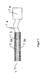
- FIGS. 1 to 3 Particular exemplary embodiments of inventive sensors and devices are in the FIGS. 1 to 3 shown.
- Reference numeral 1 denotes a sensor for selectively detecting liquids in energy storage devices, which is configured to selectively detect at least two of water, demineralized water, cooling medium and electrolyte.
- the sensor 1 further comprises two electrically conductive layers 2a, 2b between which a receiving layer 3 is arranged in the form of a dielectric.
- the electrically conductive layers 2 a, 2 b are connected via cables 4 to a signal evaluation unit 5.
- the electrically conductive layers 2a, 2b are arranged parallel to one another.
- the recording layer 3 in the form of the dielectric is electrically non-conductive and porous.
- a capacitance of the capacitor formed of the electrically conductive layers 2a, 2b and the recording layer 3 changes.
- the change in capacitance is dependent on the type of liquid or its dielectric constant.
- horizontal arrangement of the sensor 1 and the capacitor is not limiting, that is, the sensor 1 can also be arranged horizontally, or in any position.
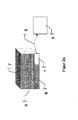
- FIG. 2 shows devices for storing energy with a sensor 1.
- a housing 7 of a battery 6 is shown in a perspective view.
- a sensor 1 is arranged horizontally and connected to a signal evaluation unit 5 by means of wireless means 9.
- FIG. 2b is contrary to the FIG. 2a the sensor 1 is not arranged in the housing 7 of the battery 6, but outside of the housing 7.
- the sensor 1 is connected via a line 10 to the housing 7, so that a liquid then be conducted by means of the connection 10 to the sensor for their selective detection can.
- This can be done gravitationally by the Sensor 1 is disposed below the housing 7, so that the liquid flows by gravity to the sensor 1, or in an active manner, for example by means of a pump which conveys the liquid to be detected to the sensor 1.
- FIG. 3a shows a sensor 1, which is arranged in a housing 7 of a battery 6.
- the sensor 1 comprises two electrically conductive layers 2a, 2b, between which a receiving layer 3 is arranged.
- the sensor 1 or the housing 7 are formed so that the lower conductive layer 2b of the sensor 1 is formed by the housing 7, that is, the lower conductive layer 2b of the sensor 1 forms a bottom B of the housing 7.
- the upper conductive Layer 2a is arranged separately from the housing 7.
- FIG. 3b Another possible embodiment of a device for storing energy in the form of a battery 6 with a sensor 1 is shown.
- a recess 8 is arranged in the lower region, that is in the region of the bottom B of the housing 7.
- the recess 8 serves both for the arrangement of the sensor 1 in the recess 8 and as a trough for collecting the liquids occurring in the housing 7.
- Figure 3c shows, in essence, a combination of embodiments of the devices according to the FIGS. 3a and 3b , A bottom B of the recess 8 is according to FIG. 3a formed, that is, the lower conductive layer 2b of the sensor 1 is formed by the bottom B of the recess or of the housing 7.
- the upper conductive layer 2a is arranged separately from the recess 8 or the housing 7.
- the invention has the advantage that in a simple and reliable way liquids in devices for storing energy can be detected and distinguished and thus damage to the energy storage can be avoided by liquids.
- an additional electrically insulating layer is applied.
- This is ideally firmly connected to the electrically conductive layers (leakage fluid can not pass through adhesion between the electrically conductive layer and the electrically insulating layer) and may be formed by insulating varnish, cover film (PA, Pl, PEN) or other thin-layer insulating materials.
- An electrically insulating lacquer can be sprayed on, painted on, or the like. and cover sheet are applied by lamination.
- Nonwovens showed a slightly worse signal resolution. This can be explained by the inhomogeneous overall layer thickness and the relatively low layer thicknesses of metal around the fibers. Nevertheless, even in these experiments, a fundamental suitability.
- FIGS. 4 and 5 show the selectivity with regard to the expected leakage media over time.
- the capacitance value shown here on the y-axis is proportional to the measuring capacity of the sensor. While the basic capacity of the sensor element in the unwetted case is at a low level (about 80 relative units), an aqueous solution, namely tap water, demineralized water or a water-glycol mixture (BASF GL48) leads to a sudden increase in the capacity Factor 40 to about 3250 relative units.
- aqueous solution namely tap water, demineralized water or a water-glycol mixture (BASF GL48
- Electrolytic solutions in turn have an even higher dielectric constant and lead to an approximately 1000 times higher relative capacity compared to the baseline and a 20-fold higher relative capacity compared to aqueous solutions.
- the presence of electrolytes can be detected even if the porous receiving layer was already completely soaked with water before contact with the electrolyte (see FIG. 5 ). Even small amounts ( ⁇ 1% by volume) of electrolyte then lead to a considerable increase in capacity.
- the sensor system is able to sensitively and selectively distinguish the occurring leakage media from each other.
- the sensitivity is especially high in the detection of electrolyte, which is practically particularly critical, and its distinction from the other media.
- Fig. 5 it is off Fig. 5 recognizable that a sensor already loaded with water, the recording layer is already fully occupied with water, with the addition of small amounts of electrolyte can detect this quickly and clearly.
- FIG. 4 It can be seen that the different aqueous media have a different capacity and thus are basically distinguishable.
Landscapes
- Engineering & Computer Science (AREA)
- Physics & Mathematics (AREA)
- Power Engineering (AREA)
- Chemical Kinetics & Catalysis (AREA)
- Electrochemistry (AREA)
- General Chemical & Material Sciences (AREA)
- Chemical & Material Sciences (AREA)
- Manufacturing & Machinery (AREA)
- Electromagnetism (AREA)
- Thermal Sciences (AREA)
- Fluid Mechanics (AREA)
- General Physics & Mathematics (AREA)
- Secondary Cells (AREA)
- Examining Or Testing Airtightness (AREA)
Priority Applications (1)
| Application Number | Priority Date | Filing Date | Title |
|---|---|---|---|
| EP10015556A EP2365575A1 (fr) | 2010-03-02 | 2010-12-13 | Capteur de liquide sélectif pour dispositifs destinés à stocker et à produire de l'énergie |
Applications Claiming Priority (2)
| Application Number | Priority Date | Filing Date | Title |
|---|---|---|---|
| EP10002114 | 2010-03-02 | ||
| EP10015556A EP2365575A1 (fr) | 2010-03-02 | 2010-12-13 | Capteur de liquide sélectif pour dispositifs destinés à stocker et à produire de l'énergie |
Publications (1)
| Publication Number | Publication Date |
|---|---|
| EP2365575A1 true EP2365575A1 (fr) | 2011-09-14 |
Family
ID=42830359
Family Applications (1)
| Application Number | Title | Priority Date | Filing Date |
|---|---|---|---|
| EP10015556A Withdrawn EP2365575A1 (fr) | 2010-03-02 | 2010-12-13 | Capteur de liquide sélectif pour dispositifs destinés à stocker et à produire de l'énergie |
Country Status (3)
| Country | Link |
|---|---|
| US (1) | US20110217573A1 (fr) |
| EP (1) | EP2365575A1 (fr) |
| BR (1) | BRPI1004719A2 (fr) |
Cited By (14)
| Publication number | Priority date | Publication date | Assignee | Title |
|---|---|---|---|---|
| WO2013037790A1 (fr) * | 2011-09-15 | 2013-03-21 | Avl List Gmbh | Accumulateur d'énergie électrique |
| DE102011089977A1 (de) * | 2011-12-27 | 2013-06-27 | Bayerische Motoren Werke Aktiengesellschaft | Fahrzeug mit Hochvoltspeicher |
| WO2013164149A1 (fr) * | 2012-05-02 | 2013-11-07 | Robert Bosch Gmbh | Procédé et dispositif pour juger de l'état d'un accumulateur électrochimique et système d'accumulation électrochimique |
| DE102013206922A1 (de) * | 2013-04-17 | 2014-05-08 | Continental Automotive Gmbh | Batteriesystem und Messsonde zur Detektion von Flusssäure |
| DE102013212593A1 (de) * | 2013-06-28 | 2014-12-31 | Robert Bosch Gmbh | Vorrichtung und Verfahren zur Überwachung von Feuchte in einem elektrischen System, Batteriegehäuse und Batteriesystem |
| DE102014203919A1 (de) * | 2014-03-04 | 2015-09-10 | Robert Bosch Gmbh | Vorrichtung und Verfahren zur Überwachung eines Batteriesystems sowie Batterie, Batteriesystem und Fahrzeug |
| WO2017005333A1 (fr) * | 2015-07-06 | 2017-01-12 | Sartorius Stedim Biotech Gmbh | Procédé pour mesurer une pluralité de paramètres d'état d'un fluide contenu dans un récipient |
| DE102013001311B4 (de) | 2013-01-26 | 2019-10-10 | Audi Ag | Kraftfahrzeug |
| WO2021160515A1 (fr) * | 2020-02-13 | 2021-08-19 | Daimler Ag | Détection d'une fuite dans un circuit refroidissement |
| DE102019214104B4 (de) | 2019-09-17 | 2021-11-11 | Vitesco Technologies GmbH | Verfahren zum Erkennen eines thermischen Durchgehens einer Batteriezelle eines Batteriemoduls für ein Fahrzeug und Batteriemodul |
| US11370478B2 (en) | 2017-08-23 | 2022-06-28 | Volkswagen Aktiengesellschaft | Steering system for a transportation vehicle |
| WO2023104503A1 (fr) * | 2021-12-09 | 2023-06-15 | Bayerische Motoren Werke Aktiengesellschaft | Batterie haute tension pour véhicule et véhicule |
| DE102022113202A1 (de) | 2022-05-25 | 2023-11-30 | Eberspächer Catem Gmbh & Co. Kg | Brennstoffzellen-Abgasanlage und Verfahren zum Betreiben einer Brennstoffzellen-Abgasanlage |
| DE102023002541B4 (de) | 2023-06-23 | 2025-02-27 | Mercedes-Benz Group AG | Vorrichtung zur Überwachung eines Elektrogehäuses, insbesondere eines Batteriegehäuses |
Families Citing this family (15)
| Publication number | Priority date | Publication date | Assignee | Title |
|---|---|---|---|---|
| KR20120059105A (ko) * | 2010-11-30 | 2012-06-08 | 현대자동차주식회사 | 고전압 배터리팩의 수분 배출장치 |
| US20120251859A1 (en) * | 2011-03-31 | 2012-10-04 | Lg Chem, Ltd. | Battery pack having liquid leak detection system |
| WO2013063445A2 (fr) * | 2011-10-28 | 2013-05-02 | President And Fellows Of Harvard College | Accéléromètres et capteurs tactiles basé sur de papier, capacitifs |
| US8865333B2 (en) * | 2012-07-17 | 2014-10-21 | GM Global Technology Operations LLC | Systems and methods for mitigating battery damage caused by coolant leaks |
| DE102013210378B4 (de) | 2013-06-05 | 2022-08-25 | Robert Bosch Gmbh | Lithium-Ionen-Batteriezelle mit einem kapazitiven Sensor, Verfahren zum Überwachen des Zustandes einer solchen Lithium-Ionen-Batteriezelle, Batteriesystem und Fahrzeug |
| US10161895B2 (en) * | 2014-12-23 | 2018-12-25 | 3M Innovative Properties Company | Electronic moisture sensor |
| EP3078964B1 (fr) * | 2015-04-09 | 2017-05-24 | Honeywell International Inc. | Capteur d'humidité relative et procédé |
| FR3051906B1 (fr) * | 2016-05-24 | 2022-12-16 | Coutier Moulage Gen Ind | Dispositif de securite pour carte electronique capable d’identifier une fuite de solution aqueuse d’uree |
| CN109932403A (zh) * | 2017-12-19 | 2019-06-25 | 天津工业大学 | 一种用于宽幅被测物的电容传感器检测装置 |
| DE102018209082A1 (de) * | 2018-06-07 | 2019-12-12 | Axagarius Gmbh & Co. Kg | Test zur Bestimmung der Phosphat-Konzentration |
| DE102018213911A1 (de) * | 2018-08-17 | 2020-02-20 | Robert Bosch Gmbh | Zellkontaktierungssystem für eine modular aufgebaute Batterie |
| DE102021204012A1 (de) | 2021-04-22 | 2022-10-27 | Volkswagen Aktiengesellschaft | Batterie mit einem in einem Batteriegehäuse angeordneten Flüssigkeitssensor sowie Fahrzeug mit einer solchen Batterie |
| US20250003915A1 (en) * | 2021-11-12 | 2025-01-02 | Sensative Ab | Capacitive oil sensor assembly |
| CN218472170U (zh) * | 2022-09-30 | 2023-02-10 | 比亚迪股份有限公司 | 电池托盘组件、电池包、车辆 |
| DE102023204138A1 (de) | 2023-05-04 | 2024-11-07 | Mahle International Gmbh | Batteriesystem, insbesondere zum Antreiben eines Fahrzeuges |
Citations (8)
| Publication number | Priority date | Publication date | Assignee | Title |
|---|---|---|---|---|
| US4045721A (en) * | 1974-12-30 | 1977-08-30 | Swain William H | Electro-chemical concentration transducer and its use to measure and control acid strength and storage battery charge |
| US5269175A (en) * | 1984-04-06 | 1993-12-14 | Fraunhofer-Gesellschaft Zur Forderung Der Angewandten Forschung E.V. | Sensor for investigating liquids |
| JPH11191403A (ja) * | 1997-12-26 | 1999-07-13 | Sanyo Electric Co Ltd | パック電池 |
| WO2002037098A1 (fr) * | 2000-11-02 | 2002-05-10 | Quallion Llc | Procede permettant de determiner s'il y a des fuites dans un contenant |
| EP1841002A1 (fr) * | 2006-03-31 | 2007-10-03 | Sony Deutschland Gmbh | Systeme de detection de fuite dans une batterie |
| JP2008060000A (ja) * | 2006-09-01 | 2008-03-13 | Sony Corp | 電池パックおよび電子機器 |
| DE102007063280A1 (de) | 2007-12-27 | 2009-07-02 | Robert Bosch Gmbh | Batteriesensor mit drahtloser Datenübertragung |
| DE102008013407A1 (de) | 2008-03-10 | 2009-09-17 | Robert Bosch Gmbh | Sensoranordnung für die Zustandserkennung einer Batterie |
Family Cites Families (1)
| Publication number | Priority date | Publication date | Assignee | Title |
|---|---|---|---|---|
| JPS6221033A (ja) * | 1985-07-19 | 1987-01-29 | Fuji Electric Co Ltd | 漏水検知センサ |
-
2010
- 2010-11-09 US US12/942,760 patent/US20110217573A1/en not_active Abandoned
- 2010-11-12 BR BRPI1004719-0A patent/BRPI1004719A2/pt not_active IP Right Cessation
- 2010-12-13 EP EP10015556A patent/EP2365575A1/fr not_active Withdrawn
Patent Citations (8)
| Publication number | Priority date | Publication date | Assignee | Title |
|---|---|---|---|---|
| US4045721A (en) * | 1974-12-30 | 1977-08-30 | Swain William H | Electro-chemical concentration transducer and its use to measure and control acid strength and storage battery charge |
| US5269175A (en) * | 1984-04-06 | 1993-12-14 | Fraunhofer-Gesellschaft Zur Forderung Der Angewandten Forschung E.V. | Sensor for investigating liquids |
| JPH11191403A (ja) * | 1997-12-26 | 1999-07-13 | Sanyo Electric Co Ltd | パック電池 |
| WO2002037098A1 (fr) * | 2000-11-02 | 2002-05-10 | Quallion Llc | Procede permettant de determiner s'il y a des fuites dans un contenant |
| EP1841002A1 (fr) * | 2006-03-31 | 2007-10-03 | Sony Deutschland Gmbh | Systeme de detection de fuite dans une batterie |
| JP2008060000A (ja) * | 2006-09-01 | 2008-03-13 | Sony Corp | 電池パックおよび電子機器 |
| DE102007063280A1 (de) | 2007-12-27 | 2009-07-02 | Robert Bosch Gmbh | Batteriesensor mit drahtloser Datenübertragung |
| DE102008013407A1 (de) | 2008-03-10 | 2009-09-17 | Robert Bosch Gmbh | Sensoranordnung für die Zustandserkennung einer Batterie |
Non-Patent Citations (1)
| Title |
|---|
| LAMM ET AL.: "Lithium-Ionen-Batterie. Erster Serieneinsatz im S400 Hybrid", ATZ, vol. 111, 2009, pages 490F |
Cited By (17)
| Publication number | Priority date | Publication date | Assignee | Title |
|---|---|---|---|---|
| WO2013037790A1 (fr) * | 2011-09-15 | 2013-03-21 | Avl List Gmbh | Accumulateur d'énergie électrique |
| DE102011089977A1 (de) * | 2011-12-27 | 2013-06-27 | Bayerische Motoren Werke Aktiengesellschaft | Fahrzeug mit Hochvoltspeicher |
| DE102011089977B4 (de) | 2011-12-27 | 2022-12-29 | Bayerische Motoren Werke Aktiengesellschaft | Fahrzeug mit Hochvoltspeicher |
| WO2013164149A1 (fr) * | 2012-05-02 | 2013-11-07 | Robert Bosch Gmbh | Procédé et dispositif pour juger de l'état d'un accumulateur électrochimique et système d'accumulation électrochimique |
| DE102013001311B4 (de) | 2013-01-26 | 2019-10-10 | Audi Ag | Kraftfahrzeug |
| DE102013206922A1 (de) * | 2013-04-17 | 2014-05-08 | Continental Automotive Gmbh | Batteriesystem und Messsonde zur Detektion von Flusssäure |
| DE102013212593A1 (de) * | 2013-06-28 | 2014-12-31 | Robert Bosch Gmbh | Vorrichtung und Verfahren zur Überwachung von Feuchte in einem elektrischen System, Batteriegehäuse und Batteriesystem |
| DE102014203919A1 (de) * | 2014-03-04 | 2015-09-10 | Robert Bosch Gmbh | Vorrichtung und Verfahren zur Überwachung eines Batteriesystems sowie Batterie, Batteriesystem und Fahrzeug |
| WO2017005333A1 (fr) * | 2015-07-06 | 2017-01-12 | Sartorius Stedim Biotech Gmbh | Procédé pour mesurer une pluralité de paramètres d'état d'un fluide contenu dans un récipient |
| US10802033B2 (en) | 2015-07-06 | 2020-10-13 | Sartorius Stedim Biotech Gmbh | Method for measuring a plurality of status parameters of a fluid contained in a container |
| US11370478B2 (en) | 2017-08-23 | 2022-06-28 | Volkswagen Aktiengesellschaft | Steering system for a transportation vehicle |
| DE102019214104B4 (de) | 2019-09-17 | 2021-11-11 | Vitesco Technologies GmbH | Verfahren zum Erkennen eines thermischen Durchgehens einer Batteriezelle eines Batteriemoduls für ein Fahrzeug und Batteriemodul |
| WO2021160515A1 (fr) * | 2020-02-13 | 2021-08-19 | Daimler Ag | Détection d'une fuite dans un circuit refroidissement |
| WO2023104503A1 (fr) * | 2021-12-09 | 2023-06-15 | Bayerische Motoren Werke Aktiengesellschaft | Batterie haute tension pour véhicule et véhicule |
| DE102021132430A1 (de) | 2021-12-09 | 2023-06-15 | Bayerische Motoren Werke Aktiengesellschaft | Hochvoltspeicher für ein Fahrzeug und Fahrzeug |
| DE102022113202A1 (de) | 2022-05-25 | 2023-11-30 | Eberspächer Catem Gmbh & Co. Kg | Brennstoffzellen-Abgasanlage und Verfahren zum Betreiben einer Brennstoffzellen-Abgasanlage |
| DE102023002541B4 (de) | 2023-06-23 | 2025-02-27 | Mercedes-Benz Group AG | Vorrichtung zur Überwachung eines Elektrogehäuses, insbesondere eines Batteriegehäuses |
Also Published As
| Publication number | Publication date |
|---|---|
| US20110217573A1 (en) | 2011-09-08 |
| BRPI1004719A2 (pt) | 2012-06-26 |
Similar Documents
| Publication | Publication Date | Title |
|---|---|---|
| EP2365575A1 (fr) | Capteur de liquide sélectif pour dispositifs destinés à stocker et à produire de l'énergie | |
| EP2550702B1 (fr) | Système de surveillance pour un accumulateur d'énergie | |
| DE102016212986B4 (de) | Flüssigkeitsmessvorrichtung und Messkopfvorrichtung zur Feuchtigkeitsdetektion, insbesondere in Behältnissen für flüssigkeitssensitive Elektrik- und/oder Elektronikkomponenten in Straßenfahrzeugen | |
| DE102011016527A1 (de) | Vorrichtung und Verfahren zur Dichtheitsüberprüfung eines elektrochemischen Energiespeichers | |
| EP2452392B1 (fr) | Dispositif servant au test sécurisé de batteries | |
| EP3560011B1 (fr) | Cellule électrochimique rechargeable avec une couche de séparateur en céramique et une électrode indicatrice | |
| EP2646785B1 (fr) | Dispositif permettant de détecter la température d'un accumulateur d'énergie | |
| DE102017119818B4 (de) | Batteriezellensystem und batteriezellenüberwachungssystem | |
| WO2019141698A1 (fr) | Dispositif de détection pour détecter une déformation d'un boîtier d'un accumulateur haute tension d'un véhicule automobile | |
| DE112009000073T5 (de) | Batterie und Batteriesystem | |
| DE102010012927A1 (de) | Vorrichtung zur Detektion von Undichtheiten | |
| WO2012095292A2 (fr) | Batterie avec dispositif de commande et procédé de fonctionnement de cette batterie | |
| DE102014006807A1 (de) | Batteriesystem mit Sensorvorrichtung | |
| DE102010020911A1 (de) | Anordnung und Verfahren zum sicheren Entladen eines Energiespeichers | |
| DE102012223708A1 (de) | Batteriezelle mit Drucksensor | |
| KR20100047331A (ko) | 미세 섬유 스페이서를 사용하는 개선된 알루미늄 전해 커패시터 | |
| DE102019125236A1 (de) | Batteriezelle mit einer Diagnoseeinheit, Verfahren zur Zustandsdiagnose einer Batteriezelle, Batterie sowie Kraftfahrzeug mit einer Batterie | |
| DE102012205929A1 (de) | Sicherheitssensorsystem für ein elektrochemisches Speichersystem | |
| DE102022002966A1 (de) | Vorrichtung zur Detektion von Wasser in einem Gehäuse eines elektrischen Energiespeichers | |
| DE102020213990A1 (de) | Elektrischer Energiespeicher, Vorrichtung und Verfahren zum Betreiben eines elektrischen Energiespeichers | |
| US20090122466A1 (en) | Electrochemical capacitors | |
| WO2016091567A1 (fr) | Élément lithium-ions | |
| DE102020105440A1 (de) | Verfahren zum Überwachen einer Batterie mittels einer Sensorvorrichtung, Batterie mit einer Sensorvorrichtung sowie Kraftfahrzeug mit einer Batterie | |
| DE102011120879A1 (de) | Batterie | |
| WO2014095145A1 (fr) | Élément de batterie comportant un capteur d'accélération |
Legal Events
| Date | Code | Title | Description |
|---|---|---|---|
| PUAI | Public reference made under article 153(3) epc to a published international application that has entered the european phase |
Free format text: ORIGINAL CODE: 0009012 |
|
| AK | Designated contracting states |
Kind code of ref document: A1 Designated state(s): AL AT BE BG CH CY CZ DE DK EE ES FI FR GB GR HR HU IE IS IT LI LT LU LV MC MK MT NL NO PL PT RO RS SE SI SK SM TR |
|
| AX | Request for extension of the european patent |
Extension state: BA ME |
|
| 17P | Request for examination filed |
Effective date: 20110829 |
|
| 17Q | First examination report despatched |
Effective date: 20121127 |
|
| STAA | Information on the status of an ep patent application or granted ep patent |
Free format text: STATUS: THE APPLICATION IS DEEMED TO BE WITHDRAWN |
|
| 18D | Application deemed to be withdrawn |
Effective date: 20130409 |