EP2365599B1 - Dispositif de conversion d'énergie électrique et procédé de fonctionnement d'un tel dispositif - Google Patents
Dispositif de conversion d'énergie électrique et procédé de fonctionnement d'un tel dispositif Download PDFInfo
- Publication number
- EP2365599B1 EP2365599B1 EP10155828.6A EP10155828A EP2365599B1 EP 2365599 B1 EP2365599 B1 EP 2365599B1 EP 10155828 A EP10155828 A EP 10155828A EP 2365599 B1 EP2365599 B1 EP 2365599B1
- Authority
- EP
- European Patent Office
- Prior art keywords
- converter
- voltage
- clock frequency
- input voltage
- stage
- Prior art date
- Legal status (The legal status is an assumption and is not a legal conclusion. Google has not performed a legal analysis and makes no representation as to the accuracy of the status listed.)
- Not-in-force
Links
Images



Classifications
-
- H—ELECTRICITY
- H02—GENERATION; CONVERSION OR DISTRIBUTION OF ELECTRIC POWER
- H02J—ELECTRIC POWER NETWORKS; CIRCUIT ARRANGEMENTS OR SYSTEMS FOR SUPPLYING OR DISTRIBUTING ELECTRIC POWER; SYSTEMS FOR STORING ELECTRIC ENERGY
- H02J3/00—Circuit arrangements for AC mains or AC distribution networks
- H02J3/36—Arrangements for transfer of electric power between AC networks via high-voltage DC [HVDC] links; Arrangements for transfer of electric power between generators and networks via HVDC links
-
- H—ELECTRICITY
- H02—GENERATION; CONVERSION OR DISTRIBUTION OF ELECTRIC POWER
- H02J—ELECTRIC POWER NETWORKS; CIRCUIT ARRANGEMENTS OR SYSTEMS FOR SUPPLYING OR DISTRIBUTING ELECTRIC POWER; SYSTEMS FOR STORING ELECTRIC ENERGY
- H02J1/00—Circuit arrangements for DC mains or DC distribution networks
- H02J1/10—Parallel operation of DC sources
- H02J1/102—Parallel operation of DC sources being switching converters
-
- H—ELECTRICITY
- H02—GENERATION; CONVERSION OR DISTRIBUTION OF ELECTRIC POWER
- H02J—ELECTRIC POWER NETWORKS; CIRCUIT ARRANGEMENTS OR SYSTEMS FOR SUPPLYING OR DISTRIBUTING ELECTRIC POWER; SYSTEMS FOR STORING ELECTRIC ENERGY
- H02J1/00—Circuit arrangements for DC mains or DC distribution networks
- H02J1/10—Parallel operation of DC sources
-
- H—ELECTRICITY
- H02—GENERATION; CONVERSION OR DISTRIBUTION OF ELECTRIC POWER
- H02J—ELECTRIC POWER NETWORKS; CIRCUIT ARRANGEMENTS OR SYSTEMS FOR SUPPLYING OR DISTRIBUTING ELECTRIC POWER; SYSTEMS FOR STORING ELECTRIC ENERGY
- H02J3/00—Circuit arrangements for AC mains or AC distribution networks
- H02J3/38—Arrangements for feeding a single network from two or more generators or sources in parallel; Arrangements for feeding already energised networks from additional generators or sources in parallel
- H02J3/381—Dispersed generators
-
- H—ELECTRICITY
- H02—GENERATION; CONVERSION OR DISTRIBUTION OF ELECTRIC POWER
- H02J—ELECTRIC POWER NETWORKS; CIRCUIT ARRANGEMENTS OR SYSTEMS FOR SUPPLYING OR DISTRIBUTING ELECTRIC POWER; SYSTEMS FOR STORING ELECTRIC ENERGY
- H02J3/00—Circuit arrangements for AC mains or AC distribution networks
- H02J3/38—Arrangements for feeding a single network from two or more generators or sources in parallel; Arrangements for feeding already energised networks from additional generators or sources in parallel
- H02J3/46—Controlling the sharing of generated power between the generators, sources or networks
-
- H—ELECTRICITY
- H02—GENERATION; CONVERSION OR DISTRIBUTION OF ELECTRIC POWER
- H02M—APPARATUS FOR CONVERSION BETWEEN AC AND AC, BETWEEN AC AND DC, OR BETWEEN DC AND DC, AND FOR USE WITH MAINS OR SIMILAR POWER SUPPLY SYSTEMS; CONVERSION OF DC OR AC INPUT POWER INTO SURGE OUTPUT POWER; CONTROL OR REGULATION THEREOF
- H02M3/00—Conversion of DC power input into DC power output
- H02M3/02—Conversion of DC power input into DC power output without intermediate conversion into AC
- H02M3/04—Conversion of DC power input into DC power output without intermediate conversion into AC by static converters
- H02M3/10—Conversion of DC power input into DC power output without intermediate conversion into AC by static converters using discharge tubes with control electrode or semiconductor devices with control electrode
- H02M3/145—Conversion of DC power input into DC power output without intermediate conversion into AC by static converters using discharge tubes with control electrode or semiconductor devices with control electrode using devices of a triode or transistor type requiring continuous application of a control signal
- H02M3/155—Conversion of DC power input into DC power output without intermediate conversion into AC by static converters using discharge tubes with control electrode or semiconductor devices with control electrode using devices of a triode or transistor type requiring continuous application of a control signal using semiconductor devices only
-
- H—ELECTRICITY
- H02—GENERATION; CONVERSION OR DISTRIBUTION OF ELECTRIC POWER
- H02M—APPARATUS FOR CONVERSION BETWEEN AC AND AC, BETWEEN AC AND DC, OR BETWEEN DC AND DC, AND FOR USE WITH MAINS OR SIMILAR POWER SUPPLY SYSTEMS; CONVERSION OF DC OR AC INPUT POWER INTO SURGE OUTPUT POWER; CONTROL OR REGULATION THEREOF
- H02M7/00—Conversion of AC power input into DC power output; Conversion of DC power input into AC power output
- H02M7/42—Conversion of DC power input into AC power output without possibility of reversal
- H02M7/44—Conversion of DC power input into AC power output without possibility of reversal by static converters
- H02M7/48—Conversion of DC power input into AC power output without possibility of reversal by static converters using discharge tubes with control electrode or semiconductor devices with control electrode
-
- H—ELECTRICITY
- H02—GENERATION; CONVERSION OR DISTRIBUTION OF ELECTRIC POWER
- H02M—APPARATUS FOR CONVERSION BETWEEN AC AND AC, BETWEEN AC AND DC, OR BETWEEN DC AND DC, AND FOR USE WITH MAINS OR SIMILAR POWER SUPPLY SYSTEMS; CONVERSION OF DC OR AC INPUT POWER INTO SURGE OUTPUT POWER; CONTROL OR REGULATION THEREOF
- H02M7/00—Conversion of AC power input into DC power output; Conversion of DC power input into AC power output
- H02M7/42—Conversion of DC power input into AC power output without possibility of reversal
- H02M7/44—Conversion of DC power input into AC power output without possibility of reversal by static converters
- H02M7/48—Conversion of DC power input into AC power output without possibility of reversal by static converters using discharge tubes with control electrode or semiconductor devices with control electrode
- H02M7/4807—Conversion of DC power input into AC power output without possibility of reversal by static converters using discharge tubes with control electrode or semiconductor devices with control electrode having a high frequency intermediate AC stage
-
- H—ELECTRICITY
- H02—GENERATION; CONVERSION OR DISTRIBUTION OF ELECTRIC POWER
- H02J—ELECTRIC POWER NETWORKS; CIRCUIT ARRANGEMENTS OR SYSTEMS FOR SUPPLYING OR DISTRIBUTING ELECTRIC POWER; SYSTEMS FOR STORING ELECTRIC ENERGY
- H02J2101/00—Supply or distribution of decentralised, dispersed or local electric power generation
- H02J2101/20—Dispersed power generation using renewable energy sources
- H02J2101/30—Fuel cells
Definitions
- the invention relates to a device according to the preamble of claim 1. It is used for the conversion of electrical energy stored in an electrochemical storage (for example in a rechargeable battery) and is removed from this or is taken from a fuel cell or supplied to it. Furthermore, the invention relates to a method for operating such devices.
- Such inverters must be designed for operation in a wide input voltage range, especially in an input voltage range of 1: 2 to 1: 3, since the DC voltage generated by, for example, a fuel cell can vary considerably, for example between 25 V and 72 V. It is also for example, in fuel cells possibly also necessary to provide them with energy, for example, to start the operation of the fuel cell, for which a DC voltage of eg 24 V is to be supplied.
- a device with a single DC / DC converter stage for generating a DC link voltage from an input voltage which is designed and controllable such that it converts DC voltage directly to an intermediate circuit voltage, with which a single DC / AC converter stage for generating the AC voltage is operable, wherein the DC / DC converter stage comprises two or more DC / DC converter devices connected in parallel, which are galvanically separated and each having a transformer, a control device which comprises the two or more DC / DC converter means connected in parallel with control parameters, and the DC / AC converter stage for generating the AC voltage from the DC link voltage known.
- the invention reduces the effort required for the conversion of energy at a wide input voltage range of, for example, 1: 2 to 1: 3, wherein the device should be performed simultaneously galvanic separating.
- the invention achieves this goal by the device according to claim 1 and the method according to claim 8.
- the variants of the control method according to the invention make it possible for the inverter to generate alternating voltage from the input voltage to reduce a two-stage structure, in particular with a single DC / DC converter stage and the actual DC / AC converter stage.
- the DC / DC converter stage consists of two or more parallel-connected DC / DC converter devices whose inputs and outputs are conductively connected to each other. Nevertheless, by suitable individual activation of the power semiconductors of the two or more parallel-connected DC / DC converter devices from a wide input voltage range of for example 25 V to 72 V, a mains voltage of, for example, more than 100 V, in particular 230 V can be generated. It is preferable in terms of optimum efficiency, to regulate the DC link voltage to the actual mains peak voltage.
- the two or more DC / DC converter devices connected in parallel may be all or partly dimensioned identically as well as differently and be controlled both equally and differently in both cases.
- a different control of the same designed converter means is provided, which, for example, is useful to turn off one of the converter while the other is running. This "switching off” is preferably done in that the switches or valves of the converter are no longer controlled, so all are open.
- the invention advantageously achieves that the number of DC / DC converter stages of a device connected in series according to the prior art is preferably reduced to a single one, which subsequently leads to a reduction of the hardware expenditure, e.g. to control the individual DC / DC converter stages and thus leads to cheaper production costs. Furthermore, an increase in the efficiency of the device in question is made possible by the invention.
- this further DC / DC converter stage is used to generate a DC voltage to supply the fuel cell, so for example to generate a DC voltage of 24 V.
- This is the actual DC / AC converter stage designed for bidirectional operation and it may be, for.
- the DC link voltage is advantageously generated by converting the DC voltage generated by the fuel cell.
- Fig. 1a shows a first embodiment of a device 1 according to the invention with an electrochemical energy generator which generates electrical energy by conversion from another form of energy, or electrochemical storage 2 (for example a rechargeable battery or a fuel cell), a DC / DC converter stage 3 and a DC / AC converter stage 4.
- electrochemical energy generator which generates electrical energy by conversion from another form of energy, or electrochemical storage 2 (for example a rechargeable battery or a fuel cell), a DC / DC converter stage 3 and a DC / AC converter stage 4.
- the output terminals of the power generator or memory 2 are connected via electrical lines 5 and 6 to the terminals of the battery side of the preferably bidirectionally operable DC / DC converter stage 3. Between the lines 5 and 6, the output voltage of the power generator or memory 2 is applied. This is designated by a voltage arrow 7.
- the DC bus terminals of the DC / DC converter stage 3 are connected via electrical lines 8 and 9 to the terminals of the DC side of the preferably bidirectionally operable DC / AC converter stage 4.
- the area between the DC / DC converter stage 3 and the DC / AC converter stage 4 is also referred to as a DC link, accordingly the voltage symbolized by the voltage arrow 10 is also referred to as a DC link voltage.
- the terminals of the AC side of the DC / AC converter stage 4 are connected via electrical lines 11 and 12 to an electrical network 13 (for example, a 230V, 50 Hz power supply network), accordingly is between the lines 11 and 12 a symbolized by the voltage arrow 14 Mains voltage on.
- an electrical network 13 for example, a 230V, 50 Hz power supply network
- the preferred - but not mandatory - bidirectional operation of the DC / DC converter stage 3 and the DC / AC converter stage 4 is represented by the directional arrows 15 and 16.
- the battery voltage 7 is converted to the intermediate circuit voltage level 10 by means of the DC / DC converter stage 3. Subsequently, the intermediate circuit voltage 10 is converted by the DC / AC converter stage 4 to the mains voltage level 14 and fed into the network 13.
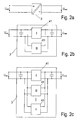
- the DC / DC converter stage 3 has a plurality of parallel-connected DC / DC converter devices.
- DC / DC converter stage 3 can therefore as in Fig. 2b represented two, or as in Fig. 2c shown, n DC / DC converter devices include.
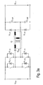
- FIG. 3a An exemplary circuit of a DC / DC converter device in unidirectional design is shown in FIG Fig. 3a and an exemplary circuit of a bidirectional DC / DC converter device is shown in FIG Fig. 3b shown. Further shows Fig. 3c an exemplary electronic circuit of a parallel connection of two DC / DC converter devices.
- the in the Fig. 3a and 3b 3c and 3c are merely examples of DC / DC converter devices which may be used in the present invention.
- the components of the exemplary circuits are therefore not provided with reference numerals for reasons of clarity, but merely provided with the generally known designations for a respective component (V for valve or power semiconductor, C for capacitor, Ü for transformer, etc.).
- the DC / DC converter devices are galvanically isolating and accordingly have a high-frequency transformer and are in both a hard-switching and in a resonant switching mode, in particular "Zero Current Switching" (ZCS) and “Zero Voltage Switching" (US Pat. ZVS) as well as variants of these operating modes, operable.
- ZCS Zero Current Switching
- US Pat. ZVS Zero Voltage Switching
- the DC / DC converter stage 3 may include a plurality (two or more) DC / DC converter means 41 which do not differ in a number of characteristics characterizing a DC / DC converter means, in other words, the DC / DC converter stage 3 may have a plurality DC / DC converter means 41 which are dimensioned similar or ausgestaltet.
- the DC / DC converter stage 3 may further comprise a plurality of DC / DC converter means 41 which differ in a number of characteristics characterizing a DC / DC converter means, in other words the DC / DC converter stage 3 may comprise a plurality of DC / DC converter means 41, which are dimensioned differently or configured.
- a DC / DC converter device is characterized for example by one or more of the following characteristic values: an input voltage range, an output voltage range, a rated power, a minimum or a maximum clock frequency and / or a minimum or maximum duty cycle.
- the DC / DC converter device can be operated in different modes.
- the operating mode of a DC / DC converter device can be defined by control parameters. These can be stored, for example, in a control device, not shown, wherein the control device controls the plurality of DC / DC converter devices corresponding to a number of control parameters.
- the control parameters relate to: a clock frequency and a duty cycle of the rectangular pulse trains for opening and closing the switches or valves of a DC / DC converter device. Furthermore, the control parameters are changed depending on an input voltage and / or an electrical power to be transmitted.
- a converter stage 3 may have two differently configured or dimensioned DC / DC converter devices 41.
- An exemplary control of two differently configured or dimensioned DC / DC converter devices of a converter stage 3 is in the Fig. 4a to 4d by way of example as a function of the input voltage U, one of the converter stage 3 is shown.
- FIGS. 4a to 4d clear that with increasing input voltage U a first, the first DC / DC converter is in operation WE1 ( Fig. 4d ).
- the clock frequency f of the first DC / DC converting means is a increases with the increasing input voltage U, here up to the point of maximum frequency f max ( Fig. 4a ). With further increases in input voltage U a first DC / DC converter means WE1 is then turned off ( Fig. 4d ) and the second DC / DC converter WE2 ( Fig. 4c ). With further increases in input voltage U a of the converter stage, the clock frequency f of the second DC / DC converting means is further - here up to the maximum operating frequency f max - increased ( Fig. 4a ). If the input voltage continues to increase, the clock frequency remains constant in the example shown ( Fig.
- the duty ratio g of the second DC / DC converting means is lowered with further increases in input voltage U a of 0.5 to the minimum duty ratio g min. Alternatively, it may u. U. also be useful to lower with decreasing modulation g and the clock frequency.
- the first DC / DC converter means covers in the illustrated example the lower portion of the input voltage U off while covering the upper portion of the input voltage U a a second DC / DC converter means.
- a converter stage 3 may have two identically configured or dimensioned DC / DC converter devices 41.
- An exemplary control of two identically designed or dimensioned DC / DC converter devices a converter stage 3 is in the Fig. 5a to 5d by way of example as a function of the input voltage U, one of the converter stage 3 is shown.
- a further device 20 has a power generator, for example a fuel cell 21, a DC / DC converter stage 22 (unidirectional, see arrow 22a) and a DC / AC converter stage 23 (bidirectional, see arrow 23a).
- the output terminals of the fuel cell 21 are connected via electrical lines 24 and 25 to the terminals of the fuel cell side of the DC / DC converter stage 22. Between the lines 24 and 25 is a symbolized by the voltage arrow 26 fuel cell voltage.
- the intermediate circuit terminals of the DC / DC converter stage 22 are connected via electrical lines 27 and 28 to the intermediate circuit terminals of the DC / AC converter stage 23. Between the lines 27 and 28 is an symbolized by the voltage arrow 29 DC link voltage. Via electrical lines 30 and 31 are the AC terminals of the DC / AC converter stage 23 are connected to a network 32 (for example a 230V, 50 Hz power supply network). Between the lines 30 and 31 is a symbolized by the voltage arrow 40 mains voltage.
- the device 20 has a system periphery (BoP) shown as block 33, which is required for operating the fuel cell and requires electrical energy.
- BoP system periphery
- the plant periphery 33 of the fuel cell 21 is connected to the output terminals of the DC / DC converter stage 36 (unidirectionally, see arrow 36a). Between the lines 34 and 35 is symbolized by the voltage arrow 37 supply voltage for the system periphery 33 at.
- the input terminals of the DC / DC converter stage 36 are connected to the intermediate circuit of the device 20 via electrical lines 38 and 39 according to a further development, but also independently considered variant.
- the tap of the voltage required for the supply of the system periphery is thus directly on the DC link and does not need to be adjusted as in the prior art initially via boost / buck converter.
- the converter stages 22 and 36 can be controlled and executed analogously to the converter stage 3 described in the first embodiment, in this way, also previously required boost converter / step-down converter are no longer required in the apparatus 20.
Landscapes
- Engineering & Computer Science (AREA)
- Power Engineering (AREA)
- Dc-Dc Converters (AREA)
- Fuel Cell (AREA)
Claims (11)
- Dispositif pour la conversion d'une tension continue en provenance d'un accumulateur électrochimique (2) ou en provenance d'une pile à combustible (21) en une tension alternative, en particulier pour l'alimentation dans un réseau d'approvisionnement (13, 32), présentant une structure biétagée comprenant :i. un seul étage de conversion CC/CC (3, 22) pour la production d'une tension de circuit intermédiaire à partir de la tension de sortie de l'accumulateur électrochimique (2) ou de la pile à combustible (21), ledit étage de conversion est configuré et est commandable de telle manière qu'il convertit, en particulier qu'il amplifie, la tension continue, dans une large plage de tension d'entrée, directement en la tension de circuit intermédiaire, avec laquelle un seul étage de conversion CC/CA (4, 23) est apte à fonctionner pour la production de la tension alternative, sachant que l'étage de conversion CC/CC (3, 22) présente un dispositif convertisseur CC/CC (41), qui est réalisé avec une séparation galvanique et qui présente un transformateur haute fréquence, et un dispositif de commande, le dispositif de commande le dispositif convertisseur CC/CC (41) à l'aide de paramètres de commande, etii. l'étage de conversion CC/CA (4, 23) pour la production de la tension alternative à partir de la tension de circuit intermédiaire, sachantiii. que l'étage de conversion CC/CC (3, 22) présente deux ou plus dispositifs convertisseurs CC/CC (41) branchés en parallèle, lesquels sont réalisés avec une séparation galvanique et présentent chacun un transformateur haute fréquence, etiv. que le dispositif de commande commande les deux ou plus dispositifs convertisseurs CC/CC (41) branchés en parallèle à l'aide de paramètres de commande variant en fonction d'une tension d'entrée Uentrée de l'étage de conversion et/ou d'une puissance électrique à transmettre, lesdits paramètres de commande concernant : une fréquence d'horloge et/ou un taux d'impulsions de séquences d'impulsions rectangulaires pour l'ouverture et la fermeture des commutateurs du dispositif convertisseur CC/CC, caractérisé en ce quev. le dispositif de commande, commande de manière différente et individuelle les deux ou plus dispositifs convertisseurs CC/CC branchés en parallèle.
- Dispositif selon la revendication 1, caractérisé en ce que les deux ou plus dispositifs convertisseurs CC/CC (41) branchés en parallèle présentent une même configuration concernant une ou plusieurs valeurs caractéristiques qui suivent : plage de tension d'entrée, plage de tension de sortie, puissance nominale, fréquence d'horloge maximale, fréquence d'horloge minimale, taux d'impulsions minimal, taux d'impulsions maximal.
- Dispositif selon la revendication 1 ou 2, caractérisé en ce que les deux ou plus dispositifs convertisseurs CC/CC (41) branchés en parallèle présentent une configuration différente concernant une ou plusieurs valeurs caractéristiques qui suivent : plage de tension d'entrée, plage de tension de sortie, puissance nominale, fréquence d'horloge maximale, fréquence d'horloge minimale, taux d'impulsions minimal, taux d'impulsions maximal.
- Dispositif selon l'une quelconque des revendications précédentes, caractérisé en ce que le dispositif convertisseur CC/CC (41) est apte à fonctionner aussi bien dans un mode de fonctionnement à commutation dure que dans un mode de fonctionnement à commutation à résonance, en particulier également dans un mode ZCS Commutation de courant nul (ZCS) et dans un mode Commutation de tension nulle (ZVS) ainsi que dans des variantes desdits modes de fonctionnement.
- Dispositif selon l'une quelconque des revendications précédentes, caractérisé en ce que les deux ou plus dispositifs convertisseurs CC/CC (41) branchés en parallèle peuvent être commandés à l'aide de différents paramètres de commande.
- Dispositif selon l'une quelconque des revendications précédentes, caractérisé en ce que l'étage de conversion CC/CC est configuré de telle manière qu'il convertit la tension continue, dans une large plage de tension d'entrée allant de 1:2 à 1:3, directement en la tension de circuit intermédiaire.
- Dispositif selon l'une quelconque des revendications précédentes, caractérisé en ce qu'un autre étage de conversion CC/CC (36) est prévu pour la production d'une tension d'alimentation destinée à la pile à combustible ou à un équipement périphérique, sur un circuit intermédiaire.
- Procédé pour la commande d'un dispositif de conversion de tension continue en provenance d'un accumulateur électrochimique (2) ou d'une pile à combustible en une tension alternative destinée à alimenter dans un réseau d'approvisionnement, sachant que la tension alternative est produite par un étage de conversion CC/CA, en particulier procédé pour la commande d'un dispositif selon l'une quelconque ou plusieurs des revendications précédentes, sachant que l'étage de conversion CC/CC (3, 22) compris dans le dispositif présente deux ou plus dispositifs convertisseurs CC/CC (41) branchés en parallèle, sachant que les deux ou plus dispositifs convertisseurs CC/CC (41) branchés en parallèle sont commandés de manière différente et individuelle à l'aide de paramètres de commande variant en fonction d'une tension d'entrée Uentrée de l'étage de conversion et/ou d'une puissance électrique à transmettre, sachant qu'on utilise au titre des paramètres de commande variables une fréquence d'horloge et/ou un taux d'impulsions de séquences d'impulsions rectangulaires pour l'ouverture et la fermeture des commutateurs du dispositif convertisseur CC/CC.
- Procédé selon la revendication 8, caractérisé en ce qu'au début, le premier dispositif convertisseur CC/CC (41) parmi deux dispositifs convertisseurs CC/CC (41) différents, d'un étage de conversion (3, 22) fonctionne en fonction de la tension d'entrée (Uentrée) de l'étage de conversion (3) avec une tension d'entrée Uentrée en augmentation, sachant que la fréquence d'horloge du premier dispositif convertisseur CC/CC (41) est amplifiée avec la tension d'entrée en augmentation jusqu'à atteindre un point d'une fréquence d'horloge maximale fmax, et sachant qu'avec une tension d'entrée Uentrée en augmentation continue, le premier dispositif convertisseur CC/CC est désactivé et le deuxième dispositif convertisseur CC/CC est activé, sachant que la fréquence d'horloge du deuxième dispositif convertisseur CC/CC est amplifiée encore jusqu'à atteindre une fréquence d'horloge maximale.
- Procédé selon la revendication 8, caractérisé en ce que deux dispositifs convertisseurs CC/CC (41) de même une configuration sont commandés de telle manière que dans une plage de tension d'entrée basse, les deux dispositifs convertisseurs CC/CC sont actifs, et en ce qu'ils sont commandés avec une tension d'entrée Uentrée en augmentation avec une fréquence d'horloge en augmentation, et en ce qu'une fois la fréquence d'horloge maximale fmax atteinte, le premier dispositif convertisseur CC/CC est désactivé et le deuxième dispositif convertisseur CC/CC reste en fonctionnement et est commandé avec une fréquence d'horloge augmentant avec la tension d'entrée Uentrée augmentant jusqu'à atteindre une fréquence d'horloge maximale.
- Procédé selon la revendication 9 ou 10, caractérisé en ce que la fréquence d'horloge est maintenue constante ou est abaissée avec la tension d'entrée en augmentation continue, en particulier une fois la fréquence d'horloge maximale fmax du deuxième dispositif convertisseur CC/CC atteinte, et en ce que le taux d'impulsions du deuxième dispositif convertisseur CC/CC est abaissé avec la tension d'entrée Uentrée en augmentation continue.
Priority Applications (6)
| Application Number | Priority Date | Filing Date | Title |
|---|---|---|---|
| EP10155828.6A EP2365599B1 (fr) | 2010-03-08 | 2010-03-08 | Dispositif de conversion d'énergie électrique et procédé de fonctionnement d'un tel dispositif |
| DE112011100834T DE112011100834A5 (de) | 2010-03-08 | 2011-02-25 | Vorrichtung zur Wandlung elektrischer Energie und Verfahren zum Betreiben einer derartigen Vorrichtung |
| PCT/EP2011/052843 WO2011110433A2 (fr) | 2010-03-08 | 2011-02-25 | Dispositif de conversion de l'énergie électrique et procédé pour faire fonctionner un tel dispositif |
| AU2011226232A AU2011226232B2 (en) | 2010-03-08 | 2011-02-25 | Device for converting electric energy and method for operating such a device |
| KR1020127026330A KR20130047686A (ko) | 2010-03-08 | 2011-02-25 | 전기 에너지 변환 장치 및 이 장치의 동작 방법 |
| US13/607,671 US8743570B2 (en) | 2010-03-08 | 2012-09-08 | Apparatus for converting electric energy and method for operating such an apparatus |
Applications Claiming Priority (1)
| Application Number | Priority Date | Filing Date | Title |
|---|---|---|---|
| EP10155828.6A EP2365599B1 (fr) | 2010-03-08 | 2010-03-08 | Dispositif de conversion d'énergie électrique et procédé de fonctionnement d'un tel dispositif |
Publications (2)
| Publication Number | Publication Date |
|---|---|
| EP2365599A1 EP2365599A1 (fr) | 2011-09-14 |
| EP2365599B1 true EP2365599B1 (fr) | 2014-07-16 |
Family
ID=42983835
Family Applications (1)
| Application Number | Title | Priority Date | Filing Date |
|---|---|---|---|
| EP10155828.6A Not-in-force EP2365599B1 (fr) | 2010-03-08 | 2010-03-08 | Dispositif de conversion d'énergie électrique et procédé de fonctionnement d'un tel dispositif |
Country Status (6)
| Country | Link |
|---|---|
| US (1) | US8743570B2 (fr) |
| EP (1) | EP2365599B1 (fr) |
| KR (1) | KR20130047686A (fr) |
| AU (1) | AU2011226232B2 (fr) |
| DE (1) | DE112011100834A5 (fr) |
| WO (1) | WO2011110433A2 (fr) |
Families Citing this family (11)
| Publication number | Priority date | Publication date | Assignee | Title |
|---|---|---|---|---|
| GB2486509B (en) * | 2011-03-22 | 2013-01-09 | Enecsys Ltd | Solar photovoltaic power conditioning units |
| CN104578859B (zh) * | 2015-01-19 | 2017-01-18 | 西安交通大学 | 一种单相电力电子变压器直流母线电压均压控制方法 |
| KR102283082B1 (ko) * | 2015-11-09 | 2021-07-30 | 삼성전기주식회사 | 전원 공급 장치 |
| JP6800680B2 (ja) * | 2016-09-30 | 2020-12-16 | キヤノン株式会社 | 電源装置及び画像形成装置 |
| US11309714B2 (en) | 2016-11-02 | 2022-04-19 | Tesla, Inc. | Micro-batteries for energy generation systems |
| CN108418240B (zh) * | 2017-02-10 | 2023-04-18 | 丰郅(上海)新能源科技有限公司 | 一种能源路由系统及能源分配方法 |
| KR102426371B1 (ko) * | 2017-09-22 | 2022-07-27 | 엘지전자 주식회사 | 태양광 모듈 |
| KR102074638B1 (ko) * | 2018-04-03 | 2020-02-07 | 한국전력공사 | Hvdc 라우터 장치 |
| CN109831098B (zh) * | 2019-01-24 | 2020-04-07 | 杭州电子科技大学 | 一种间歇能源收集方法 |
| DE102021201400A1 (de) * | 2021-02-15 | 2022-08-18 | Mahle International Gmbh | Elektronische Schaltungsanordnung für eine Brennstoffzellenanordnung sowie Brennstoffzellenanordnung |
| AT525958A1 (de) * | 2022-06-14 | 2023-08-15 | Avl List Gmbh | Brennstoffzellenanlage und Verfahren für eine Brennstoffzellenanlage |
Family Cites Families (11)
| Publication number | Priority date | Publication date | Assignee | Title |
|---|---|---|---|---|
| US5764495A (en) * | 1996-05-01 | 1998-06-09 | Compaq Computer Corporation | Variable-frequency variable-input-voltage converter with minimum frequency limit |
| AT411946B (de) * | 2001-03-09 | 2004-07-26 | Fronius Schweissmasch Prod | Verfahren zum regeln eines wechselrichtersystems |
| DE10216252A1 (de) * | 2002-04-12 | 2003-11-06 | Infineon Technologies Ag | Spannungswandler und Verfahren zur Wandlung einer Eingangsspannung in eine Ausgangspannung |
| JP2005210759A (ja) * | 2004-01-19 | 2005-08-04 | Sanken Electric Co Ltd | 共振型スイッチング電源装置 |
| US7583521B2 (en) * | 2006-02-23 | 2009-09-01 | American Power Conversion Corporation | Over voltage clamp |
| AU2007229854B2 (en) | 2006-03-23 | 2011-02-03 | Enphase Energy, Inc. | Method and apparatus for converting direct current to alternating current |
| GB0615562D0 (en) | 2006-08-04 | 2006-09-13 | Ceres Power Ltd | Power supply control for power |
| ATE463878T1 (de) | 2007-02-08 | 2010-04-15 | Sma Solar Technology Ag | Einrichtung zum einspeisen elektrischer energie aus einer energiequelle |
| US7813149B2 (en) * | 2007-09-21 | 2010-10-12 | Dell Products, Lp | System and method for power saving conversion topology in switch mode power supplies |
| US8288891B2 (en) * | 2008-05-02 | 2012-10-16 | Bloom Energy Corporation | Integrated fuel cell system with auxiliary power delivery |
| EP2144359A2 (fr) * | 2008-07-09 | 2010-01-13 | SMA Solar Technology AG | Convertisseur CC/CC |
-
2010
- 2010-03-08 EP EP10155828.6A patent/EP2365599B1/fr not_active Not-in-force
-
2011
- 2011-02-25 WO PCT/EP2011/052843 patent/WO2011110433A2/fr not_active Ceased
- 2011-02-25 KR KR1020127026330A patent/KR20130047686A/ko not_active Withdrawn
- 2011-02-25 DE DE112011100834T patent/DE112011100834A5/de not_active Withdrawn
- 2011-02-25 AU AU2011226232A patent/AU2011226232B2/en not_active Ceased
-
2012
- 2012-09-08 US US13/607,671 patent/US8743570B2/en not_active Expired - Fee Related
Also Published As
| Publication number | Publication date |
|---|---|
| US8743570B2 (en) | 2014-06-03 |
| AU2011226232A1 (en) | 2012-09-27 |
| WO2011110433A3 (fr) | 2012-04-26 |
| DE112011100834A5 (de) | 2013-01-17 |
| EP2365599A1 (fr) | 2011-09-14 |
| WO2011110433A2 (fr) | 2011-09-15 |
| KR20130047686A (ko) | 2013-05-08 |
| US20130028000A1 (en) | 2013-01-31 |
| AU2011226232B2 (en) | 2015-04-30 |
Similar Documents
| Publication | Publication Date | Title |
|---|---|---|
| EP2365599B1 (fr) | Dispositif de conversion d'énergie électrique et procédé de fonctionnement d'un tel dispositif | |
| WO2021228770A1 (fr) | Procédé de fonctionnement d'un électrolyseur, circuit de connexion, redresseur et système d'électrolyse permettant de mettre en œuvre ledit procédé | |
| EP2321892B1 (fr) | Alimentation à découpage avec rendement à auto-optimisation | |
| DE102010060633B3 (de) | Verfahren zum Verbinden einer Photovoltaikanlage mit einem Stromversorgungsnetz und Photovoltaikanlage zur Durchführung des Verfahrens | |
| AT516601B1 (de) | Flyback-Converter-Schaltung | |
| EP2745375B1 (fr) | Mise en circuit différée de batteries en cas de demande exceptionnelle | |
| DE102010017820A1 (de) | Steuern eines Mehrmoden-Schaltwandlers | |
| EP2451065B1 (fr) | Onduleur comporter un convertisseur abaisseur | |
| EP2462686B1 (fr) | Dispositif de chargement pour charger une batterie d'accumulateurs | |
| DE112007002396T5 (de) | Wandlersteuerungsvorrichtung | |
| WO2010003941A2 (fr) | Connexion au réseau de cellules solaires | |
| DE102010060957A1 (de) | Verfahren zum Betreiben eines Gleichspannungswandlers | |
| DE112010005789T5 (de) | Leistungswandler | |
| WO2013143805A2 (fr) | Système de batterie, véhicule automobile comprenant un système de batterie et procédé pour mettre en service un système de batterie | |
| EP2709257A2 (fr) | Circuit de convertisseur de courant et procédé de commande du circuit de convertisseur de courant | |
| WO2013185992A2 (fr) | Circuit d'amortissement pour dispositif d'accumulation d'énergie et procédé d'amortissement des vibrations du courant de sortie d'un dispositif d'accumulation d'énergie | |
| DE102013201909B4 (de) | Energiespeichereinrichtung und Verfahren zum Ansteuern einer Energiespeichereinrichtung bei einem Kommunikationsausfall | |
| DE102012209753B4 (de) | Dämpfungsschaltung für eine Energiespeichereinrichtung und Verfahren zum Dämpfen von Schwingungen des Ausgangsstroms einer Energiespeichereinrichtung | |
| DE102013007056A1 (de) | Gleichspannungswandler | |
| EP2826126B1 (fr) | Dispositif électronique de puissance comportant une symétrisation d'un n ud de tension dans le circuit intermédiaire | |
| EP3361596B1 (fr) | Batterie avec un système de gestion de batterie comprenant un dispositif interrupteur | |
| EP2774255B1 (fr) | Convertisseur de tension comportant un premier circuit parallèle | |
| DE102012215975A1 (de) | Verfahren zur Erhöhung der Lebensdauer des Zwischenkreiskondensators einer einen Wechselrichter aufweisenden elektrischen Anlage, elektrische Anlage und Steuereinheit für eine elektrische Anlage | |
| EP4070444B1 (fr) | Procédé de fonctionnement d'un onduleur et onduleur permettant de mettre en oeuvre ledit procédé | |
| EP2469601A2 (fr) | Module solaire et procédé |
Legal Events
| Date | Code | Title | Description |
|---|---|---|---|
| PUAI | Public reference made under article 153(3) epc to a published international application that has entered the european phase |
Free format text: ORIGINAL CODE: 0009012 |
|
| AK | Designated contracting states |
Kind code of ref document: A1 Designated state(s): AT BE BG CH CY CZ DE DK EE ES FI FR GB GR HR HU IE IS IT LI LT LU LV MC MK MT NL NO PL PT RO SE SI SK SM TR |
|
| AX | Request for extension of the european patent |
Extension state: AL BA ME RS |
|
| 17P | Request for examination filed |
Effective date: 20120305 |
|
| 17Q | First examination report despatched |
Effective date: 20120605 |
|
| GRAP | Despatch of communication of intention to grant a patent |
Free format text: ORIGINAL CODE: EPIDOSNIGR1 |
|
| INTG | Intention to grant announced |
Effective date: 20140210 |
|
| GRAS | Grant fee paid |
Free format text: ORIGINAL CODE: EPIDOSNIGR3 |
|
| GRAA | (expected) grant |
Free format text: ORIGINAL CODE: 0009210 |
|
| AK | Designated contracting states |
Kind code of ref document: B1 Designated state(s): AT BE BG CH CY CZ DE DK EE ES FI FR GB GR HR HU IE IS IT LI LT LU LV MC MK MT NL NO PL PT RO SE SI SK SM TR |
|
| REG | Reference to a national code |
Ref country code: GB Ref legal event code: FG4D Free format text: NOT ENGLISH |
|
| REG | Reference to a national code |
Ref country code: CH Ref legal event code: EP |
|
| REG | Reference to a national code |
Ref country code: IE Ref legal event code: FG4D Free format text: LANGUAGE OF EP DOCUMENT: GERMAN |
|
| REG | Reference to a national code |
Ref country code: AT Ref legal event code: REF Ref document number: 678145 Country of ref document: AT Kind code of ref document: T Effective date: 20140815 |
|
| REG | Reference to a national code |
Ref country code: DE Ref legal event code: R096 Ref document number: 502010007440 Country of ref document: DE Effective date: 20140828 |
|
| REG | Reference to a national code |
Ref country code: NL Ref legal event code: VDEP Effective date: 20140716 |
|
| REG | Reference to a national code |
Ref country code: LT Ref legal event code: MG4D |
|
| PG25 | Lapsed in a contracting state [announced via postgrant information from national office to epo] |
Ref country code: SE Free format text: LAPSE BECAUSE OF FAILURE TO SUBMIT A TRANSLATION OF THE DESCRIPTION OR TO PAY THE FEE WITHIN THE PRESCRIBED TIME-LIMIT Effective date: 20140716 Ref country code: NO Free format text: LAPSE BECAUSE OF FAILURE TO SUBMIT A TRANSLATION OF THE DESCRIPTION OR TO PAY THE FEE WITHIN THE PRESCRIBED TIME-LIMIT Effective date: 20141016 Ref country code: FI Free format text: LAPSE BECAUSE OF FAILURE TO SUBMIT A TRANSLATION OF THE DESCRIPTION OR TO PAY THE FEE WITHIN THE PRESCRIBED TIME-LIMIT Effective date: 20140716 Ref country code: GR Free format text: LAPSE BECAUSE OF FAILURE TO SUBMIT A TRANSLATION OF THE DESCRIPTION OR TO PAY THE FEE WITHIN THE PRESCRIBED TIME-LIMIT Effective date: 20141017 Ref country code: LT Free format text: LAPSE BECAUSE OF FAILURE TO SUBMIT A TRANSLATION OF THE DESCRIPTION OR TO PAY THE FEE WITHIN THE PRESCRIBED TIME-LIMIT Effective date: 20140716 Ref country code: ES Free format text: LAPSE BECAUSE OF FAILURE TO SUBMIT A TRANSLATION OF THE DESCRIPTION OR TO PAY THE FEE WITHIN THE PRESCRIBED TIME-LIMIT Effective date: 20140716 Ref country code: PT Free format text: LAPSE BECAUSE OF FAILURE TO SUBMIT A TRANSLATION OF THE DESCRIPTION OR TO PAY THE FEE WITHIN THE PRESCRIBED TIME-LIMIT Effective date: 20141117 Ref country code: BG Free format text: LAPSE BECAUSE OF FAILURE TO SUBMIT A TRANSLATION OF THE DESCRIPTION OR TO PAY THE FEE WITHIN THE PRESCRIBED TIME-LIMIT Effective date: 20141016 |
|
| PG25 | Lapsed in a contracting state [announced via postgrant information from national office to epo] |
Ref country code: CY Free format text: LAPSE BECAUSE OF FAILURE TO SUBMIT A TRANSLATION OF THE DESCRIPTION OR TO PAY THE FEE WITHIN THE PRESCRIBED TIME-LIMIT Effective date: 20140716 Ref country code: IS Free format text: LAPSE BECAUSE OF FAILURE TO SUBMIT A TRANSLATION OF THE DESCRIPTION OR TO PAY THE FEE WITHIN THE PRESCRIBED TIME-LIMIT Effective date: 20141116 Ref country code: LV Free format text: LAPSE BECAUSE OF FAILURE TO SUBMIT A TRANSLATION OF THE DESCRIPTION OR TO PAY THE FEE WITHIN THE PRESCRIBED TIME-LIMIT Effective date: 20140716 Ref country code: PL Free format text: LAPSE BECAUSE OF FAILURE TO SUBMIT A TRANSLATION OF THE DESCRIPTION OR TO PAY THE FEE WITHIN THE PRESCRIBED TIME-LIMIT Effective date: 20140716 Ref country code: NL Free format text: LAPSE BECAUSE OF FAILURE TO SUBMIT A TRANSLATION OF THE DESCRIPTION OR TO PAY THE FEE WITHIN THE PRESCRIBED TIME-LIMIT Effective date: 20140716 |
|
| REG | Reference to a national code |
Ref country code: DE Ref legal event code: R097 Ref document number: 502010007440 Country of ref document: DE |
|
| PG25 | Lapsed in a contracting state [announced via postgrant information from national office to epo] |
Ref country code: RO Free format text: LAPSE BECAUSE OF FAILURE TO SUBMIT A TRANSLATION OF THE DESCRIPTION OR TO PAY THE FEE WITHIN THE PRESCRIBED TIME-LIMIT Effective date: 20140716 Ref country code: EE Free format text: LAPSE BECAUSE OF FAILURE TO SUBMIT A TRANSLATION OF THE DESCRIPTION OR TO PAY THE FEE WITHIN THE PRESCRIBED TIME-LIMIT Effective date: 20140716 Ref country code: CZ Free format text: LAPSE BECAUSE OF FAILURE TO SUBMIT A TRANSLATION OF THE DESCRIPTION OR TO PAY THE FEE WITHIN THE PRESCRIBED TIME-LIMIT Effective date: 20140716 Ref country code: DK Free format text: LAPSE BECAUSE OF FAILURE TO SUBMIT A TRANSLATION OF THE DESCRIPTION OR TO PAY THE FEE WITHIN THE PRESCRIBED TIME-LIMIT Effective date: 20140716 Ref country code: SK Free format text: LAPSE BECAUSE OF FAILURE TO SUBMIT A TRANSLATION OF THE DESCRIPTION OR TO PAY THE FEE WITHIN THE PRESCRIBED TIME-LIMIT Effective date: 20140716 |
|
| PLBE | No opposition filed within time limit |
Free format text: ORIGINAL CODE: 0009261 |
|
| STAA | Information on the status of an ep patent application or granted ep patent |
Free format text: STATUS: NO OPPOSITION FILED WITHIN TIME LIMIT |
|
| 26N | No opposition filed |
Effective date: 20150417 |
|
| PG25 | Lapsed in a contracting state [announced via postgrant information from national office to epo] |
Ref country code: LU Free format text: LAPSE BECAUSE OF FAILURE TO SUBMIT A TRANSLATION OF THE DESCRIPTION OR TO PAY THE FEE WITHIN THE PRESCRIBED TIME-LIMIT Effective date: 20150308 Ref country code: MC Free format text: LAPSE BECAUSE OF FAILURE TO SUBMIT A TRANSLATION OF THE DESCRIPTION OR TO PAY THE FEE WITHIN THE PRESCRIBED TIME-LIMIT Effective date: 20140716 |
|
| REG | Reference to a national code |
Ref country code: CH Ref legal event code: PL |
|
| GBPC | Gb: european patent ceased through non-payment of renewal fee |
Effective date: 20150308 |
|
| PG25 | Lapsed in a contracting state [announced via postgrant information from national office to epo] |
Ref country code: SI Free format text: LAPSE BECAUSE OF FAILURE TO SUBMIT A TRANSLATION OF THE DESCRIPTION OR TO PAY THE FEE WITHIN THE PRESCRIBED TIME-LIMIT Effective date: 20140716 |
|
| REG | Reference to a national code |
Ref country code: IE Ref legal event code: MM4A |
|
| PG25 | Lapsed in a contracting state [announced via postgrant information from national office to epo] |
Ref country code: GB Free format text: LAPSE BECAUSE OF NON-PAYMENT OF DUE FEES Effective date: 20150308 Ref country code: IE Free format text: LAPSE BECAUSE OF NON-PAYMENT OF DUE FEES Effective date: 20150308 Ref country code: LI Free format text: LAPSE BECAUSE OF NON-PAYMENT OF DUE FEES Effective date: 20150331 Ref country code: CH Free format text: LAPSE BECAUSE OF NON-PAYMENT OF DUE FEES Effective date: 20150331 |
|
| REG | Reference to a national code |
Ref country code: FR Ref legal event code: PLFP Year of fee payment: 7 |
|
| PGFP | Annual fee paid to national office [announced via postgrant information from national office to epo] |
Ref country code: DE Payment date: 20160322 Year of fee payment: 7 |
|
| REG | Reference to a national code |
Ref country code: AT Ref legal event code: MM01 Ref document number: 678145 Country of ref document: AT Kind code of ref document: T Effective date: 20150308 |
|
| PGFP | Annual fee paid to national office [announced via postgrant information from national office to epo] |
Ref country code: FR Payment date: 20160322 Year of fee payment: 7 |
|
| PG25 | Lapsed in a contracting state [announced via postgrant information from national office to epo] |
Ref country code: AT Free format text: LAPSE BECAUSE OF NON-PAYMENT OF DUE FEES Effective date: 20150308 |
|
| PGFP | Annual fee paid to national office [announced via postgrant information from national office to epo] |
Ref country code: IT Payment date: 20160318 Year of fee payment: 7 |
|
| PG25 | Lapsed in a contracting state [announced via postgrant information from national office to epo] |
Ref country code: MT Free format text: LAPSE BECAUSE OF FAILURE TO SUBMIT A TRANSLATION OF THE DESCRIPTION OR TO PAY THE FEE WITHIN THE PRESCRIBED TIME-LIMIT Effective date: 20140716 |
|
| PG25 | Lapsed in a contracting state [announced via postgrant information from national office to epo] |
Ref country code: HU Free format text: LAPSE BECAUSE OF FAILURE TO SUBMIT A TRANSLATION OF THE DESCRIPTION OR TO PAY THE FEE WITHIN THE PRESCRIBED TIME-LIMIT; INVALID AB INITIO Effective date: 20100308 Ref country code: SM Free format text: LAPSE BECAUSE OF FAILURE TO SUBMIT A TRANSLATION OF THE DESCRIPTION OR TO PAY THE FEE WITHIN THE PRESCRIBED TIME-LIMIT Effective date: 20140716 |
|
| PG25 | Lapsed in a contracting state [announced via postgrant information from national office to epo] |
Ref country code: HR Free format text: LAPSE BECAUSE OF FAILURE TO SUBMIT A TRANSLATION OF THE DESCRIPTION OR TO PAY THE FEE WITHIN THE PRESCRIBED TIME-LIMIT Effective date: 20140716 Ref country code: BE Free format text: LAPSE BECAUSE OF NON-PAYMENT OF DUE FEES Effective date: 20150331 |
|
| PG25 | Lapsed in a contracting state [announced via postgrant information from national office to epo] |
Ref country code: TR Free format text: LAPSE BECAUSE OF FAILURE TO SUBMIT A TRANSLATION OF THE DESCRIPTION OR TO PAY THE FEE WITHIN THE PRESCRIBED TIME-LIMIT Effective date: 20140716 |
|
| REG | Reference to a national code |
Ref country code: DE Ref legal event code: R119 Ref document number: 502010007440 Country of ref document: DE |
|
| REG | Reference to a national code |
Ref country code: FR Ref legal event code: ST Effective date: 20171130 |
|
| PG25 | Lapsed in a contracting state [announced via postgrant information from national office to epo] |
Ref country code: FR Free format text: LAPSE BECAUSE OF NON-PAYMENT OF DUE FEES Effective date: 20170331 Ref country code: DE Free format text: LAPSE BECAUSE OF NON-PAYMENT OF DUE FEES Effective date: 20171003 |
|
| PG25 | Lapsed in a contracting state [announced via postgrant information from national office to epo] |
Ref country code: IT Free format text: LAPSE BECAUSE OF NON-PAYMENT OF DUE FEES Effective date: 20170308 |
|
| PG25 | Lapsed in a contracting state [announced via postgrant information from national office to epo] |
Ref country code: MK Free format text: LAPSE BECAUSE OF FAILURE TO SUBMIT A TRANSLATION OF THE DESCRIPTION OR TO PAY THE FEE WITHIN THE PRESCRIBED TIME-LIMIT Effective date: 20140716 |