EP2366072B1 - Frein à actionnement électromagnétique - Google Patents
Frein à actionnement électromagnétique Download PDFInfo
- Publication number
- EP2366072B1 EP2366072B1 EP09753102A EP09753102A EP2366072B1 EP 2366072 B1 EP2366072 B1 EP 2366072B1 EP 09753102 A EP09753102 A EP 09753102A EP 09753102 A EP09753102 A EP 09753102A EP 2366072 B1 EP2366072 B1 EP 2366072B1
- Authority
- EP
- European Patent Office
- Prior art keywords
- hub
- brake
- magnet body
- component
- electromagnetically actuable
- Prior art date
- Legal status (The legal status is an assumption and is not a legal conclusion. Google has not performed a legal analysis and makes no representation as to the accuracy of the status listed.)
- Not-in-force
Links
- XEEYBQQBJWHFJM-UHFFFAOYSA-N Iron Chemical compound [Fe] XEEYBQQBJWHFJM-UHFFFAOYSA-N 0.000 claims 2
- 229910052742 iron Inorganic materials 0.000 claims 1
- 230000005540 biological transmission Effects 0.000 description 1
- 238000010276 construction Methods 0.000 description 1
- 230000001419 dependent effect Effects 0.000 description 1
- 230000004907 flux Effects 0.000 description 1
- 239000012528 membrane Substances 0.000 description 1
- 230000008092 positive effect Effects 0.000 description 1
- 239000004753 textile Substances 0.000 description 1
Images


Classifications
-
- F—MECHANICAL ENGINEERING; LIGHTING; HEATING; WEAPONS; BLASTING
- F16—ENGINEERING ELEMENTS AND UNITS; GENERAL MEASURES FOR PRODUCING AND MAINTAINING EFFECTIVE FUNCTIONING OF MACHINES OR INSTALLATIONS; THERMAL INSULATION IN GENERAL
- F16D—COUPLINGS FOR TRANSMITTING ROTATION; CLUTCHES; BRAKES
- F16D65/00—Parts or details
- F16D65/14—Actuating mechanisms for brakes; Means for initiating operation at a predetermined position
- F16D65/16—Actuating mechanisms for brakes; Means for initiating operation at a predetermined position arranged in or on the brake
- F16D65/18—Actuating mechanisms for brakes; Means for initiating operation at a predetermined position arranged in or on the brake adapted for drawing members together, e.g. for disc brakes
-
- F—MECHANICAL ENGINEERING; LIGHTING; HEATING; WEAPONS; BLASTING
- F16—ENGINEERING ELEMENTS AND UNITS; GENERAL MEASURES FOR PRODUCING AND MAINTAINING EFFECTIVE FUNCTIONING OF MACHINES OR INSTALLATIONS; THERMAL INSULATION IN GENERAL
- F16D—COUPLINGS FOR TRANSMITTING ROTATION; CLUTCHES; BRAKES
- F16D55/00—Brakes with substantially-radial braking surfaces pressed together in axial direction, e.g. disc brakes
- F16D55/24—Brakes with substantially-radial braking surfaces pressed together in axial direction, e.g. disc brakes with a plurality of axially-movable discs, lamellae, or pads, pressed from one side towards an axially-located member
- F16D55/26—Brakes with substantially-radial braking surfaces pressed together in axial direction, e.g. disc brakes with a plurality of axially-movable discs, lamellae, or pads, pressed from one side towards an axially-located member without self-tightening action
- F16D55/28—Brakes with only one rotating disc
-
- F—MECHANICAL ENGINEERING; LIGHTING; HEATING; WEAPONS; BLASTING
- F16—ENGINEERING ELEMENTS AND UNITS; GENERAL MEASURES FOR PRODUCING AND MAINTAINING EFFECTIVE FUNCTIONING OF MACHINES OR INSTALLATIONS; THERMAL INSULATION IN GENERAL
- F16D—COUPLINGS FOR TRANSMITTING ROTATION; CLUTCHES; BRAKES
- F16D65/00—Parts or details
- F16D65/14—Actuating mechanisms for brakes; Means for initiating operation at a predetermined position
- F16D65/16—Actuating mechanisms for brakes; Means for initiating operation at a predetermined position arranged in or on the brake
- F16D65/18—Actuating mechanisms for brakes; Means for initiating operation at a predetermined position arranged in or on the brake adapted for drawing members together, e.g. for disc brakes
- F16D65/186—Actuating mechanisms for brakes; Means for initiating operation at a predetermined position arranged in or on the brake adapted for drawing members together, e.g. for disc brakes with full-face force-applying member, e.g. annular
-
- F—MECHANICAL ENGINEERING; LIGHTING; HEATING; WEAPONS; BLASTING
- F16—ENGINEERING ELEMENTS AND UNITS; GENERAL MEASURES FOR PRODUCING AND MAINTAINING EFFECTIVE FUNCTIONING OF MACHINES OR INSTALLATIONS; THERMAL INSULATION IN GENERAL
- F16D—COUPLINGS FOR TRANSMITTING ROTATION; CLUTCHES; BRAKES
- F16D2121/00—Type of actuator operation force
- F16D2121/18—Electric or magnetic
- F16D2121/20—Electric or magnetic using electromagnets
Definitions
- the present invention relates to an electromagnetically actuated brake according to the preamble of patent claim 1, such as, for example DE-C 38 05 705 known.
- Electromagnetically actuated brakes are used because of their simple structure and the small space required for braking or holding waves or rotating masses in mechanical and apparatus engineering, for example in textile machines, motor vehicles, machine tools, etc. Electromagnetically actuated brakes can be executed frictionally or positively.
- such brakes for the case of friction brakes usually on the primary side and the secondary side each have a friction surface, wherein one of the friction surfaces is arranged on an armature disc by magnetic force against the force of a normally designed as a membrane or ring spring return spring against the other friction surface is pulled.
- interlocking brakes for example, tooth brakes on both sides are serrations available.
- the required magnetic force is generated for example by an electromagnet, wherein the magnetic field flows through the armature disc at least once.
- the magnetic coil and the magnetic body surrounding the brake of such brakes are fixed on the primary side to a stationary first component, for example a housing part.
- the magnetic body has a first friction surface or end teeth.
- To guide the magnetic flux secondary armature disc is provided which is rotatably arranged with an axial clearance to the magnetic body, a second friction surface or end teeth and rotationally fixed to a second component to be braked but axially movably connected, for example via an annular spring or diaphragm spring or a Carrying profile and a return spring.
- a magnetic field is built up when energized coil, whereby a tensile force acting on the armature disk is created, so that the two friction surfaces or toothed teeth are pressed against each other to close the brake.
- the diaphragm spring is connected according to the prior art with a hub, which is rotatably connected, for example via a two-part clamping element comprising an outer cone and a clamping ring with the component to be braked.
- the tensile force is generated by at least one permanent magnet.
- a magnetically actuated friction clutch or friction brake comprising a provided with an electromagnetic coil and a permanent magnet magnetic body, in between an assembled from two separate concentric rings anchor plate, an annular spring and a driven / driven driver having armature and the fixed magnetic body a is provided with a guide disc, an insert, a non-magnetic insert and a hub equipped clutch brake disc.
- an armature disk and a diaphragm spring are required to transmit the moment. Furthermore, depending on the configuration of the diaphragm spring-hub connection further components are required, such as the clamping element, which serves to fasten the hub.
- the present invention has for its object to provide an electromagnetically actuated brake, in which fewer components are required for torque transmission than in the known from the prior art constructions.
- an electromagnetically actuated brake comprising a non-rotatably operatively connected to a fixed first component magnetic body with a first friction surface or spur gear and rotatably connected to a second component to be braked hub, in which the hub of the friction surface or the spur toothing of the magnetic body facing the friction surface or toothed teeth, wherein the magnetic body is designed to be axially movable.
- the magnetic body is preferably carried out axially movable against the force of a spring element in the direction of the hub or via a rotatably connected to the first component driving profile and a return spring.
- the hub serves as a magnetic yoke for the magnetic body, so that upon energization of the magnetic body, an axial tensile force acts on the magnetic body to close the brake.
- an axial tensile force acts on the magnetic body to close the brake.
- a non-positive connection between the magnetic body and the hub is achieved by the friction surfaces in operative connection.
- the concept according to the invention advantageously requires no armature disk, which has a positive effect on the production and assembly costs.
- the hub by means of an outer cone and a clamping ring having clamping element with the second component to be braked, for example, with a shaft rotatably connected.
- the hub is made in one piece with the outer cone of the clamping element, whereby a component is less required in an advantageous manner.
- a further preferred embodiment of the invention is characterized in that the brake is kept closed in the de-energized state of an opening provided for the brake electromagnet by a permanent magnet.
- This embodiment may be advantageous in devices in which the brake must be closed in case of power failure.
- the magnetic body 1 comprising a coil
- a first fixed component 2 for example, attached to a housing and has a friction surface 3.
- a friction surface 4 having axially movable armature disc 5 is provided, which is connected via a diaphragm spring 6 with a hub 7, which is rotatably connected by means of a clamping element 8 with the second component to be braked, for example with a shaft 11.
- the clamping element 8 has an outer cone 9 and a clamping ring 10, which by means of a screw 12 are positively connected to each other.
- Fig. 2 is a brake executed according to the prior art shown in the open state, in which the armature disk 5 via a driving profile 14 rotatably connected to the hub 11 to be braked connected to the hub 7, wherein in the non-energized state, the brake by the force of a return spring 15th is opened and kept in the open state.
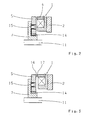
- FIG. 3 shown embodiment of an electromagnetically actuated brake according to the prior art differs from the exemplary embodiment Fig. 2 in that the brake is designed as a positive brake;
- the armature disk 5 and the magnetic body 1 each have a front teeth 16 and 17, respectively.
- a preferred embodiment of the invention comprises an electromagnetically actuated brake rotatably connected to a first fixed member 2 magnetic body 1 with a coil having a first friction surface 3 and a second component to be braked 11 (usually the component 11 is a shaft to be braked) by means of an outer cone 9 and a clamping ring 10 having clamping element 8 rotatably connected hub.
- a first fixed member 2 magnetic body 1 with a coil having a first friction surface 3 and a second component to be braked 11 (usually the component 11 is a shaft to be braked) by means of an outer cone 9 and a clamping ring 10 having clamping element 8 rotatably connected hub.
- the hub 7, a friction surface 3 of the magnetic body facing the friction surface 13, wherein the magnetic body 1 against the force of a spring element, preferably a diaphragm spring 6 in the direction of the hub 7 is designed to be axially movable.
- the torque is transmitted via the diaphragm spring 6 to the first stationary component 2, which is, for example, a housing.
- the hub 7 is integral with the outer cone 9 of the clamping element 8, so that advantageously one component is less required.
- the rotationally fixed with the braked shaft 11 and axially fixed hub 7 has a friction surface 13;
- the magnetic body 1 is rotatably connected via a driving profile 14 with the first stationary component 2 and axially displaceable, wherein in the non-energized state of the brake, a return spring 15 causes the opening of the brake.
- FIG. 6 illustrated embodiment of an electromagnetically actuated brake according to the invention differs from the exemplary embodiment Fig. 5 in that the brake as a positive brake is executed, wherein the hub 7 and the magnetic body 1 each have a front teeth 16 and 17 respectively.
Landscapes
- Engineering & Computer Science (AREA)
- General Engineering & Computer Science (AREA)
- Mechanical Engineering (AREA)
- Braking Arrangements (AREA)
Claims (7)
- Frein à actionnement électromagnétique, comportant un corps magnétique (1) relié de manière solidaire en rotation à un premier composant fixe (2), lequel corps magnétique comprend une première surface de frottement (3) ou une denture droite (17), et un moyeu (7) relié de manière solidaire en rotation à un deuxième composant (11) devant être freiné, lequel moyeu sert de blindage magnétique pour le corps magnétique, caractérisé en ce que le moyeu (7) comprend une surface de frottement (13) ou une denture droite (16) tournée vers la surface de frottement (3) ou la denture droite (17) du corps magnétique (1), et en ce que le corps magnétique (1) est réalisé de manière axialement mobile en direction du moyeu (7), et en ce que, lors de l'alimentation en courant électrique du corps magnétique, une force de traction axiale agit sur le corps magnétique pour fermer le frein.
- Frein à actionnement électromagnétique selon la revendication 1, caractérisé en ce que le corps magnétique (1) est réalisé de manière axialement mobile sur le moyeu (7), à l'encontre de la force d'un élément de ressort (6).
- Frein à actionnement électromagnétique selon la revendication 1, caractérisé en ce que le corps magnétique (1) est relié de manière solidaire en rotation au premier composant (2) par l'intermédiaire d'un profil d'entraînement (14) et est disposé de manière déplaçable axialement, un ressort de rappel (15) provoquant l'ouverture du frein à l'état non alimenté en courant électrique du frein.
- Frein à actionnement électromagnétique selon la revendication 2, caractérisé en ce que l'élément de ressort (6) est réalisé sous forme de ressort à diaphragme.
- Frein à actionnement électromagnétique selon l'une quelconque des revendications précédentes, caractérisé en ce que le moyeu (7) est relié de manière solidaire en rotation au deuxième composant (11) devant être freiné, au moyen d'un élément de serrage (8) comprenant un cône extérieur (9) et une bague de serrage (10).
- Frein à actionnement électromagnétique selon la revendication 5, caractérisé en ce que le moyeu (7) est réalisé d'une seule pièce avec le cône extérieur (9) de l'élément de serrage (8).
- Frein à actionnement électromagnétique selon l'une quelconque des revendications précédentes, caractérisé en ce que le frein est maintenu fermé par un aimant permanent dans l'état non alimenté en courant électrique d'un électroaimant.
Applications Claiming Priority (2)
| Application Number | Priority Date | Filing Date | Title |
|---|---|---|---|
| DE102008054636A DE102008054636A1 (de) | 2008-12-15 | 2008-12-15 | Elektromagnetisch betätigbare Bremse |
| PCT/EP2009/065204 WO2010072467A1 (fr) | 2008-12-15 | 2009-11-16 | Frein à actionnement électromagnétique |
Publications (2)
| Publication Number | Publication Date |
|---|---|
| EP2366072A1 EP2366072A1 (fr) | 2011-09-21 |
| EP2366072B1 true EP2366072B1 (fr) | 2013-04-03 |
Family
ID=41507854
Family Applications (1)
| Application Number | Title | Priority Date | Filing Date |
|---|---|---|---|
| EP09753102A Not-in-force EP2366072B1 (fr) | 2008-12-15 | 2009-11-16 | Frein à actionnement électromagnétique |
Country Status (6)
| Country | Link |
|---|---|
| EP (1) | EP2366072B1 (fr) |
| JP (1) | JP2012512370A (fr) |
| KR (1) | KR20110097836A (fr) |
| DE (1) | DE102008054636A1 (fr) |
| TW (1) | TW201022549A (fr) |
| WO (1) | WO2010072467A1 (fr) |
Families Citing this family (2)
| Publication number | Priority date | Publication date | Assignee | Title |
|---|---|---|---|---|
| US10197141B2 (en) * | 2015-11-03 | 2019-02-05 | Metso Flow Control Usa Inc. | Electric actuator with a fail-safe mode of operation |
| CN108561457A (zh) * | 2018-05-23 | 2018-09-21 | 苏州思安吉机电设备有限公司 | 一种失电型断电自保持通电消磁制动器及直联无间隙电机 |
Family Cites Families (10)
| Publication number | Priority date | Publication date | Assignee | Title |
|---|---|---|---|---|
| JPS5136143B2 (fr) * | 1971-12-15 | 1976-10-06 | ||
| DE2638944A1 (de) | 1976-08-28 | 1978-03-02 | Zahnradfabrik Friedrichshafen | Magnetisch betaetigte reibungskupplung oder -bremse |
| US4216849A (en) * | 1978-06-12 | 1980-08-12 | Kelsey Hayes Co. | Electromagnets for brakes and clutches |
| DE3246233A1 (de) * | 1982-12-14 | 1984-06-14 | Uni-Cardan Ag, 5200 Siegburg | Vorrichtung zum uebertragen eines drehmomentes |
| JPS59100119U (ja) * | 1982-12-24 | 1984-07-06 | 友信株式会社 | 電磁ブレ−キ装置 |
| DE3805705C1 (fr) * | 1988-02-24 | 1989-06-22 | Pfaff Haushaltmaschinen Gmbh, 7500 Karlsruhe, De | |
| JP2572185Y2 (ja) * | 1993-05-10 | 1998-05-20 | 小倉クラッチ株式会社 | 電磁ディスクブレーキ |
| DE19857950A1 (de) * | 1998-12-16 | 2000-06-21 | Zahnradfabrik Friedrichshafen | Elektromotor mit einer integrierten, drehspielfreien, elektromagnetisch betätigten Bremse |
| JP4114352B2 (ja) * | 2001-12-25 | 2008-07-09 | 神鋼電機株式会社 | 電磁ブレーキ |
| JP2003247572A (ja) * | 2002-02-22 | 2003-09-05 | Miki Pulley Co Ltd | 板ばね式電磁ブレーキ装置 |
-
2008
- 2008-12-15 DE DE102008054636A patent/DE102008054636A1/de not_active Withdrawn
-
2009
- 2009-10-13 TW TW098134581A patent/TW201022549A/zh unknown
- 2009-11-16 EP EP09753102A patent/EP2366072B1/fr not_active Not-in-force
- 2009-11-16 JP JP2011541263A patent/JP2012512370A/ja active Pending
- 2009-11-16 WO PCT/EP2009/065204 patent/WO2010072467A1/fr not_active Ceased
- 2009-11-16 KR KR1020117013613A patent/KR20110097836A/ko not_active Withdrawn
Also Published As
| Publication number | Publication date |
|---|---|
| TW201022549A (en) | 2010-06-16 |
| EP2366072A1 (fr) | 2011-09-21 |
| WO2010072467A1 (fr) | 2010-07-01 |
| JP2012512370A (ja) | 2012-05-31 |
| KR20110097836A (ko) | 2011-08-31 |
| DE102008054636A1 (de) | 2010-06-17 |
Similar Documents
| Publication | Publication Date | Title |
|---|---|---|
| EP1922497B1 (fr) | Point de changement de vitesse d'une boite de vitesses pour l'etablissement d'une liaison solidaire en rotation entre une roue dentee et un arbre | |
| DE102014220414A1 (de) | Permanentmagnetbremse für eine Antriebsvorrichtung zum Verstellen eines Fahrzeugteils | |
| DE102011054348B4 (de) | Elektromagnetische Kupplung | |
| DE2747465C2 (de) | Ruhestrombetätigte Bremse | |
| DE102009028568A1 (de) | Vorrichtung zur Blockierung eines linearen Stellantriebs | |
| WO2020088873A1 (fr) | Ensemble d'embrayage pour chaîne cinématique de véhicule automobile et chaîne cinématique de véhicule automobile | |
| AT508579A1 (de) | Elektromagnetische brems- bzw. kupplungsvorrichtung | |
| EP2366072B1 (fr) | Frein à actionnement électromagnétique | |
| EP2901037B1 (fr) | Système de frein et moteur électrique équipé d'un système de frein | |
| DE4225158A1 (de) | Elektromaschinensystem | |
| DE102006024276A1 (de) | Elektromagnetisch betätigbare Einheit, insbesondere eine Kupplung/Bremse bzw. Sperre | |
| DE29510168U1 (de) | Federdruck-Zweikreisbremssystem | |
| DE102006007688B4 (de) | Elektromagnetisch betätigbare Schalteinheit | |
| EP3760892B1 (fr) | Frein à disques multiples pour dispositif d'entraînement de véhicule | |
| DE102015001442B4 (de) | Bremsanordnung mit einem Bremsbelagträger und einem Mitnehmer | |
| DE102016015242A1 (de) | Bremszange mit Freistellmechanismus | |
| DE102011004814A1 (de) | Bremseinheit | |
| DE102011006900B4 (de) | Elektromagnetische Federdruckbremse oder -kupplung | |
| DE29907942U1 (de) | Elektromagnetisch betätigte Einflächenkupplung oder Einflächenbremse | |
| DE102009051499A1 (de) | Elektromotor mit Stillstandsbremse | |
| DE102013212315B4 (de) | Verfahren zur Herstellung einer betätigbaren Kupplung | |
| CH694134A5 (de) | Elektromagnetisch betätigte Einflächenkupplung oder Einflächenbremse. | |
| DE10311385B4 (de) | Polreibungskupplung sowie Kupplungskombination | |
| DE10244018B4 (de) | Antriebseinheit | |
| EP3260722A1 (fr) | Frein et système d'entraînement comprenant un frein |
Legal Events
| Date | Code | Title | Description |
|---|---|---|---|
| PUAI | Public reference made under article 153(3) epc to a published international application that has entered the european phase |
Free format text: ORIGINAL CODE: 0009012 |
|
| 17P | Request for examination filed |
Effective date: 20110504 |
|
| AK | Designated contracting states |
Kind code of ref document: A1 Designated state(s): AT BE BG CH CY CZ DE DK EE ES FI FR GB GR HR HU IE IS IT LI LT LU LV MC MK MT NL NO PL PT RO SE SI SK SM TR |
|
| DAX | Request for extension of the european patent (deleted) | ||
| 17Q | First examination report despatched |
Effective date: 20120731 |
|
| GRAP | Despatch of communication of intention to grant a patent |
Free format text: ORIGINAL CODE: EPIDOSNIGR1 |
|
| GRAS | Grant fee paid |
Free format text: ORIGINAL CODE: EPIDOSNIGR3 |
|
| GRAA | (expected) grant |
Free format text: ORIGINAL CODE: 0009210 |
|
| AK | Designated contracting states |
Kind code of ref document: B1 Designated state(s): AT BE BG CH CY CZ DE DK EE ES FI FR GB GR HR HU IE IS IT LI LT LU LV MC MK MT NL NO PL PT RO SE SI SK SM TR |
|
| REG | Reference to a national code |
Ref country code: GB Ref legal event code: FG4D Free format text: NOT ENGLISH |
|
| REG | Reference to a national code |
Ref country code: CH Ref legal event code: EP Ref country code: AT Ref legal event code: REF Ref document number: 604927 Country of ref document: AT Kind code of ref document: T Effective date: 20130415 |
|
| REG | Reference to a national code |
Ref country code: IE Ref legal event code: FG4D Free format text: LANGUAGE OF EP DOCUMENT: GERMAN |
|
| REG | Reference to a national code |
Ref country code: DE Ref legal event code: R096 Ref document number: 502009006725 Country of ref document: DE Effective date: 20130529 |
|
| PG25 | Lapsed in a contracting state [announced via postgrant information from national office to epo] |
Ref country code: SI Free format text: LAPSE BECAUSE OF FAILURE TO SUBMIT A TRANSLATION OF THE DESCRIPTION OR TO PAY THE FEE WITHIN THE PRESCRIBED TIME-LIMIT Effective date: 20130403 |
|
| REG | Reference to a national code |
Ref country code: NL Ref legal event code: VDEP Effective date: 20130403 |
|
| REG | Reference to a national code |
Ref country code: LT Ref legal event code: MG4D |
|
| PG25 | Lapsed in a contracting state [announced via postgrant information from national office to epo] |
Ref country code: ES Free format text: LAPSE BECAUSE OF FAILURE TO SUBMIT A TRANSLATION OF THE DESCRIPTION OR TO PAY THE FEE WITHIN THE PRESCRIBED TIME-LIMIT Effective date: 20130714 Ref country code: LT Free format text: LAPSE BECAUSE OF FAILURE TO SUBMIT A TRANSLATION OF THE DESCRIPTION OR TO PAY THE FEE WITHIN THE PRESCRIBED TIME-LIMIT Effective date: 20130403 Ref country code: PT Free format text: LAPSE BECAUSE OF FAILURE TO SUBMIT A TRANSLATION OF THE DESCRIPTION OR TO PAY THE FEE WITHIN THE PRESCRIBED TIME-LIMIT Effective date: 20130805 Ref country code: NO Free format text: LAPSE BECAUSE OF FAILURE TO SUBMIT A TRANSLATION OF THE DESCRIPTION OR TO PAY THE FEE WITHIN THE PRESCRIBED TIME-LIMIT Effective date: 20130703 Ref country code: GR Free format text: LAPSE BECAUSE OF FAILURE TO SUBMIT A TRANSLATION OF THE DESCRIPTION OR TO PAY THE FEE WITHIN THE PRESCRIBED TIME-LIMIT Effective date: 20130704 Ref country code: IS Free format text: LAPSE BECAUSE OF FAILURE TO SUBMIT A TRANSLATION OF THE DESCRIPTION OR TO PAY THE FEE WITHIN THE PRESCRIBED TIME-LIMIT Effective date: 20130803 Ref country code: FI Free format text: LAPSE BECAUSE OF FAILURE TO SUBMIT A TRANSLATION OF THE DESCRIPTION OR TO PAY THE FEE WITHIN THE PRESCRIBED TIME-LIMIT Effective date: 20130403 Ref country code: NL Free format text: LAPSE BECAUSE OF FAILURE TO SUBMIT A TRANSLATION OF THE DESCRIPTION OR TO PAY THE FEE WITHIN THE PRESCRIBED TIME-LIMIT Effective date: 20130403 Ref country code: SE Free format text: LAPSE BECAUSE OF FAILURE TO SUBMIT A TRANSLATION OF THE DESCRIPTION OR TO PAY THE FEE WITHIN THE PRESCRIBED TIME-LIMIT Effective date: 20130403 |
|
| PG25 | Lapsed in a contracting state [announced via postgrant information from national office to epo] |
Ref country code: PL Free format text: LAPSE BECAUSE OF FAILURE TO SUBMIT A TRANSLATION OF THE DESCRIPTION OR TO PAY THE FEE WITHIN THE PRESCRIBED TIME-LIMIT Effective date: 20130403 Ref country code: CY Free format text: LAPSE BECAUSE OF FAILURE TO SUBMIT A TRANSLATION OF THE DESCRIPTION OR TO PAY THE FEE WITHIN THE PRESCRIBED TIME-LIMIT Effective date: 20130403 Ref country code: BG Free format text: LAPSE BECAUSE OF FAILURE TO SUBMIT A TRANSLATION OF THE DESCRIPTION OR TO PAY THE FEE WITHIN THE PRESCRIBED TIME-LIMIT Effective date: 20130703 Ref country code: LV Free format text: LAPSE BECAUSE OF FAILURE TO SUBMIT A TRANSLATION OF THE DESCRIPTION OR TO PAY THE FEE WITHIN THE PRESCRIBED TIME-LIMIT Effective date: 20130403 Ref country code: HR Free format text: LAPSE BECAUSE OF FAILURE TO SUBMIT A TRANSLATION OF THE DESCRIPTION OR TO PAY THE FEE WITHIN THE PRESCRIBED TIME-LIMIT Effective date: 20130403 |
|
| PG25 | Lapsed in a contracting state [announced via postgrant information from national office to epo] |
Ref country code: EE Free format text: LAPSE BECAUSE OF FAILURE TO SUBMIT A TRANSLATION OF THE DESCRIPTION OR TO PAY THE FEE WITHIN THE PRESCRIBED TIME-LIMIT Effective date: 20130403 Ref country code: CZ Free format text: LAPSE BECAUSE OF FAILURE TO SUBMIT A TRANSLATION OF THE DESCRIPTION OR TO PAY THE FEE WITHIN THE PRESCRIBED TIME-LIMIT Effective date: 20130403 Ref country code: DK Free format text: LAPSE BECAUSE OF FAILURE TO SUBMIT A TRANSLATION OF THE DESCRIPTION OR TO PAY THE FEE WITHIN THE PRESCRIBED TIME-LIMIT Effective date: 20130403 Ref country code: SK Free format text: LAPSE BECAUSE OF FAILURE TO SUBMIT A TRANSLATION OF THE DESCRIPTION OR TO PAY THE FEE WITHIN THE PRESCRIBED TIME-LIMIT Effective date: 20130403 |
|
| PGFP | Annual fee paid to national office [announced via postgrant information from national office to epo] |
Ref country code: FR Payment date: 20131108 Year of fee payment: 5 |
|
| PLBE | No opposition filed within time limit |
Free format text: ORIGINAL CODE: 0009261 |
|
| STAA | Information on the status of an ep patent application or granted ep patent |
Free format text: STATUS: NO OPPOSITION FILED WITHIN TIME LIMIT |
|
| PG25 | Lapsed in a contracting state [announced via postgrant information from national office to epo] |
Ref country code: RO Free format text: LAPSE BECAUSE OF FAILURE TO SUBMIT A TRANSLATION OF THE DESCRIPTION OR TO PAY THE FEE WITHIN THE PRESCRIBED TIME-LIMIT Effective date: 20130403 |
|
| PGFP | Annual fee paid to national office [announced via postgrant information from national office to epo] |
Ref country code: IT Payment date: 20131112 Year of fee payment: 5 |
|
| 26N | No opposition filed |
Effective date: 20140106 |
|
| REG | Reference to a national code |
Ref country code: DE Ref legal event code: R097 Ref document number: 502009006725 Country of ref document: DE Effective date: 20140106 |
|
| BERE | Be: lapsed |
Owner name: ZF FRIEDRICHSHAFEN A.G. Effective date: 20131130 |
|
| REG | Reference to a national code |
Ref country code: CH Ref legal event code: PL |
|
| GBPC | Gb: european patent ceased through non-payment of renewal fee |
Effective date: 20131116 |
|
| PG25 | Lapsed in a contracting state [announced via postgrant information from national office to epo] |
Ref country code: LI Free format text: LAPSE BECAUSE OF NON-PAYMENT OF DUE FEES Effective date: 20131130 Ref country code: MC Free format text: LAPSE BECAUSE OF FAILURE TO SUBMIT A TRANSLATION OF THE DESCRIPTION OR TO PAY THE FEE WITHIN THE PRESCRIBED TIME-LIMIT Effective date: 20130403 Ref country code: CH Free format text: LAPSE BECAUSE OF NON-PAYMENT OF DUE FEES Effective date: 20131130 |
|
| REG | Reference to a national code |
Ref country code: IE Ref legal event code: MM4A |
|
| PGFP | Annual fee paid to national office [announced via postgrant information from national office to epo] |
Ref country code: DE Payment date: 20131113 Year of fee payment: 5 |
|
| PG25 | Lapsed in a contracting state [announced via postgrant information from national office to epo] |
Ref country code: BE Free format text: LAPSE BECAUSE OF NON-PAYMENT OF DUE FEES Effective date: 20131130 |
|
| PG25 | Lapsed in a contracting state [announced via postgrant information from national office to epo] |
Ref country code: IE Free format text: LAPSE BECAUSE OF NON-PAYMENT OF DUE FEES Effective date: 20131116 |
|
| PG25 | Lapsed in a contracting state [announced via postgrant information from national office to epo] |
Ref country code: GB Free format text: LAPSE BECAUSE OF NON-PAYMENT OF DUE FEES Effective date: 20131116 |
|
| PG25 | Lapsed in a contracting state [announced via postgrant information from national office to epo] |
Ref country code: SM Free format text: LAPSE BECAUSE OF FAILURE TO SUBMIT A TRANSLATION OF THE DESCRIPTION OR TO PAY THE FEE WITHIN THE PRESCRIBED TIME-LIMIT Effective date: 20130403 |
|
| REG | Reference to a national code |
Ref country code: DE Ref legal event code: R119 Ref document number: 502009006725 Country of ref document: DE |
|
| PG25 | Lapsed in a contracting state [announced via postgrant information from national office to epo] |
Ref country code: TR Free format text: LAPSE BECAUSE OF FAILURE TO SUBMIT A TRANSLATION OF THE DESCRIPTION OR TO PAY THE FEE WITHIN THE PRESCRIBED TIME-LIMIT Effective date: 20130403 |
|
| PG25 | Lapsed in a contracting state [announced via postgrant information from national office to epo] |
Ref country code: MK Free format text: LAPSE BECAUSE OF FAILURE TO SUBMIT A TRANSLATION OF THE DESCRIPTION OR TO PAY THE FEE WITHIN THE PRESCRIBED TIME-LIMIT Effective date: 20130403 Ref country code: HU Free format text: LAPSE BECAUSE OF FAILURE TO SUBMIT A TRANSLATION OF THE DESCRIPTION OR TO PAY THE FEE WITHIN THE PRESCRIBED TIME-LIMIT; INVALID AB INITIO Effective date: 20091116 Ref country code: LU Free format text: LAPSE BECAUSE OF NON-PAYMENT OF DUE FEES Effective date: 20131116 |
|
| REG | Reference to a national code |
Ref country code: FR Ref legal event code: ST Effective date: 20150731 |
|
| PG25 | Lapsed in a contracting state [announced via postgrant information from national office to epo] |
Ref country code: MT Free format text: LAPSE BECAUSE OF FAILURE TO SUBMIT A TRANSLATION OF THE DESCRIPTION OR TO PAY THE FEE WITHIN THE PRESCRIBED TIME-LIMIT Effective date: 20130403 |
|
| PG25 | Lapsed in a contracting state [announced via postgrant information from national office to epo] |
Ref country code: DE Free format text: LAPSE BECAUSE OF NON-PAYMENT OF DUE FEES Effective date: 20150602 |
|
| PG25 | Lapsed in a contracting state [announced via postgrant information from national office to epo] |
Ref country code: FR Free format text: LAPSE BECAUSE OF NON-PAYMENT OF DUE FEES Effective date: 20141201 |
|
| PG25 | Lapsed in a contracting state [announced via postgrant information from national office to epo] |
Ref country code: IT Free format text: LAPSE BECAUSE OF NON-PAYMENT OF DUE FEES Effective date: 20141116 |
|
| REG | Reference to a national code |
Ref country code: AT Ref legal event code: MM01 Ref document number: 604927 Country of ref document: AT Kind code of ref document: T Effective date: 20141116 |
|
| PG25 | Lapsed in a contracting state [announced via postgrant information from national office to epo] |
Ref country code: AT Free format text: LAPSE BECAUSE OF NON-PAYMENT OF DUE FEES Effective date: 20141116 |