EP2366489B1 - Vorrichtung zum Einpressen von Isolierstegen - Google Patents
Vorrichtung zum Einpressen von Isolierstegen Download PDFInfo
- Publication number
- EP2366489B1 EP2366489B1 EP20110158218 EP11158218A EP2366489B1 EP 2366489 B1 EP2366489 B1 EP 2366489B1 EP 20110158218 EP20110158218 EP 20110158218 EP 11158218 A EP11158218 A EP 11158218A EP 2366489 B1 EP2366489 B1 EP 2366489B1
- Authority
- EP
- European Patent Office
- Prior art keywords
- roller
- rollers
- insulating
- pressing
- frame profile
- Prior art date
- Legal status (The legal status is an assumption and is not a legal conclusion. Google has not performed a legal analysis and makes no representation as to the accuracy of the status listed.)
- Not-in-force
Links
- 238000003825 pressing Methods 0.000 title claims description 13
- 239000002131 composite material Substances 0.000 claims description 6
- 229910052782 aluminium Inorganic materials 0.000 claims description 3
- XAGFODPZIPBFFR-UHFFFAOYSA-N aluminium Chemical compound [Al] XAGFODPZIPBFFR-UHFFFAOYSA-N 0.000 claims description 3
- 238000004519 manufacturing process Methods 0.000 claims description 2
- 229910052751 metal Inorganic materials 0.000 description 9
- 239000002184 metal Substances 0.000 description 9
- 238000010276 construction Methods 0.000 description 4
- 238000000034 method Methods 0.000 description 4
- 238000009413 insulation Methods 0.000 description 3
- 238000005096 rolling process Methods 0.000 description 3
- 239000000463 material Substances 0.000 description 2
- 238000005452 bending Methods 0.000 description 1
- 239000000969 carrier Substances 0.000 description 1
- 230000006866 deterioration Effects 0.000 description 1
- 238000011161 development Methods 0.000 description 1
- 230000018109 developmental process Effects 0.000 description 1
- 238000005516 engineering process Methods 0.000 description 1
Images
Classifications
-
- B—PERFORMING OPERATIONS; TRANSPORTING
- B23—MACHINE TOOLS; METAL-WORKING NOT OTHERWISE PROVIDED FOR
- B23P—METAL-WORKING NOT OTHERWISE PROVIDED FOR; COMBINED OPERATIONS; UNIVERSAL MACHINE TOOLS
- B23P11/00—Connecting or disconnecting metal parts or objects by metal-working techniques not otherwise provided for
- B23P11/005—Connecting or disconnecting metal parts or objects by metal-working techniques not otherwise provided for by expanding or crimping
-
- E—FIXED CONSTRUCTIONS
- E06—DOORS, WINDOWS, SHUTTERS, OR ROLLER BLINDS IN GENERAL; LADDERS
- E06B—FIXED OR MOVABLE CLOSURES FOR OPENINGS IN BUILDINGS, VEHICLES, FENCES OR LIKE ENCLOSURES IN GENERAL, e.g. DOORS, WINDOWS, BLINDS, GATES
- E06B3/00—Window sashes, door leaves, or like elements for closing wall or like openings; Layout of fixed or moving closures, e.g. windows in wall or like openings; Features of rigidly-mounted outer frames relating to the mounting of wing frames
- E06B3/04—Wing frames not characterised by the manner of movement
- E06B3/263—Frames with special provision for insulation
- E06B3/273—Frames with special provision for insulation with prefabricated insulating elements held in position by deformation of portions of the metal frame members
Definitions
- the present invention relates to a device for pressing insulating bars in frame profiles according to the preamble of claim 1.
- a device for pressing insulating bars in frame profiles according to the preamble of claim 1. is known from DE 75 37 337 U known.
- the invention relates to a device for pressing in insulating strips in groove strips of a frame profile, in particular an aluminum frame profile, in the production of composite profiles, wherein the device comprises a first roller having an axis of rotation.
- the publication DE 75 37 337 U relates to a thermally insulated composite profile, in particular for windows, doors or facades, consisting of two metal shells, which are held apart from each other and connected to each other via two insulating rods inserted in grooves of the metal shells. It is provided that the Nutinnenstege are formed over a mandrel in recesses of the insulating rods, which extend these recesses of the insulating rods over the entire length of the insulating rods. The mandrel is guided through the inner chamber of the composite profile and is supported on the groove webs to be deformed.
- the publication EP 0 082 468 A1 relates to a method and an apparatus for producing a thermally insulated composite profile for windows, doors or the like.
- Two extruded metal profiles made of light metal are used Clamped distance from each other and connected in terms of deformation technology with two equally spaced insulating bars.
- Each hammerhead-like edge of both insulating bars is bounded by groove strips of the metal profiles, wherein an inner Nutologicalncru against an insulating rod and an outer Nutologicalncru against the other insulating rod simultaneously, so be deformed in one process step.
- the publication EP 0 311 850 A2 relates to a composite profile, in particular for windows, doors and facades, in which two metal profiles are connected via at least one engaging in grooves between legs of the metal profiles insulating profile at a distance from each other.
- the insulating profile has at least one formed by different thicknesses of material, extending in the longitudinal direction of the wave profile on the engagement in grooves of the metal profiles certain areas.
- frame profiles of two spaced apart frame profile parts In particular, these are usually frame profile parts which have an outer profile chamber and an inner profile chamber which are connected to one another via insulating webs.
- the insulating strips engage in so-called groove strips, which are formed on the sides of the frame profile parts.
- the deformation of the groove strips is carried out in the known from the prior art method by a roller. This is moved with a predetermined contact force over the Nutolinn to bend selbige in the direction of the insulating bar and to enclose the insulating bar so. It is therefore necessary that the rolling device can penetrate into the space of the outside frame profile parts in order to contact and deform the groove strips.
- a disadvantage of these conventional, known from the prior art devices for pressing in insulating webs results from the complexity of today's metal frame profile parts. These can vary depending on the application be made very angled and have corner areas with the smallest dimensions. For this reason, it is often not possible with the known rolling devices to construct insulating bars with optimal width, since the pressing is possible only at easily accessible areas of the space of the frame profile parts. This creates a loss of space that could be used for the insulating bars, which means less heat insulation.
- the present invention has for its object to provide a device for pressing in insulating webs, which is designed such that a pressing in of the groove strips is also made possible in corner regions of the frame profile construction. Furthermore, it is an object of the invention to provide such a device which can be adapted with little effort to a known from the prior art roller.
- the device according to the invention is characterized by at least one roller carrier, which can be connected to the rotation axis of the first roller and is designed to accommodate at least one second roller, which has a smaller diameter than the first roller.
- the invention provides that the at least one roller carrier receives at least two second rollers and is designed so that the at least two second rollers are in contact with the first roller.
- the roller carrier and the two second rollers are stably mounted on the first roller. Through the contact beyond the rotational movement of the first roller can be used to drive the at least two second rollers.
- the two second rollers are movable on a different plane than the first roller in order to prevent deterioration of the running properties of the deformation device.
- the at least two second rollers have a different diameter in order to allow a sequential deformation of the groove strips.
- deformation work which is to be used in deformation of the groove strips
- the deformation process can be divided into individual steps, whereby a reduced force for bending the groove strip is required, which also has a gentle effect on the material of the groove strips.
- second roller which first comes into contact with the groove strips, have a smaller diameter in order to deform the groove strip only to a certain extent.
- the device according to the invention for pressing in insulating webs of the roller carrier is designed such that a first of the At least two second rollers in front of the first roller and a second of the at least two second rollers is positioned behind the first roller, in order to be able to distribute the contact pressure of the first roller evenly on the two second rollers in this way.
- a respective second roller before and behind the first roller it is possible to distribute the contact pressure of the first roller uniformly on the at least two second rollers.
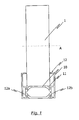
- Fig. 1 shows a section through a common frame profile 12, as is known in the art.
- the frame profile 12 has two opposite sections with an outside profile chamber 12a and an inside profile chamber 12b.
- a first roller 1 penetrates into the intermediate space of the two subregions of the frame profile 12 in order to deform the groove strip 11 in such a way that the insulating web 10 is connected without play to the latter.
- the groove strips 11 must be directly exposed below the first roller.
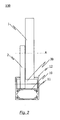
- a roller carrier 2 is provided on the side of the first roller 1.
- a roller support 2 it is also conceivable to attach a roller support 2 to both sides of the first roller 1.
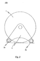
- Such a roller carrier is in Fig. 3 shown in more detail in a side view. It is mounted on the axis of rotation A of the first roll 1 and in this embodiment receives two second rolls 3a, 3b. It should be noted, however, that it does not necessarily have to be two second rollers, but rather it is also conceivable to provide only one or more than two second rollers.
- the second rollers 3a, 3b have a smaller diameter than the first roller 1. Accordingly, it is possible to reach and deform non-exposed groove strips 11. Consequently, as can be seen from a comparison of FIGS. 1 and 2 Immediately apparent, a wider insulating 10 is introduced or the frame section 12 are made narrower.
- the profile chambers 12a, 12b are replaced by Isolierstege 10.
- Fig. 3 further shows that the rollers 3a, 3b of the roller carrier can be in contact with the first roller 1. This is the stability of the entire device useful, but in this case, of course, the contact of the first roller 1 with the insulating webs 10 must be avoided, otherwise it comes to hindering the rolling movement of the rollers.
- rollers 3a, 3b in such a way that they are not in contact with the first roller 1.
- all the rollers could be arranged to be movable in one plane.
Landscapes
- Engineering & Computer Science (AREA)
- Mechanical Engineering (AREA)
- Wing Frames And Configurations (AREA)
- Casting Or Compression Moulding Of Plastics Or The Like (AREA)
Description
- Die vorliegende Erfindung betrifft eine Vorrichtung zum Einpressen von Isolierstegen in Rahmenprofile nach dem Oberbegriff des Patentanspruches 1. Eine solche Vorrichtung ist aus der
DE 75 37 337 U bekannt. - Demgemäß betrifft die Erfindung eine Vorrichtung zum Einpressen von Isolierstegen in Nutleisten eines Rahmenprofils, insbesondere eines Aluminium-Rahmenprofils, bei der Herstellung von Verbundprofilen, wobei die Vorrichtung eine erste Walze mit einer Rotationsachse aufweist.
- Die Druckschrift
DE 75 37 337 U betrifft ein wärmegedämmtes Verbundprofil, insbesondere für Fenster, Türen oder Fassaden, bestehend aus zwei Metallschalen, die im Abstand voneinander gehalten und über zwei in Nuten der Metallschalen eingesetzte Isolierstäbe miteinander verbunden sind. Dabei ist vorgesehen, dass die Nutinnenstege über einen Dorn in Aussparungen der Isolierstäbe eingeformt werden, wobei sich diese Aussparungen der Isolierstäbe über die gesamte Länge der Isolierstäbe erstrecken. Der Dorn wird durch die Innenkammer des Verbundprofils geführt und stützt sich an den zu verformenden Nutstegen ab. - Die Druckschrift
EP 0 082 468 A1 betrifft ein Verfahren sowie eine Vorrichtung zur Herstellung eines wärmegedämmten Verbundprofils für Fenster, Türen oder dergleichen. Dabei werden zwei strangepresste Metallprofile aus Leichtmetall in Distanz zueinander festgespannt und mit zwei ebenfalls voneinander distanzierten Isolierstäben verformungstechnisch verbunden. Jeder hammerkopfartig ausgebildete Rand beider Isolierstäbe wird von Nutleisten der Metallprofile begrenzt, wobei ein innen liegendes Nutleistenpaar gegen den einen Isolierstab und ein außen liegendes Nutleistenpaar gegen den anderen Isolierstab gleichzeitig, also in einem Verfahrensgang verformt werden. - Die Druckschrift
EP 0 311 850 A2 betrifft ein Verbundprofil, insbesondere für Fenster, Türen und Fassaden, bei welchen zwei Metallprofile über mindestens ein in Nuten zwischen Schenkeln der Metallprofile eingreifendes Isolierprofil in Abstand voneinander verbunden sind. Das Isolierprofil weist mindestens ein durch unterschiedliche Materialdicken gebildetes, in Längsrichtung verlaufendes Wellenprofil am zum Eingriff in Nuten der Metallprofile bestimmte Bereiche auf. - Zur Wärmeisolation von Fenster- und Türrahmen ist es bekannt, Rahmenprofile aus zwei voneinander beabstandeten Rahmenprofilteilen herzustellen. Insbesondere handelt es sich dabei gewöhnlich um Rahmenprofilteile, welche eine außenseitige Profilkammer sowie eine innenseitige Profilkammer, welche über Isolierstege miteinander verbunden sind, aufweisen. Um die Isolierstege mit den Rahmenprofilteilen kraftschlüssig verbinden zu können, greifen die Isolierstege in sogenannte Nutleisten ein, welche an den Seiten der Rahmenprofilteile gebildet sind. Sobald die Isolierstege in einem ersten Schritt mit etwas Spiel in die Nutleisten eingeführt worden sind, werden die Nutleisten in einem nächsten Schritt durch mechanische Krafteinwirkung zusammengepresst und die Isolierstege in ihrer Position fixiert.
- Die Verformung der Nutleisten wird bei dem aus dem Stand der Technik bekannten Verfahren durch eine Walze ausgeführt. Diese wird mit einer vorbestimmten Anpresskraft über die Nutleisten bewegt, um selbige in Richtung des Isolierstegs zu verbiegen und den Isoliersteg damit einzuschließen. Es ist demnach erforderlich, dass die Walzvorrichtung in den Zwischenraum der außenseitigen Rahmenprofilteile eindringen kann, um die Nutleisten zu kontaktieren und verformen zu können.
- Ein Nachteil dieser herkömmlichen, aus dem Stand der Technik bekannten Vorrichtungen zum Einpressen von Isolierstegen resultiert aus der Komplexität der heutigen Metall-Rahmenprofilteile. Diese können je nach Anwendungsgebiet sehr verwinkelt ausgeführt sein und über Eckbereiche mit kleinsten Dimensionen verfügen. Aus diesem Grund gelingt es mit den bekannten Walzvorrichtungen oftmals nicht, Isolierstege mit optimaler Breite zu konstruieren, da das Einpressen nur an leicht zugänglichen Bereichen des Zwischenraums der Rahmprofilteile möglich ist. Hierdurch entsteht ein Verlust an Raum, welcher für die Isolierstege genutzt werden könnte, was eine geringere Wärmedämmung bedeutet.
- Auf Grundlage dieser Problemstellung liegt der vorliegenden Erfindung die Aufgabe zugrunde, eine Vorrichtung zum Einpressen von Isolierstegen anzugeben, die derart ausgebildet ist, dass ein Einpressen der Nutleisten auch in Eckbereichen der Rahmenprofilkonstruktion ermöglicht wird. Ferner ist es eine Aufgabe der Erfindung, eine derartige Vorrichtung anzugeben, welche mit wenig Aufwand an eine aus dem Stand der Technik bekannte Walze adaptierbar ist.
- Diese Aufgaben werden erfindungsgemäß durch den Gegenstand des unabhängigen Patentanspruches 1 gelöst. Vorteilhafte Weiterbildungen sind in den Unteransprüchen angegeben.
- Die erfindungsgemäße Vorrichtung zeichnet sich durch mindestens einen Walzenträger aus, welcher mit der Rotationsachse der ersten Walze verbindbar und ausgebildet ist, mindestens eine zweite Walze, welche einen kleineren Durchmesser als die erste Walze aufweist, aufzunehmen.
- Durch den oben genannten Lösungsansatz ergibt sich eine Vielzahl von Vorteilen gegenüber dem bisherigen Stand der Technik. So können mit der erfindungsgemäßen Lösung Rahmenprofile mit verbreiterten Isolierstegen hergestellt werden. Daraus resultieren entsprechend höhere Wärmedämmeigenschaften der Rahmenprofilkonstruktion. Alternativ ist es selbstverständlich auch denkbar, die Größe der Isolierstege beizubehalten und unter besserer Ausnutzung des Zwischenraums schmälere Rahmenprofile herzustellen. Ferner werden durch die Erfindung im Vergleich zu herkömmlichen Lösungen geringere Mengen an Aluminium für die Konstruktion der Rahmenprofile benötigt, da größere Bereiche der Rahmenprofilkonstruktion mit Isolierstegen versehen werden können. Da die erfindungsgemäße Lösung problemlos auf die aus dem Stand der Technik bekannte Lösung übertragen werden kann, ist es weiterhin möglich herkömmliche Walzen einfach und kostengünstig nachzurüsten.
- Bei der Vorrichtung zum Einpressen von Isolierstegen ist erfindungsgemäß vorgesehen, dass der mindestens eine Walzenträger mindestens zwei zweite Walzen aufnimmt und ausgebildet ist, dass die mindestens zwei zweiten Walzen in Kontakt mit der ersten Walze stehen. Mit dieser Ausführungsvariante wird erreicht, dass der Walzenträger sowie die beiden zweiten Walzen stabil an der ersten Walze angebracht sind. Durch den Kontakt kann darüber hinaus die Rotationsbewegung der ersten Walze dazu genutzt werden, die mindestens zwei zweiten Walzen anzutreiben. Selbstverständlich sind dabei die beiden zweiten Walzen auf einer anderen Ebene bewegbar als die erste Walze, um eine Verschlechterung der Laufeigenschaften der Verformungsvorrichtung zu verhindern.
- Gemäß einer Ausführungsform ist es vorgesehen, dass die mindestens zwei zweiten Walzen einen unterschiedlichen Durchmesser aufweisen, um ein sequentielles Verformen der Nutleisten zu ermöglichen. Der Vorteil dieser Alternative liegt darin, dass Verformungsarbeit, welche bei Verformung der Nutleisten aufzuwenden ist, auf mehrere (mindestens zwei) zweite Walzen aufgeteilt werden kann. Dadurch kann der Verformungsvorgang in einzelne Schritte unterteilt werden, wodurch eine verringerte Kraft zum Verbiegen der Nutleiste benötigt wird, was sich ferner schonend auf das Material der Nutleisten auswirkt. Beispielsweise kann dazu diejenige zweite Walze, welche zuerst in Kontakt mit den Nutleisten kommt, einen kleineren Durchmesser aufweisen, um die Nutleiste nur zu einem gewissen Teil zu verformen.
- Nach einer weiteren Umsetzung der erfindungsgemäßen Vorrichtung zum Einpressen von Isolierstegen ist der Walzenträger derart ausgebildet ist, dass eine erste der mindestens zwei zweiten Walzen vor der ersten Walze und eine zweite der mindestens zwei zweiten Walzen hinter der ersten Walze positioniert ist, um auf diese Weise die Anpresskraft der ersten Walze auf die zwei zweiten Walzen gleichmäßig verteilen zu können. Durch das Anbringen je einer zweiten Walze vor und hinter der ersten Walze ist es möglich, den Anpressdruck der ersten Walze gleichmäßig auf die mindestens zwei zweiten Walzen zu verteilen.
- Im Folgenden wird ein bevorzugtes Ausführungsbeispiel der Erfindung anhand der Zeichnungen näher erläutert.
- Es zeigen:
- Fig. 1
- eine Schnittansicht durch ein Rahmenprofil mit einer aus dem Stand der Technik bekannten Vorrichtung zum Einpressen von Isolierstegen;
- Fig. 2
- eine Schnittansicht durch ein Rahmenprofil mit schematischer Darstellung einer erfindungsgemäßen Vorrichtung zum Einpressen von Isolierstegen; und
- Fig. 3
- eine Seitenansicht der Ausführungsform gemäß
Fig. 2 . -
Fig. 1 zeigt einen Schnitt durch ein gewöhnliches Rahmenprofil 12, wie es aus dem Stand der Technik bekannt ist. Das Rahmenprofil 12 weist zwei gegenüberliegende Teilbereiche mit einer außenseitigen Profilkammer 12a sowie einer innenseitigen Profilkammer 12b auf. Eine erste Walze 1 dringt dabei in den Zwischenraum der beiden Teilbereiche des Rahmenprofils 12 ein um die Nutleiste 11 derart zu verformen, dass der Isoliersteg 10 spielfrei mit dieser verbunden wird. Dabei müssen die Nutleisten 11 direkt freiliegend unterhalb der ersten Walze angebracht sein. - Wie in
Fig. 2 gezeigt, werden mit der erfindungsgemäßen Vorrichtung auch nicht freiliegende Bereiche des Rahmenprofils 12 erreicht. Dazu ist ein Walzenträger 2 an der Seite der ersten Walze 1 vorgesehen. Selbstverständlich ist es auch denkbar, an beide Seiten der ersten Walze 1 einen Walzenträger 2 anzubringen. - Ein solcher Walzenträger ist in
Fig. 3 in einer Seitenansicht genauer dargestellt. Er ist an der Rotationsachse A der ersten Walze 1 angebracht und nimmt in dieser Ausführungsform zwei zweite Walzen 3a, 3b auf. Es sei jedoch erwähnt, dass es sich nicht zwangsweise um zwei zweite Walzen handeln muss, vielmehr ist es auch vorstellbar nur eine oder mehr als zwei zweite Walzen vorzusehen. Die zweiten Walzen 3a, 3b weisen einen kleineren Durchmesser als die erste Walze 1 auf. Dementsprechend ist es möglich, nicht freiliegende Nutleisten 11 zu erreichen und zu verformen. Folglich kann, wie aus einem Vergleich derFiguren 1 und2 sofort ersichtlich wird, ein breiterer Isoliersteg 10 eingebracht oder das Rahmenprofil 12 schmäler ausgestaltet werden. Im Einzelnen können, wie in der Ausführungsform nachFig. 2 dargestellt, die Profilkammern 12a, 12b durch Isolierstege 10 ersetzt werden. -
Fig. 3 zeigt weiterhin, dass die Walzen 3a, 3b des Walzenträgers in Kontakt mit der ersten Walze 1 stehen können. Dies ist der Stabilität der gesamten Vorrichtung dienlich, jedoch muss in diesem Fall selbstverständlich der Kontakt der ersten Walze 1 mit den Isolierstegen 10 vermieden werden, da es sonst zur Hinderung der Rollbewegung der Walzen kommt. - Es ist selbstverständlich ebenfalls möglich, die Walzen 3a, 3b derart auszugestalten, dass diese nicht in Kontakt mit der ersten Walze 1 stehen. In diesem Fall könnten dementsprechend auch alle Walzen in einer Ebene bewegbar angeordnet werden.
-
- 1
- erste Walze
- 2
- Walzenträger
- 3a, 3b
- zweite Walzen
- 10
- Isoliersteg
- 11
- Nutleiste
- 12
- Rahmenprofil
- 12a
- außenseitige Profilkammer
- 12b
- innenseitige Profilkammer
Claims (3)
- Vorrichtung (100) zum Einpressen von Isolierstegen (10) in Nutleisten (11) eines Rahmenprofils (12), insbesondere Aluminium-Rahmenprofils bei der Herstellung von Verbundprofilen, wobei die Vorrichtung (100) eine erste Walze (1) mit einer Rotationsachse (A) aufweist, wobei die Vorrichtung (100) mindestens einen Walzenträger (2) aufweist, welcher mit der Rotationsachse (A) der ersten Walze (1) verbindbar und ausgebildet ist, mindestens eine zweite Walze (3a, 3b) aufzunehmen, welche einen kleineren Durchmesser als die erste Walze (1) aufweist,
dadurch gekennzeichnet, dass
der mindestens eine Walzenträger (2) mindestens zwei zweite Walzen (3a, 3b) aufnimmt und so ausgebildet ist, dass die mindestens zwei zweiten Walzen (3a, 3b) in Kontakt mit der ersten Walze (1) stehen. - Vorrichtung nach Anspruch 1,
wobei die mindestens zwei zweiten Walzen (3a, 3b) einen unterschiedlichen Durchmesser aufweisen zum sequentiellen Verformen der Nutleisten (11). - Vorrichtung (100) nach Anspruch 1 oder 2,
wobei der Walzenträger (2) so ausgebildet ist, dass eine erste der mindestens zwei zweiten Walzen (3a) vor der ersten Walze (1) und eine zweite der mindestens zwei zweiten Walzen (3b) hinter der ersten Walze (1) positioniert ist, zum gleichmäßigen Verteilen der Anpresskraft der ersten Walze (1) auf die mindestens zwei zweiten Walzen (3a, 3b)
Priority Applications (1)
| Application Number | Priority Date | Filing Date | Title |
|---|---|---|---|
| EP20110158218 EP2366489B1 (de) | 2010-03-15 | 2011-03-15 | Vorrichtung zum Einpressen von Isolierstegen |
Applications Claiming Priority (2)
| Application Number | Priority Date | Filing Date | Title |
|---|---|---|---|
| EP10156495 | 2010-03-15 | ||
| EP20110158218 EP2366489B1 (de) | 2010-03-15 | 2011-03-15 | Vorrichtung zum Einpressen von Isolierstegen |
Publications (3)
| Publication Number | Publication Date |
|---|---|
| EP2366489A2 EP2366489A2 (de) | 2011-09-21 |
| EP2366489A3 EP2366489A3 (de) | 2011-10-26 |
| EP2366489B1 true EP2366489B1 (de) | 2012-09-26 |
Family
ID=44169047
Family Applications (1)
| Application Number | Title | Priority Date | Filing Date |
|---|---|---|---|
| EP20110158218 Not-in-force EP2366489B1 (de) | 2010-03-15 | 2011-03-15 | Vorrichtung zum Einpressen von Isolierstegen |
Country Status (3)
| Country | Link |
|---|---|
| EP (1) | EP2366489B1 (de) |
| ES (1) | ES2396112T3 (de) |
| PT (1) | PT2366489E (de) |
Family Cites Families (6)
| Publication number | Priority date | Publication date | Assignee | Title |
|---|---|---|---|---|
| DE7537337U (de) * | 1975-11-25 | 1977-04-21 | Otto Fuchs Kg, 5882 Meinerzhagen | Waermegedaemmtes verbundprofil, insbesondere fuer fenster, tueren oder fassaden |
| GB1535461A (en) * | 1977-03-24 | 1978-12-13 | Bennett Ltd T | Rail members |
| DE3150578C2 (de) * | 1981-12-21 | 1985-05-15 | Eberhard 7121 Freudental Keller | Verfahren und Vorrichtung zur Herstellung eines wärmegedämmten Verbundprofiles für Fenster, Türen oder dgl. |
| DE3734947A1 (de) * | 1987-10-15 | 1989-04-27 | Lothar Trier | Verbundprofil, insbes. fuer fenster und tueren |
| CA1273556A (en) * | 1989-04-11 | 1990-09-04 | Abe Wild | Extrusion crimping apparatus |
| FR2739409B1 (fr) * | 1995-09-28 | 1997-12-12 | Alumafel | Procede de fabrication d'un profile composite de menuiserie et profile composite obtenu |
-
2011
- 2011-03-15 PT PT11158218T patent/PT2366489E/pt unknown
- 2011-03-15 ES ES11158218T patent/ES2396112T3/es active Active
- 2011-03-15 EP EP20110158218 patent/EP2366489B1/de not_active Not-in-force
Also Published As
| Publication number | Publication date |
|---|---|
| EP2366489A3 (de) | 2011-10-26 |
| ES2396112T3 (es) | 2013-02-19 |
| EP2366489A2 (de) | 2011-09-21 |
| PT2366489E (pt) | 2012-12-03 |
Similar Documents
| Publication | Publication Date | Title |
|---|---|---|
| EP2527580B1 (de) | Isolationseinsatz für einen aus Profilen gebildeten Rahmen | |
| EP2236720A1 (de) | Profilelement für Fenster oder Türen | |
| EP2085163A1 (de) | Kaltwalzverfahren zur Herstellung eines Profils | |
| EP2163719A2 (de) | Verbundprofil, sowie Verfahren zur Herstellung eines Verbundprofils | |
| EP2919620B1 (de) | Verfahren zur herstellung eines blechprofils für eine schubladen-ausziehführung sowie dadurch hergestelltes blechprofil und dadurch hergestellte schubladen-ausziehführung | |
| EP3447223B1 (de) | Bandteil eines scharnierbandes | |
| EP2366489B1 (de) | Vorrichtung zum Einpressen von Isolierstegen | |
| EP2080864B1 (de) | Wärmegedämmtes Verbundprofil mit Isolierkern sowie Verfahren zur Herstellung eines solchen Verbundprofils | |
| EP1154115B1 (de) | Ausschäumbares Hohlprofil | |
| EP1847334A1 (de) | Verfahren zur Dickenreduzierung von einstückigem Walzgut | |
| EP2708693B1 (de) | Schiebeflügelrahmen | |
| EP0906999B2 (de) | Isoliersteg für Verbundprofile von Fenster- oder Türrahmen | |
| DE19541412C1 (de) | Verfahren zum Herstellen eines wärmegedämmten Verbundprofiles | |
| DE2917578A1 (de) | Verfahren und vorrichtung zum herstellen von waermeisolierenden verbundprofilen | |
| DE102019129268B4 (de) | Rollenbahn und Verfahren zur Herstellung einer solchen | |
| DE19804222A1 (de) | Isoliersteg für Verbundprofile von Fenster- oder Türrahmen | |
| EP1503023B1 (de) | Verfahren zum Herstellen eines Rahmens insbesondere für ein Fenster oder eine Tür an einem Wohnwagen oder einem Reisemobil | |
| EP3130716B1 (de) | Wandbauplatte und wandbausystem für den messebau | |
| EP1372877A1 (de) | Verfahren zum strangpressen und strangpressanlage, insbesondere zum herstellen von gekrümmten strangpressprodukten | |
| EP2362055A2 (de) | Wärmeisoliertes Rahmenprofil | |
| EP3048232B1 (de) | Metallprofil, Verbundprofil mit einem solchen Metallprofil sowie Verfahren zur Herstellung des Metallprofils | |
| EP4424968B1 (de) | Verbundprofil, rahmen und verfahren zur herstellung des verbundprofils | |
| DE102011114927A1 (de) | Rundbiegen von großen Blechen | |
| EP1837095A2 (de) | Metallprofil für Rahmenkonstruktionen von Fenster-, Tür- oder Fassadenelementen sowie Verfahren zur Herstellung desselben | |
| DE102009049951B4 (de) | Führungsschiene für einen Seilzug-Fensterheber eines Kraftfahrzeuges sowie Fensterheber |
Legal Events
| Date | Code | Title | Description |
|---|---|---|---|
| PUAI | Public reference made under article 153(3) epc to a published international application that has entered the european phase |
Free format text: ORIGINAL CODE: 0009012 |
|
| AK | Designated contracting states |
Kind code of ref document: A2 Designated state(s): AL AT BE BG CH CY CZ DE DK EE ES FI FR GB GR HR HU IE IS IT LI LT LU LV MC MK MT NL NO PL PT RO RS SE SI SK SM TR |
|
| AX | Request for extension of the european patent |
Extension state: BA ME |
|
| PUAL | Search report despatched |
Free format text: ORIGINAL CODE: 0009013 |
|
| AK | Designated contracting states |
Kind code of ref document: A3 Designated state(s): AL AT BE BG CH CY CZ DE DK EE ES FI FR GB GR HR HU IE IS IT LI LT LU LV MC MK MT NL NO PL PT RO RS SE SI SK SM TR |
|
| AX | Request for extension of the european patent |
Extension state: BA ME |
|
| RIC1 | Information provided on ipc code assigned before grant |
Ipc: B23P 11/00 20060101AFI20110919BHEP Ipc: E06B 3/273 20060101ALI20110919BHEP |
|
| 17P | Request for examination filed |
Effective date: 20120215 |
|
| RIC1 | Information provided on ipc code assigned before grant |
Ipc: B23P 11/00 20060101AFI20120309BHEP Ipc: E06B 3/273 20060101ALI20120309BHEP |
|
| GRAP | Despatch of communication of intention to grant a patent |
Free format text: ORIGINAL CODE: EPIDOSNIGR1 |
|
| GRAS | Grant fee paid |
Free format text: ORIGINAL CODE: EPIDOSNIGR3 |
|
| GRAA | (expected) grant |
Free format text: ORIGINAL CODE: 0009210 |
|
| AK | Designated contracting states |
Kind code of ref document: B1 Designated state(s): AL AT BE BG CH CY CZ DE DK EE ES FI FR GB GR HR HU IE IS IT LI LT LU LV MC MK MT NL NO PL PT RO RS SE SI SK SM TR |
|
| REG | Reference to a national code |
Ref country code: GB Ref legal event code: FG4D Free format text: NOT ENGLISH |
|
| REG | Reference to a national code |
Ref country code: CH Ref legal event code: EP |
|
| REG | Reference to a national code |
Ref country code: AT Ref legal event code: REF Ref document number: 576791 Country of ref document: AT Kind code of ref document: T Effective date: 20121015 |
|
| REG | Reference to a national code |
Ref country code: IE Ref legal event code: FG4D Free format text: LANGUAGE OF EP DOCUMENT: GERMAN |
|
| REG | Reference to a national code |
Ref country code: DE Ref legal event code: R096 Ref document number: 502011000121 Country of ref document: DE Effective date: 20121115 |
|
| REG | Reference to a national code |
Ref country code: PT Ref legal event code: SC4A Free format text: AVAILABILITY OF NATIONAL TRANSLATION Effective date: 20121116 |
|
| REG | Reference to a national code |
Ref country code: NL Ref legal event code: T3 |
|
| PG25 | Lapsed in a contracting state [announced via postgrant information from national office to epo] |
Ref country code: FI Free format text: LAPSE BECAUSE OF FAILURE TO SUBMIT A TRANSLATION OF THE DESCRIPTION OR TO PAY THE FEE WITHIN THE PRESCRIBED TIME-LIMIT Effective date: 20120926 Ref country code: LT Free format text: LAPSE BECAUSE OF FAILURE TO SUBMIT A TRANSLATION OF THE DESCRIPTION OR TO PAY THE FEE WITHIN THE PRESCRIBED TIME-LIMIT Effective date: 20120926 Ref country code: NO Free format text: LAPSE BECAUSE OF FAILURE TO SUBMIT A TRANSLATION OF THE DESCRIPTION OR TO PAY THE FEE WITHIN THE PRESCRIBED TIME-LIMIT Effective date: 20121226 Ref country code: HR Free format text: LAPSE BECAUSE OF FAILURE TO SUBMIT A TRANSLATION OF THE DESCRIPTION OR TO PAY THE FEE WITHIN THE PRESCRIBED TIME-LIMIT Effective date: 20120926 |
|
| REG | Reference to a national code |
Ref country code: ES Ref legal event code: FG2A Ref document number: 2396112 Country of ref document: ES Kind code of ref document: T3 Effective date: 20130219 |
|
| REG | Reference to a national code |
Ref country code: LT Ref legal event code: MG4D Effective date: 20120926 |
|
| PG25 | Lapsed in a contracting state [announced via postgrant information from national office to epo] |
Ref country code: SI Free format text: LAPSE BECAUSE OF FAILURE TO SUBMIT A TRANSLATION OF THE DESCRIPTION OR TO PAY THE FEE WITHIN THE PRESCRIBED TIME-LIMIT Effective date: 20120926 Ref country code: LV Free format text: LAPSE BECAUSE OF FAILURE TO SUBMIT A TRANSLATION OF THE DESCRIPTION OR TO PAY THE FEE WITHIN THE PRESCRIBED TIME-LIMIT Effective date: 20120926 Ref country code: GR Free format text: LAPSE BECAUSE OF FAILURE TO SUBMIT A TRANSLATION OF THE DESCRIPTION OR TO PAY THE FEE WITHIN THE PRESCRIBED TIME-LIMIT Effective date: 20121227 Ref country code: SE Free format text: LAPSE BECAUSE OF FAILURE TO SUBMIT A TRANSLATION OF THE DESCRIPTION OR TO PAY THE FEE WITHIN THE PRESCRIBED TIME-LIMIT Effective date: 20120926 |
|
| PG25 | Lapsed in a contracting state [announced via postgrant information from national office to epo] |
Ref country code: EE Free format text: LAPSE BECAUSE OF FAILURE TO SUBMIT A TRANSLATION OF THE DESCRIPTION OR TO PAY THE FEE WITHIN THE PRESCRIBED TIME-LIMIT Effective date: 20120926 Ref country code: IS Free format text: LAPSE BECAUSE OF FAILURE TO SUBMIT A TRANSLATION OF THE DESCRIPTION OR TO PAY THE FEE WITHIN THE PRESCRIBED TIME-LIMIT Effective date: 20130126 Ref country code: RO Free format text: LAPSE BECAUSE OF FAILURE TO SUBMIT A TRANSLATION OF THE DESCRIPTION OR TO PAY THE FEE WITHIN THE PRESCRIBED TIME-LIMIT Effective date: 20120926 |
|
| PG25 | Lapsed in a contracting state [announced via postgrant information from national office to epo] |
Ref country code: PL Free format text: LAPSE BECAUSE OF FAILURE TO SUBMIT A TRANSLATION OF THE DESCRIPTION OR TO PAY THE FEE WITHIN THE PRESCRIBED TIME-LIMIT Effective date: 20120926 Ref country code: SK Free format text: LAPSE BECAUSE OF FAILURE TO SUBMIT A TRANSLATION OF THE DESCRIPTION OR TO PAY THE FEE WITHIN THE PRESCRIBED TIME-LIMIT Effective date: 20120926 |
|
| PG25 | Lapsed in a contracting state [announced via postgrant information from national office to epo] |
Ref country code: DK Free format text: LAPSE BECAUSE OF FAILURE TO SUBMIT A TRANSLATION OF THE DESCRIPTION OR TO PAY THE FEE WITHIN THE PRESCRIBED TIME-LIMIT Effective date: 20120926 Ref country code: BG Free format text: LAPSE BECAUSE OF FAILURE TO SUBMIT A TRANSLATION OF THE DESCRIPTION OR TO PAY THE FEE WITHIN THE PRESCRIBED TIME-LIMIT Effective date: 20121226 Ref country code: RS Free format text: LAPSE BECAUSE OF FAILURE TO SUBMIT A TRANSLATION OF THE DESCRIPTION OR TO PAY THE FEE WITHIN THE PRESCRIBED TIME-LIMIT Effective date: 20120926 |
|
| PLBE | No opposition filed within time limit |
Free format text: ORIGINAL CODE: 0009261 |
|
| STAA | Information on the status of an ep patent application or granted ep patent |
Free format text: STATUS: NO OPPOSITION FILED WITHIN TIME LIMIT |
|
| PG25 | Lapsed in a contracting state [announced via postgrant information from national office to epo] |
Ref country code: IT Free format text: LAPSE BECAUSE OF FAILURE TO SUBMIT A TRANSLATION OF THE DESCRIPTION OR TO PAY THE FEE WITHIN THE PRESCRIBED TIME-LIMIT Effective date: 20120926 |
|
| 26N | No opposition filed |
Effective date: 20130627 |
|
| REG | Reference to a national code |
Ref country code: DE Ref legal event code: R097 Ref document number: 502011000121 Country of ref document: DE Effective date: 20130627 |
|
| PG25 | Lapsed in a contracting state [announced via postgrant information from national office to epo] |
Ref country code: MC Free format text: LAPSE BECAUSE OF NON-PAYMENT OF DUE FEES Effective date: 20130331 |
|
| PG25 | Lapsed in a contracting state [announced via postgrant information from national office to epo] |
Ref country code: CY Free format text: LAPSE BECAUSE OF FAILURE TO SUBMIT A TRANSLATION OF THE DESCRIPTION OR TO PAY THE FEE WITHIN THE PRESCRIBED TIME-LIMIT Effective date: 20120926 |
|
| PG25 | Lapsed in a contracting state [announced via postgrant information from national office to epo] |
Ref country code: AL Free format text: LAPSE BECAUSE OF FAILURE TO SUBMIT A TRANSLATION OF THE DESCRIPTION OR TO PAY THE FEE WITHIN THE PRESCRIBED TIME-LIMIT Effective date: 20120926 |
|
| PGFP | Annual fee paid to national office [announced via postgrant information from national office to epo] |
Ref country code: CZ Payment date: 20140310 Year of fee payment: 4 Ref country code: LU Payment date: 20140325 Year of fee payment: 4 Ref country code: NL Payment date: 20140324 Year of fee payment: 4 Ref country code: IE Payment date: 20140325 Year of fee payment: 4 Ref country code: CH Payment date: 20140326 Year of fee payment: 4 |
|
| PGFP | Annual fee paid to national office [announced via postgrant information from national office to epo] |
Ref country code: PT Payment date: 20140228 Year of fee payment: 4 |
|
| PG25 | Lapsed in a contracting state [announced via postgrant information from national office to epo] |
Ref country code: MT Free format text: LAPSE BECAUSE OF FAILURE TO SUBMIT A TRANSLATION OF THE DESCRIPTION OR TO PAY THE FEE WITHIN THE PRESCRIBED TIME-LIMIT Effective date: 20120926 |
|
| PGFP | Annual fee paid to national office [announced via postgrant information from national office to epo] |
Ref country code: FR Payment date: 20140328 Year of fee payment: 4 Ref country code: DE Payment date: 20140528 Year of fee payment: 4 Ref country code: ES Payment date: 20140423 Year of fee payment: 4 |
|
| PGFP | Annual fee paid to national office [announced via postgrant information from national office to epo] |
Ref country code: BE Payment date: 20140429 Year of fee payment: 4 |
|
| PG25 | Lapsed in a contracting state [announced via postgrant information from national office to epo] |
Ref country code: SM Free format text: LAPSE BECAUSE OF FAILURE TO SUBMIT A TRANSLATION OF THE DESCRIPTION OR TO PAY THE FEE WITHIN THE PRESCRIBED TIME-LIMIT Effective date: 20120926 |
|
| PG25 | Lapsed in a contracting state [announced via postgrant information from national office to epo] |
Ref country code: TR Free format text: LAPSE BECAUSE OF FAILURE TO SUBMIT A TRANSLATION OF THE DESCRIPTION OR TO PAY THE FEE WITHIN THE PRESCRIBED TIME-LIMIT Effective date: 20120926 |
|
| PG25 | Lapsed in a contracting state [announced via postgrant information from national office to epo] |
Ref country code: MK Free format text: LAPSE BECAUSE OF FAILURE TO SUBMIT A TRANSLATION OF THE DESCRIPTION OR TO PAY THE FEE WITHIN THE PRESCRIBED TIME-LIMIT Effective date: 20120926 Ref country code: HU Free format text: LAPSE BECAUSE OF FAILURE TO SUBMIT A TRANSLATION OF THE DESCRIPTION OR TO PAY THE FEE WITHIN THE PRESCRIBED TIME-LIMIT; INVALID AB INITIO Effective date: 20110315 |
|
| REG | Reference to a national code |
Ref country code: PT Ref legal event code: MM4A Free format text: LAPSE DUE TO NON-PAYMENT OF FEES Effective date: 20150915 |
|
| REG | Reference to a national code |
Ref country code: DE Ref legal event code: R119 Ref document number: 502011000121 Country of ref document: DE |
|
| PG25 | Lapsed in a contracting state [announced via postgrant information from national office to epo] |
Ref country code: PT Free format text: LAPSE BECAUSE OF NON-PAYMENT OF DUE FEES Effective date: 20150915 Ref country code: CZ Free format text: LAPSE BECAUSE OF NON-PAYMENT OF DUE FEES Effective date: 20150315 Ref country code: LU Free format text: LAPSE BECAUSE OF NON-PAYMENT OF DUE FEES Effective date: 20150315 |
|
| REG | Reference to a national code |
Ref country code: CH Ref legal event code: PL |
|
| GBPC | Gb: european patent ceased through non-payment of renewal fee |
Effective date: 20150315 |
|
| REG | Reference to a national code |
Ref country code: NL Ref legal event code: MM Effective date: 20150401 |
|
| REG | Reference to a national code |
Ref country code: FR Ref legal event code: ST Effective date: 20151130 |
|
| REG | Reference to a national code |
Ref country code: IE Ref legal event code: MM4A |
|
| PG25 | Lapsed in a contracting state [announced via postgrant information from national office to epo] |
Ref country code: DE Free format text: LAPSE BECAUSE OF NON-PAYMENT OF DUE FEES Effective date: 20151001 Ref country code: CH Free format text: LAPSE BECAUSE OF NON-PAYMENT OF DUE FEES Effective date: 20150331 Ref country code: LI Free format text: LAPSE BECAUSE OF NON-PAYMENT OF DUE FEES Effective date: 20150331 Ref country code: GB Free format text: LAPSE BECAUSE OF NON-PAYMENT OF DUE FEES Effective date: 20150315 Ref country code: IE Free format text: LAPSE BECAUSE OF NON-PAYMENT OF DUE FEES Effective date: 20150315 |
|
| PG25 | Lapsed in a contracting state [announced via postgrant information from national office to epo] |
Ref country code: FR Free format text: LAPSE BECAUSE OF NON-PAYMENT OF DUE FEES Effective date: 20150331 |
|
| REG | Reference to a national code |
Ref country code: ES Ref legal event code: FD2A Effective date: 20160426 |
|
| PG25 | Lapsed in a contracting state [announced via postgrant information from national office to epo] |
Ref country code: ES Free format text: LAPSE BECAUSE OF NON-PAYMENT OF DUE FEES Effective date: 20150316 |
|
| REG | Reference to a national code |
Ref country code: AT Ref legal event code: MM01 Ref document number: 576791 Country of ref document: AT Kind code of ref document: T Effective date: 20160315 |
|
| PG25 | Lapsed in a contracting state [announced via postgrant information from national office to epo] |
Ref country code: NL Free format text: LAPSE BECAUSE OF NON-PAYMENT OF DUE FEES Effective date: 20150401 |
|
| PG25 | Lapsed in a contracting state [announced via postgrant information from national office to epo] |
Ref country code: BE Free format text: LAPSE BECAUSE OF NON-PAYMENT OF DUE FEES Effective date: 20150331 |
|
| PG25 | Lapsed in a contracting state [announced via postgrant information from national office to epo] |
Ref country code: AT Free format text: LAPSE BECAUSE OF NON-PAYMENT OF DUE FEES Effective date: 20160315 |