EP1503023B1 - Verfahren zum Herstellen eines Rahmens insbesondere für ein Fenster oder eine Tür an einem Wohnwagen oder einem Reisemobil - Google Patents
Verfahren zum Herstellen eines Rahmens insbesondere für ein Fenster oder eine Tür an einem Wohnwagen oder einem Reisemobil Download PDFInfo
- Publication number
- EP1503023B1 EP1503023B1 EP04017176A EP04017176A EP1503023B1 EP 1503023 B1 EP1503023 B1 EP 1503023B1 EP 04017176 A EP04017176 A EP 04017176A EP 04017176 A EP04017176 A EP 04017176A EP 1503023 B1 EP1503023 B1 EP 1503023B1
- Authority
- EP
- European Patent Office
- Prior art keywords
- profile
- frame
- spacing web
- frame component
- members
- Prior art date
- Legal status (The legal status is an assumption and is not a legal conclusion. Google has not performed a legal analysis and makes no representation as to the accuracy of the status listed.)
- Expired - Lifetime
Links
- 238000004519 manufacturing process Methods 0.000 title claims abstract description 11
- 238000000034 method Methods 0.000 claims description 20
- 238000005452 bending Methods 0.000 claims description 6
- 239000000463 material Substances 0.000 claims description 6
- 239000004952 Polyamide Substances 0.000 claims description 4
- 229920002647 polyamide Polymers 0.000 claims description 4
- XAGFODPZIPBFFR-UHFFFAOYSA-N aluminium Chemical compound [Al] XAGFODPZIPBFFR-UHFFFAOYSA-N 0.000 claims description 3
- 229910052782 aluminium Inorganic materials 0.000 claims description 3
- 238000005096 rolling process Methods 0.000 claims description 3
- 230000002093 peripheral effect Effects 0.000 claims 2
- 239000004411 aluminium Substances 0.000 claims 1
- 239000003779 heat-resistant material Substances 0.000 claims 1
- 239000012774 insulation material Substances 0.000 claims 1
- 239000004033 plastic Substances 0.000 claims 1
- 229920003023 plastic Polymers 0.000 claims 1
- 125000006850 spacer group Chemical group 0.000 description 24
- 230000008719 thickening Effects 0.000 description 4
- 239000000843 powder Substances 0.000 description 2
- 101100390736 Danio rerio fign gene Proteins 0.000 description 1
- 101100390738 Mus musculus Fign gene Proteins 0.000 description 1
- 239000011248 coating agent Substances 0.000 description 1
- 238000000576 coating method Methods 0.000 description 1
- 230000001419 dependent effect Effects 0.000 description 1
- 239000003822 epoxy resin Substances 0.000 description 1
- 238000001125 extrusion Methods 0.000 description 1
- 238000003780 insertion Methods 0.000 description 1
- 230000037431 insertion Effects 0.000 description 1
- 238000009434 installation Methods 0.000 description 1
- 239000011810 insulating material Substances 0.000 description 1
- 229920000647 polyepoxide Polymers 0.000 description 1
- 229920001225 polyester resin Polymers 0.000 description 1
- 239000004645 polyester resin Substances 0.000 description 1
Images

Classifications
-
- E—FIXED CONSTRUCTIONS
- E06—DOORS, WINDOWS, SHUTTERS, OR ROLLER BLINDS IN GENERAL; LADDERS
- E06B—FIXED OR MOVABLE CLOSURES FOR OPENINGS IN BUILDINGS, VEHICLES, FENCES OR LIKE ENCLOSURES IN GENERAL, e.g. DOORS, WINDOWS, BLINDS, GATES
- E06B3/00—Window sashes, door leaves, or like elements for closing wall or like openings; Layout of fixed or moving closures, e.g. windows in wall or like openings; Features of rigidly-mounted outer frames relating to the mounting of wing frames
- E06B3/04—Wing frames not characterised by the manner of movement
- E06B3/263—Frames with special provision for insulation
- E06B3/273—Frames with special provision for insulation with prefabricated insulating elements held in position by deformation of portions of the metal frame members
-
- E—FIXED CONSTRUCTIONS
- E06—DOORS, WINDOWS, SHUTTERS, OR ROLLER BLINDS IN GENERAL; LADDERS
- E06B—FIXED OR MOVABLE CLOSURES FOR OPENINGS IN BUILDINGS, VEHICLES, FENCES OR LIKE ENCLOSURES IN GENERAL, e.g. DOORS, WINDOWS, BLINDS, GATES
- E06B1/00—Border constructions of openings in walls, floors, or ceilings; Frames to be rigidly mounted in such openings
- E06B1/006—Border constructions of openings in walls, floors, or ceilings; Frames to be rigidly mounted in such openings of curvilinear outline
Definitions
- a generic foreign method is known CA 1 098 767 A .
- the hose-like insulating element is inserted in cross-sectionally arcuate depressions on the frame part profiles.
- the tubular insulating element is loosely in both arcuate recesses. Consequently, there is no effective cross-sectional profile connection between the hose-like insulating on the one hand and the frame part profiles on the other.
- the present invention has set itself the goal.
- this object is achieved by the method according to claim 1.
- a connection is made, which is effective in profile transverse direction, but regardless of the longitudinal direction profile relative movement of the or the Distanzstegprofile on the one hand and at least one frame part profile on the other permits.
- This relative longitudinal mobility causes a frame shape to result without undesirable deformations as a result of the subsequent bending process.
- the frame part or profiles and the spacer bar profile or profiles can align themselves relative to one another with their desired course in the circumferential direction of the frame.
- the effective in profile transverse direction and a relative longitudinal mobility in the longitudinal direction gestattende connection between the or the spacer bar profiles on the one hand and the frame part profiles on the other hand made by deformation of at least one of the side walls which limit the spacer bar recording (s) on the frame sections.
- Fig. 1 is to manufacture a frame for a window of a motorhome from a first frame part profile 1 and a second frame part profile 2 and a first Distanzstegprofil 3 and a second Distanzstegprofil 4.
- the frame part profiles 1, 2 are extruded straight profile bars made of aluminum.
- the spacer bar profiles 3, 4 have been prepared by an extrusion process of polyamide.
- the first frame part profile 1 has Distanzstegitorn 5, 6, from perpendicular to the plane of Fig. 1 extending receiving side walls 7, 8, 9 are limited. Accordingly, the second frame part profile 2 Distanzstegitn 10, 11 with receiving side walls 12, 13, 14.
- the first spacer bar profile 3 is provided with edge thickening 15, 16, the second spacer bar profile 4 with edge thickening 17, 18.
- the frame part profiles 1, 2 and the Distanzstegprofile 3, 4 are each as profile bars with, for example, 6 m length.
- the frame part profiles 1, 2 and the spacer bar profiles 3, 4 are added to the in Fig. 2 shown unit temporarily interconnected.
- the first spacer bar profile 3 is introduced in the profile longitudinal direction in the Distanzstegage 5 on the first frame part profile 1 and in the Distanzstegor 10 on the second frame part profile 2.
- the second Distanzstegprofil 4 in the Distanzstegor 6 on the first frame part profile 1 and in the Distanzstegor 11 on the second frame part profile. 2 inserted. It then arise in the Fig. 2 shown relationships.
- the first spacer bar profile 3 lies with its edge thickenings 15, 16 in the Distanzstegagen 5, 10 on the frame part profiles 1, 2.
- the edge thickening 17, 18 on the second Distanzstegprofil 4 are located inside the Distanzstegitn 6, 11.
- the frame part profiles 1, 2 on the one hand and the Distanzstegprofile 3, 4 on the other hand are held together with a relatively large game in profile transverse direction to each other.
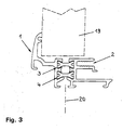
- the receiving side walls 7, 12 and the receiving side walls 8, 13 on the frame part profiles 1, 2 in the direction of in Fig. 2 shown arrows rolling force. Under the action of this force, the receiving side walls 7, 12; 8, 13 inwards in the position according to Fig. 3 bent. In the transverse direction of the profile, this results in a substantially play-free connection between the frame part profiles 1, 2 and the Distanzstegprofilen 3, 4 and thus also between the first frame part profile 1 and the second frame part profile 2.
- a corresponding design of the receiving side walls 7, 12; 8, 13 exerted compressive force in profile longitudinal direction is still a relative mobility of the frame part profiles 1, 2 on the one hand and the Distanzstegprofile 3, 4 on the other.
- the frame part profiles 1, 2 and the Distanzstegprofile 3, 4 thus relative to each other align.
- a slight frictional engagement between the frame part profiles 1, 2 and the spacer bar profiles 3, 4 is to be overcome.
- Such alignment is possible in particular automatically when the frame part profiles 1, 2 and the spacer bar profiles 3, 4 are bent together in a further manufacturing step to the desired frame.
- Due to the relative longitudinal mobility of the frame part profiles 1, 2 and the spacer bar profiles 3, 4 results in a distortion-free, inherently stable frame. In installation position, this frame holds a cutout in a Fig. 3 Dashboard shown side wall 19 of a motorhome.
- dash-dotted lines indicated a frame main plane 20 of the finished frame.
- the finished frame is powder coated under heat.
Landscapes
- Engineering & Computer Science (AREA)
- Civil Engineering (AREA)
- Structural Engineering (AREA)
- Wing Frames And Configurations (AREA)
- Body Structure For Vehicles (AREA)
- Automobile Manufacture Line, Endless Track Vehicle, Trailer (AREA)
- Power-Operated Mechanisms For Wings (AREA)
Description
- Die Erfindung betrifft ein Verfahren zum Herstellen eines Rahmens für ein Fenster, eine Tür, eine Klappe oder dergleichen, insbesondere an einem Wohnwagen oder einem Reisemobil, mit zwei in Rahmenumfangsrichtung verlaufenden und parallel zu der Rahmenhauptebene voneinander getrennten Rahmenteilen sowie mit wenigstens einem sich zwischen den Rahmenteilen in Rahmenumfangsrichtung erstreckenden Distanzsteg aus wärmedämmendem Material, - wobei wenigstens ein geradliniges Distanzstegprofil aus plastisch verformbarem Material in Distanzstegaufnahmen an zwei geradlinigen Rahmenteilprofilen aus plastisch verformbarem Material eingeführt wird,
- wobei an den Distanzstegaufnahmen zwischen dem Distanzsteg-profil und beiden der Rahmenteilprofile eine jeweils in Profilquerrichtung wirksame Verbindung hergestellt wird und
- wobei anschließend die Rahmenteilprofile sowie das Distanzstegprofil gemeinschaftlich in eine Rahmenform gebogen werden.
- Ein Verfahren der eingangs genannten Art ist in
EP 1 108 848 A1 offenbart. Im Laufe dieses Verfahrens werden zwei geradlinige Rahmenteilprofile aus Aluminium über zwei geradlinige Distanzstegprofile aus Polyamid miteinander verbunden. Hierzu werden die Distanzstegprofile mit ihren Längsrändern in Längsnuten an den einander gegenüberliegenden Rahmenteilprofilen eingeführt. - Zwischen den Rahmenteilprofilen und den Distanzstegprofilen wird eine Verbindung hergestellt, die sowohl in Längs- als auch in Querrichtung der Profile wirksam ist. Anschließend wird die Baueinheit aus den geradlinigen Rahmenteilprofilen sowie den geradlinigen Distanzstegprofilen zu einem geschlossenen Rahmen gebogen. Die aneinander stoßenden Enden der gebogenen Profile werden schließlich miteinander verbunden.
- Nachteiligerweise treten an Rahmen, die nach dem aus
EP 1 108 848 A1 bekannten Verfahren gefertigt werden, häufig unerwünschte Deformationen auf. - Ein gattungsfremdes Verfahren ist bekannt
CA 1 098 767 A . Im Rahmen des vorbekannten Herstellungsverfahrens werden zwei Rahmenteilprofile über ein schlauchartiges Isolierelement aneinander abgestützt. Zu diesem Zweck wird das schlauchartige Isolierelement in im Querschnitt bogenförmige Vertiefungen an den Rahmenteilprofilen eingeschoben. Im eingeschobenen Zustand liegt das schlauchartige Isolierelement lose in beiden bogenförmigen Vertiefungen. Es besteht folglich keine in Profilquerrichtung wirksame Verbindung zwischen dem schlauchartigen Isolierelement einerseits und den Rahmenteilprofilen andererseits. - Insoweit Abhilfe zu schaffen, hat sich die vorliegende Erfindung zum Ziel gesetzt.
- Erfindungsgemäß gelöst wird diese Aufgabe durch das Verfahren nach Patentanspruch 1. Im Falle der Erfindung wird demnach vor dem Biegen der Rahmenform zwischen dem oder den Distanzstegprofilen und den Rahmenteilprofilen eine Verbindung hergestellt, die in Profilquerrichtung wirksam ist, die aber dessen ungeachtet in Profillängsrichtung eine Relativbewegung des oder der Distanzstegprofile einerseits sowie wenigstens eines Rahmenteilprofiles andererseits zulässt. Diese relative Längsbeweglichkeit bewirkt, dass sich als Ergebnis des anschließenden Biegeprozesses eine Rahmenform ohne unerwünschte Deformationen ergibt. Bei dem Biegevorgang können sich das oder die Rahmenteilprofile und das oder die Distanzstegprofile relativ zueinander selbsttätig mit ihrem Sollverlauf in Rahmenumfangsrichtung ausrichten.
- Besondere Varianten des Verfahrens nach Patentanspruch 1 ergeben sich aus den abhängigen Patentansprüchen 2 bis 6.
- In bevorzugter Ausgestaltung der Erfindung wird ausweislich Patentanspruch 2 zwischen wenigstens einem Distanzstegprofil und beiden Rahmenteilprofilen eine in Profilquerrichtung wirksame Verbindung hergestellt, die eine relative Längsbeweglichkeit des oder der Distanzstegprofile einerseits und der Rahmenteilprofile andererseits zulässt. Diese Verfahrensvariante zeichnet sich durch ein qualitativ besonders hochwertiges Fertigungsergebnis aus.
- Ausweislich Patentanspruch 3 wird die in Profilquerrichtung wirksame und eine relative Längsbeweglichkeit in Profillängsrichtung gestattende Verbindung zwischen dem oder den Distanzstegprofilen einerseits und den Rahmenteilprofilen andererseits durch Verformung wenigstens einer der Seitenwände hergestellt, die an den Rahmenteilprofilen die Distanzsteg-Aufnahme(n) begrenzen.
- Gemäß Patentanspruch 4 werden dabei die Aufnahmeseitenwände im Interesse einer funktionssicheren und wirksamen Bauteilverbindung durch rollende Kraftbeaufschlagung verformt.
- Im Falle der Verfahrensvariante nach Patentanspruch 5 schließt sich an das gemeinschaftliche Verformen von Distanzsteg- und Rahmenteilprofilen eine Behandlung wenigstens eines der gebogenen Rahmenteile unter Hitzeeinwirkung an. In Frage kommt beispielsweise ein Pulverbeschichten des oder der Rahmenteile. Von besonderer Bedeutung ist in diesem Zusammenhang die Hitzebeständigkeit des oder der Distanzstegprofile.
- Profilwerkstoffe, mit denen sich das erfindungsgemäße Verfahren durchführen lässt, sind beispielhaft in Patentanspruch 6 genannt. Distanzstegprofile aus Polyamid besitzen insbesondere die zuvor angesprochene Hitzebeständigkeit. Als Alternativen denkbar sind beispielsweise auch Distanzstegprofile aus Polyester oder aus Epoxidharz.
- Anhand schematischer Darstellungen wird das erfindungsgemäße Verfahren nachstehend erläutert. Es zeigen:
- Fig. 1
- zwei Rahmenteilprofile sowie zwei Distanzstegprofile jeweils im Querschnitt,
- Fig. 2
- die vorläufig miteinander verbundenen Rahmenteil- und Distanzstegprofile nach
Fig. 1 und - Fig. 3
- die endgültig miteinander verbundenen Rahmenteil- und Distanzstegprofile nach den
Fign. 1 und 2 . - Ausweislich
Fig. 1 ist aus einem ersten Rahmenteilprofil 1 und einem zweiten Rahmenteilprofil 2 sowie aus einem ersten Distanzstegprofil 3 und einem zweiten Distanzstegprofil 4 ein Rahmen für ein Fenster eines Reisemobils zu fertigen. Bei den Rahmenteilprofilen 1, 2 handelt es sich um stranggepresste geradlinige Profilstäbe aus Aluminium. Die Distanzstegprofile 3, 4 sind nach einem Extrusionsverfahren aus Polyamid hergestellt worden. - Das erste Rahmenteilprofil 1 besitzt Distanzstegaufnahmen 5, 6, die von senkrecht zu der Zeichenebene von
Fig. 1 verlaufenden Aufnahmeseitenwänden 7, 8, 9 begrenzt werden. Entsprechend weist das zweite Rahmenteilprofil 2 Distanzstegaufnahmen 10, 11 mit Aufnahmeseitenwänden 12, 13, 14 auf. - Das erste Distanzstegprofil 3 ist mit Randverdickungen 15, 16, das zweite Distanzstegprofil 4 mit Randverdickungen 17, 18 versehen.
- Ursprünglich liegen die Rahmenteilprofile 1, 2 sowie die Distanzstegprofile 3, 4 jeweils als Profilstäbe mit beispielsweise 6 m Länge vor.
- Die Rahmenteilprofile 1, 2 und die Distanzstegprofile 3, 4 werden zu der in
Fig. 2 dargestellten Baueinheit vorläufig miteinander verbunden. Zu diesem Zweck wird das erste Distanzstegprofil 3 in Profillängsrichtung in die Distanzstegaufnahme 5 an dem ersten Rahmenteilprofil 1 sowie in die Distanzstegaufnahme 10 an dem zweiten Rahmenteilprofil 2 eingeführt. In entsprechender Weise wird das zweite Distanzstegprofil 4 in die Distanzstegaufnahme 6 an dem ersten Rahmenteilprofil 1 sowie in die Distanzstegaufnahme 11 an dem zweiten Rahmenteilprofil 2 eingeschoben. Es ergeben sich dann die inFig. 2 gezeigten Verhältnisse. Das erste Distanzstegprofil 3 liegt mit seinen Randverdickungen 15, 16 in den Distanzstegaufnahmen 5, 10 an den Rahmenteilprofilen 1, 2. Die Randverdickungen 17, 18 an dem zweiten Distanzstegprofil 4 befinden sich im Innern der Distanzstegaufnahmen 6, 11. Die Rahmenteilprofile 1, 2 einerseits und die Distanzstegprofile 3, 4 andererseits werden dabei mit verhältnismäßig großem Spiel in Profilquerrichtung aneinander gehalten. - Ausgehend von der in
Fig. 2 veranschaulichten Herstellungsphase werden die Aufnahmeseitenwände 7, 12 sowie die Aufnahmeseitenwände 8, 13 an den Rahmenteilprofilen 1, 2 in Richtung der inFig. 2 dargestellten Pfeile rollend kraftbeaufschlagt. Unter der Wirkung dieser Kraft werden die Aufnahmeseitenwände 7, 12; 8, 13 einwärts in die Stellung gemäßFig. 3 gebogen. In Profilquerrichtung ergibt sich dadurch eine im Wesentlichen spielfreie Verbindung zwischen den Rahmenteilprofilen 1, 2 und den Distanzstegprofilen 3, 4 und somit auch zwischen dem ersten Rahmenteilprofil 1 und dem zweiten Rahmenteilprofil 2. Infolge einer entsprechenden Bemessung der auf die Aufnahmeseitenwände 7, 12; 8, 13 ausgeübten Druckkraft besteht in Profillängsrichtung nach wie vor eine Relativbeweglichkeit der Rahmenteilprofile 1, 2 einerseits und der Distanzstegprofile 3, 4 andererseits. In Profillängsrichtung lassen sich die Rahmenteilprofile 1, 2 sowie die Distanzstegprofile 3, 4 folglich relativ zueinander ausrichten. Im gezeigten Beispielsfall ist dabei ein geringfügiger Reibschluss zwischen den Rahmenteilprofilen 1, 2 und den Distanzstegprofilen 3, 4 zu überwinden. Ein derartiges Ausrichten ist insbesondere dann selbsttätig möglich, wenn die Rahmenteilprofile 1, 2 sowie die Distanzstegprofile 3, 4 in einem weiteren Fertigungsschritt gemeinschaftlich zu dem gewünschten Rahmen gebogen werden. Unter Umständen ist vor dem Biegevorgang von der aus den Rahmenteilprofilen 1, 2 und den Distanzstegprofilen 3, 4 bestehenden geradlinigen Baueinheit ein dem Umfang des zu fertigenden Rahmens entsprechender Abschnitt abzulängen. Aufgrund der relativen Längsbeweglichkeit der Rahmenteilprofile 1, 2 sowie der Distanzstegprofile 3, 4 ergibt sich ein verzugsfreier, in sich stabiler Rahmen. In Einbaulage fasst dieser Rahmen einen Ausschnitt in einer inFig. 3 gestrichelt dargestellten Seitenwand 19 eines Reisemobils ein. InFig. 3 strichpunktiert angedeutet ist eine Rahmenhauptebene 20 des fertigen Rahmens. - Abweichend von dem vorstehend beschriebenen Ablauf ist es auch möglich, die Aufnahmeseitenwände 7, 12; 8, 13 an den Rahmenteilprofilen 1, 2 bereits vor dem Einführen der Distanzstegprofile 3, 4 aus ihren Stellungen gemäß
Fig. 2 in die Stellungen gemäßFig. 3 zu biegen. Die Distanzstegprofile 3, 4 sind in diesem Fall mit geringem Kraftaufwand in die Distanzstegaufnahmen 5, 10; 6, 11 einzuschieben. - In jedem Fall wird der fertige Rahmen unter Hitzeeinwirkung pulverbeschichtet.
- Im Interesse einer rationellen Fertigung werden die einzelnen Arbeitsschritte entlang einer Fertigungsstraße an unmittelbar aufeinander folgenden Arbeitsstationen durchgeführt.
Claims (6)
- Verfahren zum Herstellen eines Rahmens für ein Fenster, eine Tür, eine Klappe oder dergleichen, insbesondere an einem Wohnwagen oder einem Reisemobil, mit zwei in Rahmenumfangsrichtung verlaufenden und parallel zu der Rahmenhauptebene (20) voneinander getrennten Rahmenteilen sowie mit wenigstens einem sich zwischen den Rahmenteilen in Rahmenumfangsrichtung erstreckenden Distanzsteg aus wärmedämmendem Material,- wobei wenigstens ein geradliniges Distanzstegprofil (3, 4) aus plastisch verformbarem Material in Distanzstegaufnahmen (5, 10; 6, 11) an zwei geradlinigen Rahmenteilprofilen (1, 2) aus plastisch verformbarem Material eingeführt wird,- wobei an den Distanzstegaufnahmen (5, 10; 6, 11) zwischen dem Distanzstegprofil (3, 4) und beiden der Rahmenteilprofile (1, 2) eine jeweils in Profilquerrichtung wirksame Verbindung hergestellt wird und- wobei anschließend die Rahmenteilprofile (1, 2) sowie das Distanzstegprofil (3, 4) gemeinschaftlich in eine Rahmenform gebogen werden.dadurch gekennzeichnet, dass
an den Distanzstegaufnahmen (5, 10; 6, 11) zwischen dem Distanzstegprofil (3, 4) und jedem der Rahmenteilprofile (1, 2) jeweils eine Verbindung derart hergestellt wird, dass während des Biegevorganges eine relative Längsbeweglichkeit des Distanzstegprofils (3, 4) einerseits und wenigstens eines der Rahmenteilprofile (1, 2) andererseits besteht und dass das Distanzstegprofil (3, 4) und die Rahmenteilprofile (1, 2) gleichzeitig in Profilquerrichtung wirksam miteinander verbunden sind. - Verfahren nach Anspruch 1, dadurch gekennzeichnet, dass wenigstens ein Distanzstegprofil (3, 4) und die Rahmenteilprofile (1, 2) mit relativer Längsbeweglichkeit des Distanzstegprofils (3, 4) einerseits und beider Rahmenteilprofile (1, 2) andererseits und in Profilquerrichtung wirksam miteinander verbunden werden.
- Verfahren nach einem der vorhergehenden Ansprüche, dadurch gekennzeichnet, dass wenigstens ein Distanzstegprofil (3, 4) an zumindest einem Rahmenteilprofil (1, 2) in eine Distanzstegaufnahme (5, 10; 6, 11) mit in Profillängsrichtung verlaufenden Aufnahmeseitenwänden (7, 8, 9; 12, 13, 14) eingeführt und das Distanzstegprofil (3, 4) sowie das Rahmenteilprofil (1, 2) unter Verformen wenigstens einer der Aufnahmeseitenwände (7, 8, 9; 12, 13, 14) mit relativer Längsbeweglichkeit und in Profilquerrichtung wirksam miteinander verbunden werden.
- Verfahren nach einem der vorhergehenden Ansprüche, dadurch gekennzeichnet, dass wenigstens eine der Aufnahmeseitenwände (7, 8, 9; 12, 13, 14) durch rollende Kraftbeaufschlagung verformt und dadurch wenigstens ein Distanzstegprofil (3, 4) sowie zumindest ein Rahmenteilprofil (1, 2) mit relativer Längsbeweglichkeit und in Profilquerrichtung wirksam miteinander verbunden werden.
- Verfahren nach einem der vorhergehenden Ansprüche, dadurch gekennzeichnet, dass wenigstens ein Distanzstegprofil (3, 4) aus hitzebeständigem Material verwendet wird und dass wenigstens ein Rahmenteil nach dem gemeinschaftlichen Biegen des betreffenden Rahmenteilprofils (1, 2) und des betreffenden Distanzstegprofils (3, 4) unter Hitzeeinwirkung behandelt, insbesondere beschichtet wird.
- Verfahren nach einem der vorhergehenden Ansprüche, dadurch gekennzeichnet, dass wenigstens ein Rahmenteilprofil (1, 2) aus Aluminium.und/oder wenigstens ein Distanzstegprofil (3, 4) aus wärmedämmendem Kunststoff, insbesondere aus Polyamid, verwendet wird.
Applications Claiming Priority (2)
| Application Number | Priority Date | Filing Date | Title |
|---|---|---|---|
| DE10335276A DE10335276A1 (de) | 2003-08-01 | 2003-08-01 | Verfahren zum Herstellen eines Rahmens insbesondere für ein Fenster oder eine Tür an einem Wohnwagen oder einem Reisemobil |
| DE10335276 | 2003-08-01 |
Publications (3)
| Publication Number | Publication Date |
|---|---|
| EP1503023A2 EP1503023A2 (de) | 2005-02-02 |
| EP1503023A3 EP1503023A3 (de) | 2006-01-18 |
| EP1503023B1 true EP1503023B1 (de) | 2010-03-03 |
Family
ID=33521526
Family Applications (1)
| Application Number | Title | Priority Date | Filing Date |
|---|---|---|---|
| EP04017176A Expired - Lifetime EP1503023B1 (de) | 2003-08-01 | 2004-07-21 | Verfahren zum Herstellen eines Rahmens insbesondere für ein Fenster oder eine Tür an einem Wohnwagen oder einem Reisemobil |
Country Status (5)
| Country | Link |
|---|---|
| EP (1) | EP1503023B1 (de) |
| AT (1) | ATE459777T1 (de) |
| DE (2) | DE10335276A1 (de) |
| DK (1) | DK1503023T3 (de) |
| ES (1) | ES2342165T3 (de) |
Families Citing this family (3)
| Publication number | Priority date | Publication date | Assignee | Title |
|---|---|---|---|---|
| USD969694S1 (en) | 2019-08-21 | 2022-11-15 | Dometic Sweden Ab | Window |
| DE102019212527A1 (de) | 2019-08-21 | 2021-02-25 | Dometic Sweden Ab | Fenster, freizeitfahrzeug mit dem fenster und verfahren zur herstellung und betätigung des fensters |
| DE102019212529A1 (de) | 2019-08-21 | 2021-02-25 | Dometic Sweden Ab | Vorrichtung zum Haltern eines Rahmens in einer Öffnung, ein Rahmen mit einer solchen Vorrichtung, ein Fenster, ein Freizeitfahrzeug mit einem solchen Rahmen oder Fenster und Verfahren zum Haltern des Rahmens oder des Fensters in der Öffnung |
Family Cites Families (9)
| Publication number | Priority date | Publication date | Assignee | Title |
|---|---|---|---|---|
| CA1098767A (en) * | 1979-10-05 | 1981-04-07 | Jack Zintel | Multiple glazing assembly |
| DE8223301U1 (de) * | 1982-08-18 | 1982-12-30 | Michel, Hans, 7108 Möckmühl | Mehrteiliger profilrahmen, insbesondere fuer fenster und tueren |
| DE3315069C2 (de) * | 1983-04-26 | 1987-04-09 | eurAl Firmengruppe für Fenster- und Türensysteme GmbH, 3167 Burgdorf | Verbundprofil, insbesondere für Fenster und Türen, Verfahren zur Herstellung des Verbundprofiles sowie Werkzeug zur Durchführung des Verfahrens |
| DE3334332A1 (de) * | 1983-09-22 | 1985-04-04 | Julius & August Erbslöh GmbH & Co, 5600 Wuppertal | Verfahren und hohlkoerper zur herstellung einer gleitfuehrung zwischen zwei relativ zueinander beweglichen bauteilen |
| DE3501233A1 (de) * | 1985-01-16 | 1986-07-17 | IsKoAl Firmengruppe für Fenster- und Türsysteme GmbH, 3167 Burgdorf | Verfahren zur herstellung eines mehrteiligen profilrahmens |
| DE4203483A1 (de) * | 1992-02-07 | 1993-08-12 | Bernhard Kreye | Profil aus metall fuer den kreis- oder ovalfoermigen rahmen, insbesondere fluegelrahmen eines rundfensters |
| DE19637858A1 (de) * | 1996-09-17 | 1998-04-02 | Schueco Int Kg | Wärmegedämmtes Verbundprofil für Türen, Fenster oder Fassaden |
| NL1013879C2 (nl) * | 1999-12-17 | 2000-10-03 | Gemert Repair B V Van | Werkwijze voor het vervaardigen van een omlijsting voor een raam met afgeronde hoeken, alsmede omlijsting vervaardigd volgens de werkwijze. |
| NL1014407C2 (nl) * | 2000-02-17 | 2001-09-07 | David Wilhelm Zoetmulder | Raamconstructie en raamprofiel met onderbroken koudebrug. |
-
2003
- 2003-08-01 DE DE10335276A patent/DE10335276A1/de not_active Withdrawn
-
2004
- 2004-07-21 DK DK04017176.1T patent/DK1503023T3/da active
- 2004-07-21 DE DE502004010836T patent/DE502004010836D1/de not_active Expired - Lifetime
- 2004-07-21 AT AT04017176T patent/ATE459777T1/de not_active IP Right Cessation
- 2004-07-21 ES ES04017176T patent/ES2342165T3/es not_active Expired - Lifetime
- 2004-07-21 EP EP04017176A patent/EP1503023B1/de not_active Expired - Lifetime
Also Published As
| Publication number | Publication date |
|---|---|
| EP1503023A2 (de) | 2005-02-02 |
| DE10335276A1 (de) | 2005-03-03 |
| DK1503023T3 (da) | 2010-05-10 |
| EP1503023A3 (de) | 2006-01-18 |
| DE502004010836D1 (de) | 2010-04-15 |
| ATE459777T1 (de) | 2010-03-15 |
| ES2342165T3 (es) | 2010-07-02 |
Similar Documents
| Publication | Publication Date | Title |
|---|---|---|
| EP2942466B1 (de) | Verbundprofil mit Lastabtragungseinrichtungen für Befestigungsmittel eines Funktionselementes, insbesondere ein Bandelement und Verfahren zur Montage eines solchen Funktionselementes | |
| EP2385181A2 (de) | Brandschutzelement | |
| DE3006056A1 (de) | Torblatt fuer ein deckenglieder- oder rolltor | |
| EP0716210A2 (de) | Eckverbinder zum Verbinden von Kunststoffprofilen | |
| EP1503023B1 (de) | Verfahren zum Herstellen eines Rahmens insbesondere für ein Fenster oder eine Tür an einem Wohnwagen oder einem Reisemobil | |
| DE19857589C2 (de) | Aufprallträger für Fahrzeugtüren und Verfahren zu seiner Herstellung | |
| DE102018131967A1 (de) | Verfahren zum Kalibrieren eines gekrümmten metallischen Hohlkammerprofils | |
| EP2977119B1 (de) | Verfahren zum herstellen eines torsionsprofils aus einer platine sowie torsionsprofil | |
| DE102005046843B3 (de) | Vorrichtung und Verfahren zur Herstellung eines einbaufertigen Zusammenbauteils | |
| EP1154115A1 (de) | Ausschäumbares Hohlprofil | |
| EP2108757A1 (de) | Montagewinkel für Fassadenelemente und Verfahren zu dessen Herstellung | |
| DE102007057724A1 (de) | Tragkonstruktion und ein Verfahren zu deren Herstellung | |
| EP3423659B1 (de) | Verbundprofil für eine tür, ein fenster oder ein fassadenelement sowie verfahren zur herstellung des verbundprofils | |
| DE102008054159A1 (de) | Verfahren zum Herstellen einer Klemmleiste | |
| EP2030825B1 (de) | Verfahren zum Herstellen einer Klemmleiste | |
| EP2316712B1 (de) | Verbundprofil bestehend aus wenigstens einem ersten und zweiten Metallprofilteil | |
| EP3048232B1 (de) | Metallprofil, Verbundprofil mit einem solchen Metallprofil sowie Verfahren zur Herstellung des Metallprofils | |
| DE102012014790A1 (de) | Montageschiene sowie Verfahren zu deren Herstellung | |
| EP2959985B1 (de) | Profilträger mit einer erhöhten biegefestigkeit aus kaltband sowie verfahren zur herstellung eines solchen | |
| DE19611687A1 (de) | Adapterprofil zur Verbindung von Rahmenprofilen | |
| EP2366489B1 (de) | Vorrichtung zum Einpressen von Isolierstegen | |
| EP1215360A1 (de) | Verbundprofil | |
| DE102005049542B3 (de) | Verfahren zum Herstellen eines Profils durch Walzprofilieren und eines Strukturbauteils | |
| DE102005020751B3 (de) | Verfahren zur Herstellung eines Bandlappens und Bandlappen | |
| DE102006040519A1 (de) | Verfahren zur Herstellung einer Stromschiene |
Legal Events
| Date | Code | Title | Description |
|---|---|---|---|
| PUAI | Public reference made under article 153(3) epc to a published international application that has entered the european phase |
Free format text: ORIGINAL CODE: 0009012 |
|
| AK | Designated contracting states |
Kind code of ref document: A2 Designated state(s): AT BE BG CH CY CZ DE DK EE ES FI FR GB GR HU IE IT LI LU MC NL PL PT RO SE SI SK TR |
|
| AX | Request for extension of the european patent |
Extension state: AL HR LT LV MK |
|
| PUAL | Search report despatched |
Free format text: ORIGINAL CODE: 0009013 |
|
| AK | Designated contracting states |
Kind code of ref document: A3 Designated state(s): AT BE BG CH CY CZ DE DK EE ES FI FR GB GR HU IE IT LI LU MC NL PL PT RO SE SI SK TR |
|
| AX | Request for extension of the european patent |
Extension state: AL HR LT LV MK |
|
| RAP1 | Party data changed (applicant data changed or rights of an application transferred) |
Owner name: DOMETIC SEITZ GMBH |
|
| 17P | Request for examination filed |
Effective date: 20060308 |
|
| AKX | Designation fees paid |
Designated state(s): AT BE BG CH CY CZ DE DK EE ES FI FR GB GR HU IE IT LI LU MC NL PL PT RO SE SI SK TR |
|
| 17Q | First examination report despatched |
Effective date: 20080110 |
|
| GRAP | Despatch of communication of intention to grant a patent |
Free format text: ORIGINAL CODE: EPIDOSNIGR1 |
|
| GRAS | Grant fee paid |
Free format text: ORIGINAL CODE: EPIDOSNIGR3 |
|
| GRAA | (expected) grant |
Free format text: ORIGINAL CODE: 0009210 |
|
| AK | Designated contracting states |
Kind code of ref document: B1 Designated state(s): AT BE BG CH CY CZ DE DK EE ES FI FR GB GR HU IE IT LI LU MC NL PL PT RO SE SI SK TR |
|
| REG | Reference to a national code |
Ref country code: GB Ref legal event code: FG4D Free format text: NOT ENGLISH |
|
| REG | Reference to a national code |
Ref country code: CH Ref legal event code: EP |
|
| REG | Reference to a national code |
Ref country code: IE Ref legal event code: FG4D |
|
| REF | Corresponds to: |
Ref document number: 502004010836 Country of ref document: DE Date of ref document: 20100415 Kind code of ref document: P |
|
| REG | Reference to a national code |
Ref country code: DK Ref legal event code: T3 |
|
| REG | Reference to a national code |
Ref country code: SE Ref legal event code: TRGR |
|
| REG | Reference to a national code |
Ref country code: NL Ref legal event code: T3 |
|
| REG | Reference to a national code |
Ref country code: ES Ref legal event code: FG2A Ref document number: 2342165 Country of ref document: ES Kind code of ref document: T3 |
|
| PG25 | Lapsed in a contracting state [announced via postgrant information from national office to epo] |
Ref country code: PL Free format text: LAPSE BECAUSE OF FAILURE TO SUBMIT A TRANSLATION OF THE DESCRIPTION OR TO PAY THE FEE WITHIN THE PRESCRIBED TIME-LIMIT Effective date: 20100303 Ref country code: SI Free format text: LAPSE BECAUSE OF FAILURE TO SUBMIT A TRANSLATION OF THE DESCRIPTION OR TO PAY THE FEE WITHIN THE PRESCRIBED TIME-LIMIT Effective date: 20100303 |
|
| REG | Reference to a national code |
Ref country code: IE Ref legal event code: FD4D |
|
| PG25 | Lapsed in a contracting state [announced via postgrant information from national office to epo] |
Ref country code: GR Free format text: LAPSE BECAUSE OF FAILURE TO SUBMIT A TRANSLATION OF THE DESCRIPTION OR TO PAY THE FEE WITHIN THE PRESCRIBED TIME-LIMIT Effective date: 20100604 Ref country code: RO Free format text: LAPSE BECAUSE OF FAILURE TO SUBMIT A TRANSLATION OF THE DESCRIPTION OR TO PAY THE FEE WITHIN THE PRESCRIBED TIME-LIMIT Effective date: 20100303 Ref country code: CY Free format text: LAPSE BECAUSE OF FAILURE TO SUBMIT A TRANSLATION OF THE DESCRIPTION OR TO PAY THE FEE WITHIN THE PRESCRIBED TIME-LIMIT Effective date: 20100303 Ref country code: EE Free format text: LAPSE BECAUSE OF FAILURE TO SUBMIT A TRANSLATION OF THE DESCRIPTION OR TO PAY THE FEE WITHIN THE PRESCRIBED TIME-LIMIT Effective date: 20100303 Ref country code: IE Free format text: LAPSE BECAUSE OF FAILURE TO SUBMIT A TRANSLATION OF THE DESCRIPTION OR TO PAY THE FEE WITHIN THE PRESCRIBED TIME-LIMIT Effective date: 20100303 |
|
| PGFP | Annual fee paid to national office [announced via postgrant information from national office to epo] |
Ref country code: ES Payment date: 20100830 Year of fee payment: 7 Ref country code: NL Payment date: 20100726 Year of fee payment: 7 |
|
| PG25 | Lapsed in a contracting state [announced via postgrant information from national office to epo] |
Ref country code: SK Free format text: LAPSE BECAUSE OF FAILURE TO SUBMIT A TRANSLATION OF THE DESCRIPTION OR TO PAY THE FEE WITHIN THE PRESCRIBED TIME-LIMIT Effective date: 20100303 Ref country code: CZ Free format text: LAPSE BECAUSE OF FAILURE TO SUBMIT A TRANSLATION OF THE DESCRIPTION OR TO PAY THE FEE WITHIN THE PRESCRIBED TIME-LIMIT Effective date: 20100303 Ref country code: BG Free format text: LAPSE BECAUSE OF FAILURE TO SUBMIT A TRANSLATION OF THE DESCRIPTION OR TO PAY THE FEE WITHIN THE PRESCRIBED TIME-LIMIT Effective date: 20100603 |
|
| PGFP | Annual fee paid to national office [announced via postgrant information from national office to epo] |
Ref country code: AT Payment date: 20100721 Year of fee payment: 7 Ref country code: DE Payment date: 20100723 Year of fee payment: 7 Ref country code: FI Payment date: 20100721 Year of fee payment: 7 Ref country code: FR Payment date: 20100802 Year of fee payment: 7 Ref country code: IT Payment date: 20100728 Year of fee payment: 7 Ref country code: LU Payment date: 20100723 Year of fee payment: 7 Ref country code: SE Payment date: 20100723 Year of fee payment: 7 |
|
| PGFP | Annual fee paid to national office [announced via postgrant information from national office to epo] |
Ref country code: GB Payment date: 20100726 Year of fee payment: 7 |
|
| PLBE | No opposition filed within time limit |
Free format text: ORIGINAL CODE: 0009261 |
|
| STAA | Information on the status of an ep patent application or granted ep patent |
Free format text: STATUS: NO OPPOSITION FILED WITHIN TIME LIMIT |
|
| PG25 | Lapsed in a contracting state [announced via postgrant information from national office to epo] |
Ref country code: PT Free format text: LAPSE BECAUSE OF FAILURE TO SUBMIT A TRANSLATION OF THE DESCRIPTION OR TO PAY THE FEE WITHIN THE PRESCRIBED TIME-LIMIT Effective date: 20100705 |
|
| PGFP | Annual fee paid to national office [announced via postgrant information from national office to epo] |
Ref country code: DK Payment date: 20100726 Year of fee payment: 7 |
|
| 26N | No opposition filed |
Effective date: 20101206 |
|
| PG25 | Lapsed in a contracting state [announced via postgrant information from national office to epo] |
Ref country code: MC Free format text: LAPSE BECAUSE OF NON-PAYMENT OF DUE FEES Effective date: 20100731 |
|
| PGFP | Annual fee paid to national office [announced via postgrant information from national office to epo] |
Ref country code: BE Payment date: 20100727 Year of fee payment: 7 |
|
| REG | Reference to a national code |
Ref country code: CH Ref legal event code: PL |
|
| PG25 | Lapsed in a contracting state [announced via postgrant information from national office to epo] |
Ref country code: CH Free format text: LAPSE BECAUSE OF NON-PAYMENT OF DUE FEES Effective date: 20100731 Ref country code: LI Free format text: LAPSE BECAUSE OF NON-PAYMENT OF DUE FEES Effective date: 20100731 |
|
| BERE | Be: lapsed |
Owner name: DOMETIC SEITZ G.M.B.H. Effective date: 20110731 |
|
| REG | Reference to a national code |
Ref country code: NL Ref legal event code: V1 Effective date: 20120201 |
|
| REG | Reference to a national code |
Ref country code: SE Ref legal event code: EUG |
|
| REG | Reference to a national code |
Ref country code: DK Ref legal event code: EBP |
|
| GBPC | Gb: european patent ceased through non-payment of renewal fee |
Effective date: 20110721 |
|
| REG | Reference to a national code |
Ref country code: AT Ref legal event code: MM01 Ref document number: 459777 Country of ref document: AT Kind code of ref document: T Effective date: 20110721 |
|
| REG | Reference to a national code |
Ref country code: FR Ref legal event code: ST Effective date: 20120330 |
|
| PG25 | Lapsed in a contracting state [announced via postgrant information from national office to epo] |
Ref country code: FR Free format text: LAPSE BECAUSE OF NON-PAYMENT OF DUE FEES Effective date: 20110801 Ref country code: BE Free format text: LAPSE BECAUSE OF NON-PAYMENT OF DUE FEES Effective date: 20110731 Ref country code: DE Free format text: LAPSE BECAUSE OF NON-PAYMENT OF DUE FEES Effective date: 20120201 |
|
| REG | Reference to a national code |
Ref country code: DE Ref legal event code: R119 Ref document number: 502004010836 Country of ref document: DE Effective date: 20120201 |
|
| PG25 | Lapsed in a contracting state [announced via postgrant information from national office to epo] |
Ref country code: NL Free format text: LAPSE BECAUSE OF NON-PAYMENT OF DUE FEES Effective date: 20120201 Ref country code: IT Free format text: LAPSE BECAUSE OF NON-PAYMENT OF DUE FEES Effective date: 20110721 Ref country code: FI Free format text: LAPSE BECAUSE OF NON-PAYMENT OF DUE FEES Effective date: 20110721 |
|
| PG25 | Lapsed in a contracting state [announced via postgrant information from national office to epo] |
Ref country code: GB Free format text: LAPSE BECAUSE OF NON-PAYMENT OF DUE FEES Effective date: 20110721 |
|
| PG25 | Lapsed in a contracting state [announced via postgrant information from national office to epo] |
Ref country code: DK Free format text: LAPSE BECAUSE OF NON-PAYMENT OF DUE FEES Effective date: 20110731 |
|
| PG25 | Lapsed in a contracting state [announced via postgrant information from national office to epo] |
Ref country code: HU Free format text: LAPSE BECAUSE OF FAILURE TO SUBMIT A TRANSLATION OF THE DESCRIPTION OR TO PAY THE FEE WITHIN THE PRESCRIBED TIME-LIMIT Effective date: 20100904 |
|
| PG25 | Lapsed in a contracting state [announced via postgrant information from national office to epo] |
Ref country code: TR Free format text: LAPSE BECAUSE OF FAILURE TO SUBMIT A TRANSLATION OF THE DESCRIPTION OR TO PAY THE FEE WITHIN THE PRESCRIBED TIME-LIMIT Effective date: 20100303 |
|
| REG | Reference to a national code |
Ref country code: ES Ref legal event code: FD2A Effective date: 20121122 |
|
| PG25 | Lapsed in a contracting state [announced via postgrant information from national office to epo] |
Ref country code: AT Free format text: LAPSE BECAUSE OF NON-PAYMENT OF DUE FEES Effective date: 20110721 |
|
| PG25 | Lapsed in a contracting state [announced via postgrant information from national office to epo] |
Ref country code: ES Free format text: LAPSE BECAUSE OF NON-PAYMENT OF DUE FEES Effective date: 20110722 |
|
| PG25 | Lapsed in a contracting state [announced via postgrant information from national office to epo] |
Ref country code: SE Free format text: LAPSE BECAUSE OF NON-PAYMENT OF DUE FEES Effective date: 20110722 |
|
| PG25 | Lapsed in a contracting state [announced via postgrant information from national office to epo] |
Ref country code: LU Free format text: LAPSE BECAUSE OF NON-PAYMENT OF DUE FEES Effective date: 20110721 |