EP2366625A2 - Moteur d'aéronef doté d'un échangeur thermique à huile optimisé - Google Patents
Moteur d'aéronef doté d'un échangeur thermique à huile optimisé Download PDFInfo
- Publication number
- EP2366625A2 EP2366625A2 EP11001798A EP11001798A EP2366625A2 EP 2366625 A2 EP2366625 A2 EP 2366625A2 EP 11001798 A EP11001798 A EP 11001798A EP 11001798 A EP11001798 A EP 11001798A EP 2366625 A2 EP2366625 A2 EP 2366625A2
- Authority
- EP
- European Patent Office
- Prior art keywords
- nozzle tube
- ejector nozzle
- flow
- oil cooler
- aircraft engine
- Prior art date
- Legal status (The legal status is an assumption and is not a legal conclusion. Google has not performed a legal analysis and makes no representation as to the accuracy of the status listed.)
- Granted
Links
- 239000012080 ambient air Substances 0.000 claims 1
- 238000010276 construction Methods 0.000 description 5
- 238000005452 bending Methods 0.000 description 4
- 238000005457 optimization Methods 0.000 description 3
- 239000002184 metal Substances 0.000 description 2
- 239000002245 particle Substances 0.000 description 2
- 238000011144 upstream manufacturing Methods 0.000 description 2
- 230000001133 acceleration Effects 0.000 description 1
- 230000003321 amplification Effects 0.000 description 1
- 238000013459 approach Methods 0.000 description 1
- 238000001816 cooling Methods 0.000 description 1
- 230000000694 effects Effects 0.000 description 1
- 238000005516 engineering process Methods 0.000 description 1
- 239000012530 fluid Substances 0.000 description 1
- 238000003801 milling Methods 0.000 description 1
- 238000003199 nucleic acid amplification method Methods 0.000 description 1
- 239000000725 suspension Substances 0.000 description 1
- 238000003466 welding Methods 0.000 description 1
Images

Classifications
-
- B—PERFORMING OPERATIONS; TRANSPORTING
- B64—AIRCRAFT; AVIATION; COSMONAUTICS
- B64D—EQUIPMENT FOR FITTING IN OR TO AIRCRAFT; FLIGHT SUITS; PARACHUTES; ARRANGEMENT OR MOUNTING OF POWER PLANTS OR PROPULSION TRANSMISSIONS IN AIRCRAFT
- B64D27/00—Arrangement or mounting of power plants in aircraft; Aircraft characterised by the type or position of power plants
- B64D27/02—Aircraft characterised by the type or position of power plants
- B64D27/10—Aircraft characterised by the type or position of power plants of gas-turbine type
- B64D27/14—Aircraft characterised by the type or position of power plants of gas-turbine type within, or attached to, fuselages
-
- B—PERFORMING OPERATIONS; TRANSPORTING
- B64—AIRCRAFT; AVIATION; COSMONAUTICS
- B64D—EQUIPMENT FOR FITTING IN OR TO AIRCRAFT; FLIGHT SUITS; PARACHUTES; ARRANGEMENT OR MOUNTING OF POWER PLANTS OR PROPULSION TRANSMISSIONS IN AIRCRAFT
- B64D29/00—Power-plant nacelles, fairings or cowlings
- B64D29/04—Power-plant nacelles, fairings or cowlings associated with fuselages
-
- B—PERFORMING OPERATIONS; TRANSPORTING
- B64—AIRCRAFT; AVIATION; COSMONAUTICS
- B64D—EQUIPMENT FOR FITTING IN OR TO AIRCRAFT; FLIGHT SUITS; PARACHUTES; ARRANGEMENT OR MOUNTING OF POWER PLANTS OR PROPULSION TRANSMISSIONS IN AIRCRAFT
- B64D33/00—Arrangement in aircraft of power plant parts or auxiliaries not otherwise provided for
- B64D33/08—Arrangement in aircraft of power plant parts or auxiliaries not otherwise provided for of power plant cooling systems
- B64D33/10—Radiator arrangement
-
- B—PERFORMING OPERATIONS; TRANSPORTING
- B64—AIRCRAFT; AVIATION; COSMONAUTICS
- B64D—EQUIPMENT FOR FITTING IN OR TO AIRCRAFT; FLIGHT SUITS; PARACHUTES; ARRANGEMENT OR MOUNTING OF POWER PLANTS OR PROPULSION TRANSMISSIONS IN AIRCRAFT
- B64D27/00—Arrangement or mounting of power plants in aircraft; Aircraft characterised by the type or position of power plants
- B64D2027/005—Aircraft with an unducted turbofan comprising contra-rotating rotors, e.g. contra-rotating open rotors [CROR]
-
- B—PERFORMING OPERATIONS; TRANSPORTING
- B64—AIRCRAFT; AVIATION; COSMONAUTICS
- B64D—EQUIPMENT FOR FITTING IN OR TO AIRCRAFT; FLIGHT SUITS; PARACHUTES; ARRANGEMENT OR MOUNTING OF POWER PLANTS OR PROPULSION TRANSMISSIONS IN AIRCRAFT
- B64D27/00—Arrangement or mounting of power plants in aircraft; Aircraft characterised by the type or position of power plants
- B64D27/02—Aircraft characterised by the type or position of power plants
- B64D27/026—Aircraft characterised by the type or position of power plants comprising different types of power plants, e.g. combination of a piston engine and a gas-turbine
-
- Y—GENERAL TAGGING OF NEW TECHNOLOGICAL DEVELOPMENTS; GENERAL TAGGING OF CROSS-SECTIONAL TECHNOLOGIES SPANNING OVER SEVERAL SECTIONS OF THE IPC; TECHNICAL SUBJECTS COVERED BY FORMER USPC CROSS-REFERENCE ART COLLECTIONS [XRACs] AND DIGESTS
- Y02—TECHNOLOGIES OR APPLICATIONS FOR MITIGATION OR ADAPTATION AGAINST CLIMATE CHANGE
- Y02T—CLIMATE CHANGE MITIGATION TECHNOLOGIES RELATED TO TRANSPORTATION
- Y02T50/00—Aeronautics or air transport
- Y02T50/60—Efficient propulsion technologies, e.g. for aircraft
Definitions
- the invention relates to an aircraft engine with optimized oil heat exchanger and to an ejector nozzle tube to be used therefor.
- the invention has for its object to provide an aircraft engine with optimized oil heat exchanger and an ejector nozzle tube, which avoid the disadvantages of the prior art with a simple structure and simple, cost-effective applicability and ensure effective heat transfer at low noise level.
- the aircraft engine has at least one oil cooler heat radiator / heat exchanger, which is arranged in a trailing edge region of a wing-like structure.
- This may be a pylon for suspension of the engine or a part of the wing construction.
- At least one flow introduction region is provided in order to supply air from the ambient flow to the oil cooler, which is arranged in a flow channel.
- an ejector nozzle tube according to the invention Downstream of the oil cooler, an ejector nozzle tube according to the invention is arranged, which is designed such that an optimized flow results in the region of the ejector nozzle tube.
- This flow produces a considerably reduced noise potential in comparison with the prior art and thus leads on the one hand to an optimization of the flow through the oil cooler / heat exchanger and, on the other hand, to a drastic minimization of noise.
- the ejector nozzle tube according to the invention has over its length substantially constant, substantially an oval or S-shaped form having cross section, which is hollow, to introduce an additional air flow through the ejector nozzle tube.
- the ejector nozzle tube according to the invention at its flow leading edge region on a flow bar, which is provided with a rounded or curved cross-section.
- the Anströmmann is provided with a plurality of grooves which open to the top and bottom of the ejector nozzle tube cross-section. The central region of the grooves is connected to the interior of the ejector nozzle tube, so that the air supply is ensured by the grooves.
- the inflow strip can be produced in a simple manner as a milled component and welded to the remaining sheet-like structure (bending structure) of the ejector nozzle tube. This results in a particularly cost manufacturability.
- the mode of operation of the ejector nozzle tube according to the invention is based on the arrangement of the ejector nozzles at the leading edge. This results in a flow along the surface of the ejector-nozzle tube, which significantly increases the operation, compared with the known from the prior art constructions. In the known from the prior art ejector nozzle tubes, it is known to provide the nozzles at the trailing edge (trailing edge).
- the fluid particles which are supplied from the oil cooler / heat exchanger, the ejector nozzle tube, accelerated by the friction with the emerging from the nozzles of the Anströmang fluting.
- the velocity difference between the respective particles creates a friction and transfers kinetic energy from the flow exiting the nozzles of the ejector nozzle tube to the flow exiting the oil cooler. As a result, the entire flow is accelerated.
- the flow channel can be adapted with regard to its geometry.
- at least one adjustable wall element is provided.
- an upper and a lower adjustable wall element are provided, which are designed in the form of a pivoting flap. This makes it possible to change the cross section of the flow channel and, due to the structuring, to further influence the flow conditions, in particular by forming an additional nozzle through the two pivoting flaps.
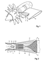
- the Fig. 1 shows a gas turbine engine with two counter-rotating pressure propellers. Such constructions are known from the prior art, so that a detailed description can be dispensed with at this point.
- the gas turbine engine is supported on a wing-like structure 8, such as a pylon or wing.
- the Fig. 2 shows the outflow of the structure 8. This has upper and lower Strömungseinleit Schemee 9, which are each formed slit-like. As a result, part of the flow 13 flowing through the structure 8 is deflected and fed to a flow channel 10. In the flow channel 10, an oil cooler / heat exchanger 6 is arranged, which is flowed through by the flow.
- an ejector nozzle tube 1 is arranged in the flow channel 10, which subsequently in conjunction with the Fig. 3 to 5 will be described in detail.
- an upper pivot flap 11 and a lower pivot flap 12 are arranged, which are each pivotable about a substantially horizontal axis.
- the Fig. 3 shows an enlarged view analog Fig. 2 .
- the ejector nozzle tube 1 has a flow-optimized, substantially oval, over its length constant cross-section and is provided with an interior through which an additional air flow can be supplied.
- a flow bar 2 is attached on the upstream side of the ejector nozzle tube. This is provided with a thicker cross section and formed for example as a milled part. The remaining wall region of the ejector nozzle tube 1 is designed as a bent sheet metal part (see also 4 and 5 ).
- the region of the flow channel 10, in which the ejector nozzle tube 1 is arranged, is contoured by the upper pivot flap 11 and the lower pivot flap 12, so that there is an exhaust nozzle 15, which generates additional thrust.
- the air supplied to the ejector nozzle tube 1 is usually bleed air of the gas turbine engine of the aircraft gas turbine engine.
- Fig. 3 is the clear cross section between the pivoting flaps 11 and 12, in Fig. 3 is shown as a double arrow A, equal to or less than the maximum total thickness of the oval or S-shaped cross section of the ejector nozzle tube 1. In Fig. 3 this thickness is represented by the double arrow B.
- a ⁇ B the average thickness of the oval or S-shaped cross section of the ejector nozzle tube 1.
- the arrow 17 in Fig. 3 shows the exit of the ejector flow at the upstream region of the ejector nozzle tube.
- the 4 and 5 show clarifying the design, in particular the Anströmmann 2.
- This has arc-shaped grooves 3, which have a substantially constant cross-section and extend in accordance with the arcuate shape of the Anströmmann.
- the flow supplied in the interior 5 of the ejector nozzle tube 1 can be guided and discharged through the nozzles 4.
- the ejector nozzle tube may be connected to the sheet bending structure of the main part of the ejector nozzle tube 1 via welding points 18.
- An essential aspect of the present invention is the simple and cost-effective manufacturability of the ejector nozzle tube 1. This can be formed as a simple, inexpensive sheet-metal bending part, wherein the cross-sectional shape can be realized easily and inexpensively.
- the Anströmmann 2 is also produced as a simple, inexpensive milled part, which can be connected to the sheet-bending construction of the actual body of the ejector nozzle tube in a simple manner, for example by welded joints. Due to the milling construction of the inflow strip, the grooves can be produced easily and inexpensively, as can the outlet openings for the flow emerging from the ejector nozzle tube.
Landscapes
- Engineering & Computer Science (AREA)
- Aviation & Aerospace Engineering (AREA)
- Mechanical Engineering (AREA)
- Chemical & Material Sciences (AREA)
- Combustion & Propulsion (AREA)
- Jet Pumps And Other Pumps (AREA)
- Heat-Exchange Devices With Radiators And Conduit Assemblies (AREA)
- Details Of Heat-Exchange And Heat-Transfer (AREA)
Applications Claiming Priority (1)
| Application Number | Priority Date | Filing Date | Title |
|---|---|---|---|
| DE102010010128A DE102010010128A1 (de) | 2010-03-04 | 2010-03-04 | Flugzeugtriebwerk mit optimiertem Ölwärmetauscher |
Publications (3)
| Publication Number | Publication Date |
|---|---|
| EP2366625A2 true EP2366625A2 (fr) | 2011-09-21 |
| EP2366625A3 EP2366625A3 (fr) | 2013-12-25 |
| EP2366625B1 EP2366625B1 (fr) | 2015-05-20 |
Family
ID=44063861
Family Applications (1)
| Application Number | Title | Priority Date | Filing Date |
|---|---|---|---|
| EP20110001798 Not-in-force EP2366625B1 (fr) | 2010-03-04 | 2011-03-03 | Moteur d'aéronef doté d'un échangeur thermique à huile optimisé |
Country Status (3)
| Country | Link |
|---|---|
| US (1) | US8690098B2 (fr) |
| EP (1) | EP2366625B1 (fr) |
| DE (1) | DE102010010128A1 (fr) |
Cited By (1)
| Publication number | Priority date | Publication date | Assignee | Title |
|---|---|---|---|---|
| FR3044292A1 (fr) * | 2015-11-26 | 2017-06-02 | Airbus Operations Sas | Profil aerodynamique d'aeronef a bord d'attaque ouvert, mat et aeronef comportant un tel profil aerodynamique |
Families Citing this family (20)
| Publication number | Priority date | Publication date | Assignee | Title |
|---|---|---|---|---|
| US9260191B2 (en) * | 2011-08-26 | 2016-02-16 | Hs Marston Aerospace Ltd. | Heat exhanger apparatus including heat transfer surfaces |
| FR3022588B1 (fr) * | 2014-06-24 | 2016-06-24 | Snecma | Dispositif de refroidissement pour une turbomachine |
| FR3032942B1 (fr) * | 2015-02-19 | 2018-11-23 | Safran Aircraft Engines | Ensemble propulsif pour aeronef comprenant un turboreacteur a soufflante non carenee et un pylone d'accrochage |
| USD868627S1 (en) | 2018-04-27 | 2019-12-03 | Jetoptera, Inc. | Flying car |
| US10464668B2 (en) | 2015-09-02 | 2019-11-05 | Jetoptera, Inc. | Configuration for vertical take-off and landing system for aerial vehicles |
| US20200324891A1 (en) * | 2015-09-02 | 2020-10-15 | Jetoptera, Inc. | Adaptive vertical take-off and landing propulsion system |
| EP4306789A3 (fr) | 2015-09-02 | 2024-06-12 | Jetoptera, Inc. | Système propulsif fluidique |
| US10106246B2 (en) | 2016-06-10 | 2018-10-23 | Coflow Jet, LLC | Fluid systems that include a co-flow jet |
| US10315754B2 (en) | 2016-06-10 | 2019-06-11 | Coflow Jet, LLC | Fluid systems that include a co-flow jet |
| US11168951B2 (en) | 2016-07-14 | 2021-11-09 | General Electric Company | Entrainment heat exchanger |
| US10683076B2 (en) | 2017-10-31 | 2020-06-16 | Coflow Jet, LLC | Fluid systems that include a co-flow jet |
| US11293293B2 (en) | 2018-01-22 | 2022-04-05 | Coflow Jet, LLC | Turbomachines that include a casing treatment |
| US11111025B2 (en) | 2018-06-22 | 2021-09-07 | Coflow Jet, LLC | Fluid systems that prevent the formation of ice |
| PL426033A1 (pl) | 2018-06-22 | 2020-01-02 | General Electric Company | Płynowe pompy strumieniowe parowe, a także układy i sposoby porywania płynu przy użyciu płynowych pomp strumieniowych parowych |
| CN109229339A (zh) * | 2018-08-30 | 2019-01-18 | 哈尔滨飞机工业集团有限责任公司 | 一种直升机动力舱前部整流罩 |
| US11920617B2 (en) | 2019-07-23 | 2024-03-05 | Coflow Jet, LLC | Fluid systems and methods that address flow separation |
| WO2021257271A1 (fr) | 2020-06-17 | 2021-12-23 | Coflow Jet, LLC | Systèmes fluidiques ayant une configuration variable |
| US11512639B2 (en) | 2021-01-26 | 2022-11-29 | General Electric Company | Heat transfer system |
| WO2022204278A1 (fr) | 2021-03-26 | 2022-09-29 | Coflow Jet, LLC | Pales d'éolienne et systèmes d'éolienne comprenant un jet à écoulement descendant |
| US20240308677A1 (en) * | 2023-03-17 | 2024-09-19 | Pratt & Whitney Canada Corp. | Heat exchanger assembly for an aircraft |
Family Cites Families (20)
| Publication number | Priority date | Publication date | Assignee | Title |
|---|---|---|---|---|
| US1412073A (en) * | 1920-06-28 | 1922-04-11 | Hugo Junkers | Arrangement of radiators in flying machines |
| US1730978A (en) * | 1928-06-09 | 1929-10-08 | Lepere Eugene Marie Georges | Arrangement for mounting radiators in aeroplane wings |
| US2117632A (en) * | 1937-01-26 | 1938-05-17 | United Aircraft Corp | Wing radiator |
| US2352144A (en) * | 1940-08-22 | 1944-06-20 | Bell Aircraft Corp | Wing slot closure member |
| US4763842A (en) * | 1987-02-04 | 1988-08-16 | Bill D. McCarthy | Water drip device for irrigation |
| US4782658A (en) * | 1987-05-07 | 1988-11-08 | Rolls-Royce Plc | Deicing of a geared gas turbine engine |
| ZA873956B (en) * | 1987-06-03 | 1988-01-27 | Gilead Gideon | Irrigation device |
| US5520339A (en) * | 1994-12-13 | 1996-05-28 | Kuo; Ming-Shish | Multi-stage dripping tube for irrigation |
| DE19524731A1 (de) * | 1995-07-07 | 1997-01-09 | Bmw Rolls Royce Gmbh | Turboprop-Triebwerk mit einem Luft-Ölkühler |
| FR2742479B1 (fr) * | 1995-12-13 | 1998-01-16 | Snecma | Dispositif de refroidissement d'un turbomoteur sur aeronef |
| FR2788308A1 (fr) * | 1999-01-07 | 2000-07-13 | Snecma | Dispositif de refroidissement d'un reducteur de vitesse de turbomachine |
| US6651929B2 (en) * | 2001-10-29 | 2003-11-25 | Pratt & Whitney Canada Corp. | Passive cooling system for auxiliary power unit installation |
| GB2389174B (en) * | 2002-05-01 | 2005-10-26 | Rolls Royce Plc | Cooling systems |
| WO2005061323A1 (fr) * | 2003-11-21 | 2005-07-07 | Airbus | Systeme de refroidissement d'un fluide d'un aeronef et aeronef equipe d'un tel systeme |
| FR2891248B1 (fr) * | 2005-09-28 | 2009-05-01 | Airbus France Sas | Ensemble moteur pour aeronef comprenant un moteur ainsi qu'un mat d'accrochage d'un tel moteur |
| US8408281B2 (en) * | 2007-10-15 | 2013-04-02 | Lockheed Martin Corporation | System, method, and apparatus for pulsed-jet-enhanced heat exchanger |
| DE102008028987A1 (de) | 2008-06-20 | 2009-12-24 | Rolls-Royce Deutschland Ltd & Co Kg | Turboproptriebwerk mit einer Vorrichtung zum Erzeugen eines Kühlluftstroms |
| DE102009011452A1 (de) * | 2009-03-03 | 2010-09-09 | Rolls-Royce Deutschland Ltd & Co Kg | Verfahren zur Herstellung eines Ejektor-Düsen-Rohrs |
| GB2473651B (en) * | 2009-09-21 | 2011-08-31 | Rolls Royce Plc | Gas turbine aircraft engines and operation thereof |
| DE102009055879A1 (de) * | 2009-11-26 | 2011-06-01 | Rolls-Royce Deutschland Ltd & Co Kg | Flugzeugenteisungsvorrichtung und Triebwerksgondel einer Fluggasturbine mit Enteisungsvorrichtung |
-
2010
- 2010-03-04 DE DE102010010128A patent/DE102010010128A1/de not_active Withdrawn
-
2011
- 2011-03-03 EP EP20110001798 patent/EP2366625B1/fr not_active Not-in-force
- 2011-03-03 US US13/039,795 patent/US8690098B2/en not_active Expired - Fee Related
Non-Patent Citations (1)
| Title |
|---|
| None |
Cited By (1)
| Publication number | Priority date | Publication date | Assignee | Title |
|---|---|---|---|---|
| FR3044292A1 (fr) * | 2015-11-26 | 2017-06-02 | Airbus Operations Sas | Profil aerodynamique d'aeronef a bord d'attaque ouvert, mat et aeronef comportant un tel profil aerodynamique |
Also Published As
| Publication number | Publication date |
|---|---|
| US20110215172A1 (en) | 2011-09-08 |
| US8690098B2 (en) | 2014-04-08 |
| EP2366625A3 (fr) | 2013-12-25 |
| DE102010010128A1 (de) | 2011-09-08 |
| EP2366625B1 (fr) | 2015-05-20 |
Similar Documents
| Publication | Publication Date | Title |
|---|---|---|
| EP2366625B1 (fr) | Moteur d'aéronef doté d'un échangeur thermique à huile optimisé | |
| EP2378072B1 (fr) | Canal en dérivation d'un turboréacteur | |
| EP2185412B1 (fr) | Soupape de décharge pour un aéronef | |
| EP0126399B1 (fr) | Conduit de fluide présentant une construction réduite | |
| EP2059655B1 (fr) | Aube mobile refroidie pour turbines | |
| DE102012000376B4 (de) | Axial- oder Diagonalventilator | |
| EP2226473B1 (fr) | Elément déflecteur d'air d'un système de réglage du jeu des extrémités des aubes d'une turbine à gaz d'avion | |
| EP2362065B1 (fr) | Canal de dérivation avec couronne d'aubes statoriques dans un turboréacteur avec soufflante | |
| EP2669474A1 (fr) | Canal de passage pour une turbomachine et turbomachine | |
| EP2828598B1 (fr) | Échangeur de chaleur, procédé de production correspondant et divers systèmes avec un tel échangeur de chaleur | |
| EP1292760B1 (fr) | Configuration d'une aube de turbine pouvant etre refroidie | |
| EP2455665A2 (fr) | Chambre de combustion de turbine à gaz dotée d'un dispositif d'amenée d'air de refroidissement | |
| DE102005016570A1 (de) | Reduzierung von Reibungsverlusten im Bereich von Grenzschichten an fluidumströmten Oberflächen | |
| EP0848144A1 (fr) | Tuyau de sortie pour le conduit d'échappement d'un pÔt d'échappement d'un véhicule à moteur | |
| DE112009001754T5 (de) | Abgasdiffusor für Gasturbine | |
| EP2322866B9 (fr) | Libération de torsion pour l'aération de pièces | |
| EP1766192A1 (fr) | Roue a aubes d'une turbine presentant une aube et au moins un canal refrigerant | |
| EP2489837A1 (fr) | Insert de dosage pour aube de turbine et aube de turbine associée | |
| DE102020200447A1 (de) | Gehäuse für einen Ventilator und Ventilator mit einem entsprechenden Gehäuse | |
| EP2225467B1 (fr) | Appareil de production de rotation et turbocompresseur équipé d'un tel appareil | |
| EP3232001A1 (fr) | Aube rotorique de turbine | |
| DE102020117405B4 (de) | Luftleitvorrichtung für eine Kraftfahrzeugkarosserie und Kraftfahrzeugkarosserie | |
| EP2134925B1 (fr) | Turbocompresseur à suralimentation de gaz d'échappement et son fonctionnement | |
| WO2017167456A1 (fr) | Filtre à liquide | |
| EP4296489B1 (fr) | Entrée d'air |
Legal Events
| Date | Code | Title | Description |
|---|---|---|---|
| PUAI | Public reference made under article 153(3) epc to a published international application that has entered the european phase |
Free format text: ORIGINAL CODE: 0009012 |
|
| AK | Designated contracting states |
Kind code of ref document: A2 Designated state(s): AL AT BE BG CH CY CZ DE DK EE ES FI FR GB GR HR HU IE IS IT LI LT LU LV MC MK MT NL NO PL PT RO RS SE SI SK SM TR |
|
| AX | Request for extension of the european patent |
Extension state: BA ME |
|
| PUAL | Search report despatched |
Free format text: ORIGINAL CODE: 0009013 |
|
| AK | Designated contracting states |
Kind code of ref document: A3 Designated state(s): AL AT BE BG CH CY CZ DE DK EE ES FI FR GB GR HR HU IE IS IT LI LT LU LV MC MK MT NL NO PL PT RO RS SE SI SK SM TR |
|
| AX | Request for extension of the european patent |
Extension state: BA ME |
|
| RIC1 | Information provided on ipc code assigned before grant |
Ipc: B64D 27/14 20060101AFI20131115BHEP Ipc: B64D 33/10 20060101ALI20131115BHEP |
|
| 17P | Request for examination filed |
Effective date: 20140219 |
|
| RBV | Designated contracting states (corrected) |
Designated state(s): AL AT BE BG CH CY CZ DE DK EE ES FI FR GB GR HR HU IE IS IT LI LT LU LV MC MK MT NL NO PL PT RO RS SE SI SK SM TR |
|
| GRAP | Despatch of communication of intention to grant a patent |
Free format text: ORIGINAL CODE: EPIDOSNIGR1 |
|
| INTG | Intention to grant announced |
Effective date: 20141212 |
|
| GRAS | Grant fee paid |
Free format text: ORIGINAL CODE: EPIDOSNIGR3 |
|
| GRAA | (expected) grant |
Free format text: ORIGINAL CODE: 0009210 |
|
| AK | Designated contracting states |
Kind code of ref document: B1 Designated state(s): AL AT BE BG CH CY CZ DE DK EE ES FI FR GB GR HR HU IE IS IT LI LT LU LV MC MK MT NL NO PL PT RO RS SE SI SK SM TR |
|
| REG | Reference to a national code |
Ref country code: GB Ref legal event code: FG4D Free format text: NOT ENGLISH |
|
| REG | Reference to a national code |
Ref country code: CH Ref legal event code: EP |
|
| REG | Reference to a national code |
Ref country code: AT Ref legal event code: REF Ref document number: 727615 Country of ref document: AT Kind code of ref document: T Effective date: 20150615 |
|
| REG | Reference to a national code |
Ref country code: IE Ref legal event code: FG4D Free format text: LANGUAGE OF EP DOCUMENT: GERMAN |
|
| REG | Reference to a national code |
Ref country code: DE Ref legal event code: R096 Ref document number: 502011006851 Country of ref document: DE |
|
| REG | Reference to a national code |
Ref country code: LT Ref legal event code: MG4D |
|
| REG | Reference to a national code |
Ref country code: NL Ref legal event code: MP Effective date: 20150520 |
|
| PG25 | Lapsed in a contracting state [announced via postgrant information from national office to epo] |
Ref country code: PT Free format text: LAPSE BECAUSE OF FAILURE TO SUBMIT A TRANSLATION OF THE DESCRIPTION OR TO PAY THE FEE WITHIN THE PRESCRIBED TIME-LIMIT Effective date: 20150921 Ref country code: LT Free format text: LAPSE BECAUSE OF FAILURE TO SUBMIT A TRANSLATION OF THE DESCRIPTION OR TO PAY THE FEE WITHIN THE PRESCRIBED TIME-LIMIT Effective date: 20150520 Ref country code: FI Free format text: LAPSE BECAUSE OF FAILURE TO SUBMIT A TRANSLATION OF THE DESCRIPTION OR TO PAY THE FEE WITHIN THE PRESCRIBED TIME-LIMIT Effective date: 20150520 Ref country code: HR Free format text: LAPSE BECAUSE OF FAILURE TO SUBMIT A TRANSLATION OF THE DESCRIPTION OR TO PAY THE FEE WITHIN THE PRESCRIBED TIME-LIMIT Effective date: 20150520 Ref country code: NO Free format text: LAPSE BECAUSE OF FAILURE TO SUBMIT A TRANSLATION OF THE DESCRIPTION OR TO PAY THE FEE WITHIN THE PRESCRIBED TIME-LIMIT Effective date: 20150820 Ref country code: ES Free format text: LAPSE BECAUSE OF FAILURE TO SUBMIT A TRANSLATION OF THE DESCRIPTION OR TO PAY THE FEE WITHIN THE PRESCRIBED TIME-LIMIT Effective date: 20150520 |
|
| PG25 | Lapsed in a contracting state [announced via postgrant information from national office to epo] |
Ref country code: GR Free format text: LAPSE BECAUSE OF FAILURE TO SUBMIT A TRANSLATION OF THE DESCRIPTION OR TO PAY THE FEE WITHIN THE PRESCRIBED TIME-LIMIT Effective date: 20150821 Ref country code: BG Free format text: LAPSE BECAUSE OF FAILURE TO SUBMIT A TRANSLATION OF THE DESCRIPTION OR TO PAY THE FEE WITHIN THE PRESCRIBED TIME-LIMIT Effective date: 20150820 Ref country code: RS Free format text: LAPSE BECAUSE OF FAILURE TO SUBMIT A TRANSLATION OF THE DESCRIPTION OR TO PAY THE FEE WITHIN THE PRESCRIBED TIME-LIMIT Effective date: 20150520 Ref country code: LV Free format text: LAPSE BECAUSE OF FAILURE TO SUBMIT A TRANSLATION OF THE DESCRIPTION OR TO PAY THE FEE WITHIN THE PRESCRIBED TIME-LIMIT Effective date: 20150520 Ref country code: IS Free format text: LAPSE BECAUSE OF FAILURE TO SUBMIT A TRANSLATION OF THE DESCRIPTION OR TO PAY THE FEE WITHIN THE PRESCRIBED TIME-LIMIT Effective date: 20150920 |
|
| PG25 | Lapsed in a contracting state [announced via postgrant information from national office to epo] |
Ref country code: EE Free format text: LAPSE BECAUSE OF FAILURE TO SUBMIT A TRANSLATION OF THE DESCRIPTION OR TO PAY THE FEE WITHIN THE PRESCRIBED TIME-LIMIT Effective date: 20150520 Ref country code: DK Free format text: LAPSE BECAUSE OF FAILURE TO SUBMIT A TRANSLATION OF THE DESCRIPTION OR TO PAY THE FEE WITHIN THE PRESCRIBED TIME-LIMIT Effective date: 20150520 |
|
| REG | Reference to a national code |
Ref country code: DE Ref legal event code: R097 Ref document number: 502011006851 Country of ref document: DE |
|
| PG25 | Lapsed in a contracting state [announced via postgrant information from national office to epo] |
Ref country code: SK Free format text: LAPSE BECAUSE OF FAILURE TO SUBMIT A TRANSLATION OF THE DESCRIPTION OR TO PAY THE FEE WITHIN THE PRESCRIBED TIME-LIMIT Effective date: 20150520 Ref country code: PL Free format text: LAPSE BECAUSE OF FAILURE TO SUBMIT A TRANSLATION OF THE DESCRIPTION OR TO PAY THE FEE WITHIN THE PRESCRIBED TIME-LIMIT Effective date: 20150520 Ref country code: RO Free format text: LAPSE BECAUSE OF NON-PAYMENT OF DUE FEES Effective date: 20150520 Ref country code: CZ Free format text: LAPSE BECAUSE OF FAILURE TO SUBMIT A TRANSLATION OF THE DESCRIPTION OR TO PAY THE FEE WITHIN THE PRESCRIBED TIME-LIMIT Effective date: 20150520 |
|
| PLBE | No opposition filed within time limit |
Free format text: ORIGINAL CODE: 0009261 |
|
| STAA | Information on the status of an ep patent application or granted ep patent |
Free format text: STATUS: NO OPPOSITION FILED WITHIN TIME LIMIT |
|
| REG | Reference to a national code |
Ref country code: FR Ref legal event code: PLFP Year of fee payment: 6 |
|
| 26N | No opposition filed |
Effective date: 20160223 |
|
| PG25 | Lapsed in a contracting state [announced via postgrant information from national office to epo] |
Ref country code: IT Free format text: LAPSE BECAUSE OF FAILURE TO SUBMIT A TRANSLATION OF THE DESCRIPTION OR TO PAY THE FEE WITHIN THE PRESCRIBED TIME-LIMIT Effective date: 20150520 |
|
| PG25 | Lapsed in a contracting state [announced via postgrant information from national office to epo] |
Ref country code: SI Free format text: LAPSE BECAUSE OF FAILURE TO SUBMIT A TRANSLATION OF THE DESCRIPTION OR TO PAY THE FEE WITHIN THE PRESCRIBED TIME-LIMIT Effective date: 20150520 |
|
| PG25 | Lapsed in a contracting state [announced via postgrant information from national office to epo] |
Ref country code: BE Free format text: LAPSE BECAUSE OF NON-PAYMENT OF DUE FEES Effective date: 20160331 |
|
| PG25 | Lapsed in a contracting state [announced via postgrant information from national office to epo] |
Ref country code: MC Free format text: LAPSE BECAUSE OF FAILURE TO SUBMIT A TRANSLATION OF THE DESCRIPTION OR TO PAY THE FEE WITHIN THE PRESCRIBED TIME-LIMIT Effective date: 20150520 Ref country code: LU Free format text: LAPSE BECAUSE OF FAILURE TO SUBMIT A TRANSLATION OF THE DESCRIPTION OR TO PAY THE FEE WITHIN THE PRESCRIBED TIME-LIMIT Effective date: 20160303 |
|
| REG | Reference to a national code |
Ref country code: CH Ref legal event code: PL |
|
| REG | Reference to a national code |
Ref country code: IE Ref legal event code: MM4A |
|
| PG25 | Lapsed in a contracting state [announced via postgrant information from national office to epo] |
Ref country code: LI Free format text: LAPSE BECAUSE OF NON-PAYMENT OF DUE FEES Effective date: 20160331 Ref country code: IE Free format text: LAPSE BECAUSE OF NON-PAYMENT OF DUE FEES Effective date: 20160303 Ref country code: CH Free format text: LAPSE BECAUSE OF NON-PAYMENT OF DUE FEES Effective date: 20160331 |
|
| REG | Reference to a national code |
Ref country code: FR Ref legal event code: PLFP Year of fee payment: 7 |
|
| REG | Reference to a national code |
Ref country code: AT Ref legal event code: MM01 Ref document number: 727615 Country of ref document: AT Kind code of ref document: T Effective date: 20160303 |
|
| PG25 | Lapsed in a contracting state [announced via postgrant information from national office to epo] |
Ref country code: NL Free format text: LAPSE BECAUSE OF FAILURE TO SUBMIT A TRANSLATION OF THE DESCRIPTION OR TO PAY THE FEE WITHIN THE PRESCRIBED TIME-LIMIT Effective date: 20150520 Ref country code: SE Free format text: LAPSE BECAUSE OF FAILURE TO SUBMIT A TRANSLATION OF THE DESCRIPTION OR TO PAY THE FEE WITHIN THE PRESCRIBED TIME-LIMIT Effective date: 20150520 |
|
| PG25 | Lapsed in a contracting state [announced via postgrant information from national office to epo] |
Ref country code: AT Free format text: LAPSE BECAUSE OF NON-PAYMENT OF DUE FEES Effective date: 20160303 Ref country code: MT Free format text: LAPSE BECAUSE OF FAILURE TO SUBMIT A TRANSLATION OF THE DESCRIPTION OR TO PAY THE FEE WITHIN THE PRESCRIBED TIME-LIMIT Effective date: 20150520 |
|
| REG | Reference to a national code |
Ref country code: FR Ref legal event code: PLFP Year of fee payment: 8 |
|
| PG25 | Lapsed in a contracting state [announced via postgrant information from national office to epo] |
Ref country code: CY Free format text: LAPSE BECAUSE OF FAILURE TO SUBMIT A TRANSLATION OF THE DESCRIPTION OR TO PAY THE FEE WITHIN THE PRESCRIBED TIME-LIMIT Effective date: 20150520 Ref country code: SM Free format text: LAPSE BECAUSE OF FAILURE TO SUBMIT A TRANSLATION OF THE DESCRIPTION OR TO PAY THE FEE WITHIN THE PRESCRIBED TIME-LIMIT Effective date: 20150520 Ref country code: HU Free format text: LAPSE BECAUSE OF FAILURE TO SUBMIT A TRANSLATION OF THE DESCRIPTION OR TO PAY THE FEE WITHIN THE PRESCRIBED TIME-LIMIT; INVALID AB INITIO Effective date: 20110303 |
|
| PG25 | Lapsed in a contracting state [announced via postgrant information from national office to epo] |
Ref country code: TR Free format text: LAPSE BECAUSE OF FAILURE TO SUBMIT A TRANSLATION OF THE DESCRIPTION OR TO PAY THE FEE WITHIN THE PRESCRIBED TIME-LIMIT Effective date: 20150520 Ref country code: MK Free format text: LAPSE BECAUSE OF FAILURE TO SUBMIT A TRANSLATION OF THE DESCRIPTION OR TO PAY THE FEE WITHIN THE PRESCRIBED TIME-LIMIT Effective date: 20150520 |
|
| PG25 | Lapsed in a contracting state [announced via postgrant information from national office to epo] |
Ref country code: AL Free format text: LAPSE BECAUSE OF FAILURE TO SUBMIT A TRANSLATION OF THE DESCRIPTION OR TO PAY THE FEE WITHIN THE PRESCRIBED TIME-LIMIT Effective date: 20150520 |
|
| PGFP | Annual fee paid to national office [announced via postgrant information from national office to epo] |
Ref country code: DE Payment date: 20200327 Year of fee payment: 10 Ref country code: GB Payment date: 20200327 Year of fee payment: 10 |
|
| PGFP | Annual fee paid to national office [announced via postgrant information from national office to epo] |
Ref country code: FR Payment date: 20200325 Year of fee payment: 10 |
|
| REG | Reference to a national code |
Ref country code: DE Ref legal event code: R082 Ref document number: 502011006851 Country of ref document: DE |
|
| REG | Reference to a national code |
Ref country code: DE Ref legal event code: R119 Ref document number: 502011006851 Country of ref document: DE |
|
| GBPC | Gb: european patent ceased through non-payment of renewal fee |
Effective date: 20210303 |
|
| PG25 | Lapsed in a contracting state [announced via postgrant information from national office to epo] |
Ref country code: DE Free format text: LAPSE BECAUSE OF NON-PAYMENT OF DUE FEES Effective date: 20211001 Ref country code: GB Free format text: LAPSE BECAUSE OF NON-PAYMENT OF DUE FEES Effective date: 20210303 Ref country code: FR Free format text: LAPSE BECAUSE OF NON-PAYMENT OF DUE FEES Effective date: 20210331 |