EP2367013B1 - Analyseur d'échantillon - Google Patents
Analyseur d'échantillon Download PDFInfo
- Publication number
- EP2367013B1 EP2367013B1 EP11158794.5A EP11158794A EP2367013B1 EP 2367013 B1 EP2367013 B1 EP 2367013B1 EP 11158794 A EP11158794 A EP 11158794A EP 2367013 B1 EP2367013 B1 EP 2367013B1
- Authority
- EP
- European Patent Office
- Prior art keywords
- reagent
- antenna
- reagent container
- electric wave
- tag
- Prior art date
- Legal status (The legal status is an assumption and is not a legal conclusion. Google has not performed a legal analysis and makes no representation as to the accuracy of the status listed.)
- Active
Links
Images









Classifications
-
- G—PHYSICS
- G01—MEASURING; TESTING
- G01N—INVESTIGATING OR ANALYSING MATERIALS BY DETERMINING THEIR CHEMICAL OR PHYSICAL PROPERTIES
- G01N35/00—Automatic analysis not limited to methods or materials provided for in any single one of groups G01N1/00 - G01N33/00; Handling materials therefor
- G01N35/02—Automatic analysis not limited to methods or materials provided for in any single one of groups G01N1/00 - G01N33/00; Handling materials therefor using a plurality of sample containers moved by a conveyor system past one or more treatment or analysis stations
- G01N35/04—Details of the conveyor system
-
- G—PHYSICS
- G01—MEASURING; TESTING
- G01N—INVESTIGATING OR ANALYSING MATERIALS BY DETERMINING THEIR CHEMICAL OR PHYSICAL PROPERTIES
- G01N35/00—Automatic analysis not limited to methods or materials provided for in any single one of groups G01N1/00 - G01N33/00; Handling materials therefor
- G01N35/00584—Control arrangements for automatic analysers
- G01N35/00722—Communications; Identification
- G01N35/00732—Identification of carriers, materials or components in automatic analysers
-
- G—PHYSICS
- G01—MEASURING; TESTING
- G01N—INVESTIGATING OR ANALYSING MATERIALS BY DETERMINING THEIR CHEMICAL OR PHYSICAL PROPERTIES
- G01N35/00—Automatic analysis not limited to methods or materials provided for in any single one of groups G01N1/00 - G01N33/00; Handling materials therefor
- G01N35/00584—Control arrangements for automatic analysers
- G01N35/00722—Communications; Identification
- G01N35/00732—Identification of carriers, materials or components in automatic analysers
- G01N2035/00742—Type of codes
-
- G—PHYSICS
- G01—MEASURING; TESTING
- G01N—INVESTIGATING OR ANALYSING MATERIALS BY DETERMINING THEIR CHEMICAL OR PHYSICAL PROPERTIES
- G01N35/00—Automatic analysis not limited to methods or materials provided for in any single one of groups G01N1/00 - G01N33/00; Handling materials therefor
- G01N35/00584—Control arrangements for automatic analysers
- G01N35/00722—Communications; Identification
- G01N35/00732—Identification of carriers, materials or components in automatic analysers
- G01N2035/00742—Type of codes
- G01N2035/00782—Type of codes reprogrammmable code
-
- G—PHYSICS
- G01—MEASURING; TESTING
- G01N—INVESTIGATING OR ANALYSING MATERIALS BY DETERMINING THEIR CHEMICAL OR PHYSICAL PROPERTIES
- G01N35/00—Automatic analysis not limited to methods or materials provided for in any single one of groups G01N1/00 - G01N33/00; Handling materials therefor
- G01N35/02—Automatic analysis not limited to methods or materials provided for in any single one of groups G01N1/00 - G01N33/00; Handling materials therefor using a plurality of sample containers moved by a conveyor system past one or more treatment or analysis stations
- G01N35/04—Details of the conveyor system
- G01N2035/0439—Rotary sample carriers, i.e. carousels
- G01N2035/0443—Rotary sample carriers, i.e. carousels for reagents
Definitions
- the present invention relates to a sample analyzer, and in particular, to a sample analyzer for mounting a reagent container with an electronic tag recorded with reagent information.
- a sample analyzer for mounting a reagent container with an electronic tag recorded with reagent information is conventionally known.
- Japanese Patent Publication No. 2009-210444 discloses an automatic analyzer including: a circular ring-shaped reagent container holding unit for holding a plurality of reagent containers with a wireless IC tag recorded with reagent information in two rows of an inner peripheral row and an outer peripheral row; an inner peripheral antenna for emitting an electric wave to the wireless IC tag of the reagent container held at the reagent container holding unit of the inner peripheral row; an outer peripheral antenna for emitting an electric wave to the wireless IC tag of the reagent container held at the reagent container holding unit of the outer peripheral row; and an information reading and recording portion for receiving the electric wave returned from the wireless IC from the inner peripheral antenna and the outer peripheral antenna.
- the inner peripheral antenna is arranged on the inner side of the reagent container holding unit of the inner peripheral row
- the outer peripheral antenna is arranged on the outer side of the reagent container holding unit of the outer peripheral row.
- US 5,500,651 A discloses a system and method for communicating between an identification reader and a transponder unit.
- a first interrogation signal of first read range is transmitted from the reader.
- a first response signal is then received at the reader after which a second interrogation signal is transmitted from the reader.
- the second interrogation signal has a second read range which is different from the first read range.
- the read range can be varied by varying either the amplitude or duration of the power level of the interrogation signal.
- a second response signal is then received at the reader. These consecutive responses are then compared determine a correct response signal which can be displayed.
- a first aspect is a sample analyzer for analyzing a sample using a reagent in a reagent container comprising: a first reagent container holding unit configured to hold a first reagent container attached with a first electronic tag recorded with reagent information regarding a reagent; a second reagent container holding unit configured to hold a second reagent container attached with a second electronic tag recorded with reagent information regarding a reagent, and being arranged on one side of the first reagent container holding unit; a reagent information reading unit comprising an electric wave emitting portion and configured to read the reagent information recorded in the first electronic tag and the reagent information recorded in the second electronic tag; and a control unit for the reagent information reading unit, wherein the electric wave emitting portion is arranged on a side other than the one side of the first reagent container holding unit and is configured to emit a plurality of electric waves having mutually differing reaching ranges, and wherein the control unit controls the reagent information reading unit to switch the electric wave
- a region on one side of a first reagent container holding unit needs to be ensured to arrange an electric wave emitting portion, and the region on the other side of the first reagent container holding unit does not need to be ensured, and hence the device main body is suppressed from enlarging by such amount. Since the control unit can emit the electric wave of a reaching range corresponding to a reading target from the electric wave emitting portion, the reading operation of the reagent information may be more accurately carried out even if the electric wave emitting portion is arranged only on one side of the first reagent container holding unit.
- control unit controls the reagent information reading unit to cause the electric wave emitting portion to emit an electric wave of a first reaching range when the read target is the first electronic tag, and to emit an electric wave of a second reaching range greater than the first reaching range when the read target is the second electronic tag.
- the reagent information is suppressed from being mistakenly read from a plurality of first electronic tags and second electronic tags at the periphery adjacent to the first electronic tag of the reading target when reading the reagent information from the first electronic tags of the first reagent container even if the electric wave emitting portion is arranged only in the region on one side of the first reagent container holding unit.
- the electric wave emitting portion includes a shared antenna for selectively emitting the plurality of electric waves having mutually differing reaching ranges, and the control unit controls the reagent information reading unit to switch the electric wave emitted from the shared antenna in accordance with the read target being the first electronic tag or the second electronic tag.
- the electric wave emitting portion for reading the first electronic tag of the first reagent container and the electric wave emitting portion for reading the second electronic tag of the second reagent container do not need to be arranged individually, and thus the number of components can be suppressed from increasing by such amount.
- the sample analyzer further comprises a drive unit configured to move at least one of the first reagent container holding unit and the shared antenna, wherein the control unit controls the drive unit to evacuate the first reagent container from a position facing the shared antenna when the read target is the second electronic tag.
- the second electronic tag can be suppressed from being difficult to be read due to the first reagent container.
- a second aspect is a sample analyzer for analyzing a sample using a reagent in a reagent container
- a first reagent container holding unit configured to hold a first reagent container attached with a first electronic tag recorded with reagent information regarding a reagent
- a second reagent container holding unit configured to hold a second reagent container attached with a second electronic tag recorded with reagent information regarding a reagent, and being arranged on one side with respect to the first reagent container holding unit
- an antenna arranged on a side other than the one side with respect to the first reagent container holding unit and is configured to receive respective electric waves from the first electronic tag of the first reagent container and from the second electronic tag of the second reagent container
- a reagent information acquiring unit configured to acquire the reagent information recorded in the first electronic tag based on the electric wave received by the antenna from the first electronic tag, and to acquire the reagent information recorded in the second electronic tag based on the electric wave received by the antenna from the second
- the antenna does not need to be individually arranged in each of the first reagent container holding unit and the second reagent container holding unit.
- the number of components thus can be suppressed from increasing by such amount.
- only a region on one side of the first reagent container holding unit needs to be ensured to arrange the antenna , and the region on the other side of the second reagent container holding unit does not need to be ensured, and hence the device main body is suppressed from enlarging by such amount.
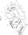
- the sample transport section 3 is configured to transport a rack mounted with a plurality of test tubes (not shown) accommodating samples.
- the sample transport section 3 is configured to transport the test tube accommodating the sample to a sample aspirating position by a sample dispensing arm 5.
- the R1 reagent dispensing arm 6 aspirates the R1 reagent installed at the reagent installing unit 16, and dispenses (discharges) the aspirated R1 reagent to the cuvette mounted at the sample discharging position.
- the R1 reagent dispensing arm 6 also transfers the cuvette mounted at the sample discharging position to the reaction unit 9 by a catcher (not shown).
- the sample dispensing arm 5 is configured to aspirate the sample in the test tube transported to the sample aspirating position by the sample transport section 3, and dispense (discharge) the sample to the cuvette at the sample discharging position dispensed with the R1 reagent by the R1 reagent dispensing arm 6.
- the R1 reagent container 22 is formed with a lid 22a that opens and closes when aspirating the R1 reagent, and a reagent accommodating portion 22b for accommodating the R1 reagent.
- the R2 reagent container 24 is formed with a lid 24a that opens and closes when aspirating the R2 reagent, and a reagent accommodating portion 24b for accommodating the R2 reagent.
- the IC tag 26 of the R2 reagent container 24 is configured so that read and write are carried out at the front surface position (facing position) of the short distance antenna 20, as shown in Fig. 6 .
- the IC tag 26 is configured to emit the response electric wave including the reagent information recorded on the IC tag 26 based on the short distance read electric wave in the range A (thick chain dashed line) emitted from the short distance antenna 20.
- the IC tag 26 is also configured to rewrite the recorded reagent information to the new reagent information contained in the short distance write electric wave based on the short distance write electric wave in the range A emitted from the short distance antenna 20.
- the interval between the adjacent R1/R3 holding members 18a and the interval between the adjacent R2 holding members 19a, the range A and the range B are set so that read and write are carried out on specific IC tags 25 and 26, and read and write are not carried out on the other IC tags 25 and 26.
- the reagent information is recorded in the IC tags 25 and 26 in an encrypted state.
- the storage unit 4d thus stores the positional information and the reagent information of twenty-five R1 reagent containers 22, the twenty-five R3 reagent containers 23, and the twenty-five R2 reagent containers 24 in a corresponded state.
- the reagent information is stored in the storage unit 4d of the control device 4 in the decrypted state.
- the IC tags IC tags 25 and 26
- the CPU 4a of the control device 4 updates the reagent information stored in the storage unit 4d to the reagent information acquired from the IC tag when the power supply is turned ON.
- the reagent information stored in the storage unit 4d of the control device 4 can be updated to the information of the reagent currently installed at the reagent installing unit 16.
- the RFID module 17 is arranged exterior to the reagent installing unit 16, and includes a reader/writer substrate 17a, an interface substrate 17b for intermediating the reader/writer substrate 17a and the CPU 2a, and an antenna switching substrate 17c, as shown in Fig. 3 .
- the reader/writer substrate 17a includes a set value storing portion 17d for storing a set value corresponding to the antenna substrate 20b, a set value corresponding to the antenna substrate 21b, and a set value of transmission output to the antenna substrate, where such set values are set by the CPU 2a.
- the antenna switching substrate 17c receives the signal corresponding to the set value stored in the set value storing portion 17d from the reader/writer substrate 17a, and switching to transmit and receive the read electric wave and the write electric wave using either the short distance antenna 20 or the long distance antenna 21 based on the received signal.
- the RFID module 17, the short distance antenna 20 and the long distance antenna 21 configure a reagent information reading unit 200 for reading the reagent information recorded on the IC tags 25 and 26.
- the short distance antenna 20 and the long distance antenna 21 respectively functions as an electric wave emitting portion 200a for emitting electric wave to the IC tags 26 and 25.
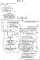
- the CPU 2a of the measurement mechanism section 2 initializes the program in step S1 and executes an initialization process such as operation check of each unit of the measurement mechanism section 2.
- step S2 the reagent information reading process is performed in step S2.
- the reagent information reading process will be described in detail later.
- step S3 whether or not a measurement instruction by the user is made is determined by the CPU 2a.
- the measurement instruction by the user is transmitted to the CPU 2a through the control device 4 (see Fig. 3 ). If determined that the measurement instruction by the user is not made, the process proceeds to step S6.
- step S3 If determined that the measurement instruction by the user is made in step S3, the reagent aspirating/reagent information writing process is carried out by the CPU 2a in step S4.
- the reagent aspirating/reagent information writing process will be described in detail later.
- step S201 whether or not the IC tag of the read target is the IC tag 25 of the R1 reagent container 22 is determined by the CPU 2a. If the IC tag of the read target is the IC tag 25 of the R1 reagent container 22, the process proceeds to step S202. If determined that the IC tag of the read target is the IC tag 26 of the R2 reagent container 24, the process proceeds to step S206.
- step S202 the antenna that emits the read electric wave is set to the long distance antenna 21 by the CPU 2a.
- the set value corresponding to the antenna substrate 21b of the long distance antenna 21 and the set value of the transmission output corresponding to the antenna substrate 21b are set in the set value storing portion 17d of the reader/writer substrate 17a by the CPU 2a.
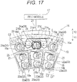
- step S203 the R1/R3 installing portion 18 is rotated in the direction of the arrow C1 or the direction of the arrow C2 (see Fig. 17 ) so that the IC tag 25 of the read target is positioned at the position opposing the long distance antenna 21 by the CPU 2a.
- step S205 the R2 installing portion 19 is rotated in the direction of the arrow D1 or the direction of the arrow D2 (see Fig. 17 ) so that the R2 reagent container 24 positioned in the region E is evacuated from the region E by the CPU 2a.
- the gap F between the adjacent R2 reagent containers 24 and the IC tag 25 of the read target are arranged at the position opposing the long distance antenna 21, and the IC tag 26 of the R2 reagent container 24 is arranged at the position not opposing the long distance antenna 21.
- step S208 If determined that none of the R2 reagent containers 24 is positioned in the region E in step S204, the process proceeds to step S208.
- the antenna that emits the read electric wave is set to the short distance antenna 20 by the CPU 2a in step S206.
- the set value corresponding to the antenna substrate 20b of the short distance antenna 20 and the set value of the transmission output corresponding to the antenna substrate 20b are set in the set value storing portion 17d of the reader/writer substrate 17a by the CPU 2a.
- step S208 the long distance read electric wave in the range B (short distance read electric wave in the range A) is emitted from the long distance antenna 21 (short distance antenna 20) to the IC tag 25 of the R1 reagent container 22 (IC tag 26 of the R2 reagent container 24) of the read target by the control of the CPU 2a, the reader/writer substrate 17a, and the antenna switching substrate 17c.
- step S209 whether or not the response electric wave emitted from the IC tag 25 or 26 in correspondence to the long distance read electric wave or the short distance read electric wave is received within a predetermined time by the long distance antenna 21 (short distance antenna 20) is determined by the CPU 2a.
- the CPU 2a determines whether or not the reagent information acquired by the reader/writer substrate 17a of the RFID module 17 based on the response electric wave received from the long distance antenna 21 (short distance antenna 20) is output to the CPU 2a within a predetermined time. If determined that the long distance antenna 21 (short distance antenna 20) did not receive the response electric wave within a predetermined time, the read error information is transmitted to the control device 4 by the CPU 2a in step S210.
- a notification that reading of the reagent information of the reagent container positioned at a predetermined position (reagent information of the reagent container of the read target) failed is displayed on the display unit 4b of the control device 4. The process then proceeds to step S213.
- step S401 whether or not the reagent container of the target (aspirating target) to aspirate the reagent is the R1 reagent container 22 or the R3 reagent container 23 is determined by the CPU 2a.
- the reagent container of the aspirating target is transmitted to the CPU 2a through the CPU 4a based on the measurement conditions and the like input to the input unit 4c by the user.
- step S404 the R1 reagent (R3 reagent) is aspirated by the R1 reagent dispensing arm 6 (R3 reagent dispensing arm 8).
- step S405 the R1/R3 installing portion 18 is rotated in the direction of the arrow C1 or the direction of the arrow C2 so that the IC tag 25 of the R1 reagent container 22 of the write target is positioned at a position opposing the long distance antenna 21 by the CPU 2a.
- the lid 22a of the R1 reagent container 22 (lid 23a of the R3 reagent container 23) is closed with the rotation of the R1/R3 installing portion 18.
- step S410 the R2 reagent is aspirated by the R2 reagent dispensing arm 7.
- step S411 the R2 installing portion 19 is rotated in the direction of the arrow D1 or the direction of the arrow D2 so that the IC tag 26 of the R2 reagent container 24 of the write target is positioned at a position opposing the short distance antenna 20 by the CPU 2a.
- the lid 24a of the R2 reagent container 24 is closed with the rotation of the R2 installing portion 19. The process then proceeds to step S412.
- step S412 the long distance read electric wave in the range B (short distance read electric wave in the range A) is emitted from the long distance antenna 21 (short distance antenna 20) to the IC tag 25 of the R1 reagent container 22 (IC tag 26 of the R2 reagent container 24) of the write target by the control of the CPU 2a. Thereafter, in step S413, whether or not the long distance antenna 21 (short distance antenna 20) received the response electric wave within a predetermined time is determined by the CPU 2a.
- the reaching range of the electric wave from the short distance antenna 20 can be limited to the range only the IC tag 26 of the R2 reagent container 24 of the read target is positioned by arranging the metal plate 20e for limiting the reaching range of the electric wave from the short distance antenna 20.
- the IC tags 25 and 26 that are not the read target can be suppressed from being mistakenly read by the short distance antenna 20.
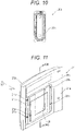
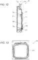
- one antenna 321 is arranged in the reagent installing unit 316, as shown in Fig. 21 .
- the antenna 321 is attached to a housing 316a by having a stopping portion 21a stop at the cutout 216a of the housing 316a of the reagent installing unit 316.
- the housing 316a of the second embodiment does not include the cutout 116a of the first embodiment.
- the transmission output from the reader/writer substrate 317a to the antenna substrate 321b is set so that the antenna 321 emits the short distance read electric wave in the range G (see Fig. 23 ) by the CPU 2a in step S226.
- the set value of the set value storing portion 317d of the reader/writer substrate 317a is set by the CPU 2a so that the read range of the antenna 321 becomes small.
- step S432 the long distance read electric wave in the range H (short distance read electric wave in the range G) is emitted from the antenna 321 to the IC tag 25 of the R1 reagent container 22 (IC tag 26 of the R2 reagent container 24) of the write target by the control of the CPU 2a.
- steps S413 to S417 of the first embodiment shown in Fig. 20 are executed, and the process proceeds to step S5 shown in Fig. 18 .
- the short distance antenna 20 and the long distance antenna 21 are both arranged at the outer peripheral side of the R2 installing portion 19 has been described in the first and second embodiments, but the present invention is not limited thereto.
- the antenna (electric wave emitting portion) may be arranged at the inner peripheral side of the R1 installing portion. In this case, the device main body can be suppressed from becoming large as the region on the outer peripheral side of the R2 installing portion does not need to be ensured for the electric wave emitting portion.
- the transmission output from the reader/writer substrate 17a to the antenna substrate 18b is set so that the antenna 18 emits the short distance read electric wave in the range A (see Fig. 6 ) by the CPU 2a in step S206.
- the set value of the set value storing portion 17c of the reader/writer substrate 17a is set by the CPU 2a so that the read range of the antenna 18 becomes small.
- R1/R3 installing portion 161 and the R2 installing portion 162 are arranged in a substantially circular ring shape
- the present invention is not limited thereto.
- the R1/R3 installing portion and the R2 installing portion may be arranged to extend linearly in a predetermined direction parallel to each other.
Landscapes
- Physics & Mathematics (AREA)
- Health & Medical Sciences (AREA)
- Life Sciences & Earth Sciences (AREA)
- Chemical & Material Sciences (AREA)
- Analytical Chemistry (AREA)
- Biochemistry (AREA)
- General Health & Medical Sciences (AREA)
- General Physics & Mathematics (AREA)
- Immunology (AREA)
- Pathology (AREA)
- Automatic Analysis And Handling Materials Therefor (AREA)
Claims (15)
- Analyseur d'échantillon (1) pour l'analyse d'un échantillon en utilisant un réactif dans un récipient de réactif comprenant :une première unité de maintien de récipient de réactif (19) configurée pour maintenir un premier récipient de réactif (24) attaché à une première étiquette électronique (26) sur laquelle sont enregistrées des informations de réactif concernant un réactif ;une seconde unité de maintien de récipient de réactif (18) configurée pour maintenir un second récipient de réactif (22) attaché à une seconde étiquette électronique (25) sur laquelle sont enregistrées des informations de réactif concernant un réactif, et étant agencée sur un côté périphérique intérieur de la première unité de maintien de récipient de réactif ;une antenne (21) agencée sur un côté périphérique extérieur de la seconde unité de maintien de récipient de réactif (19) et étant configurée pour recevoir des ondes électriques respectives de la première étiquette électronique (26) du premier récipient de réactif (24) et de la seconde étiquette électronique (26) du second récipient de réactif (22), etune unité d'acquisition d'informations de réactif configurée pour acquérir les informations de réactif enregistrées dans la première étiquette électronique (26) sur la base de l'onde électrique reçue par l'antenne (21) depuis la première étiquette électronique (26), et pour acquérir les informations de réactif enregistrées dans la seconde étiquette électronique (25) sur la base de l'onde électrique reçue par l'antenne (21) depuis la seconde étiquette électronique (26), dans lequella première unité de maintien de récipient de réactif (19) maintient une pluralité de premiers récipients de réactif (24) dans un état aligné ; etl'analyseur d'échantillon comprend en outre :une unité d'entraînement (16e) configurée pour déplacer la première unité de maintien de récipient de réactif (19) ; etune unité de commande (2a) configurée pour commander l'unité d'entraînement (16e) afin qu'elle positionne un espacement (F) entre des premiers récipients de réactif (24) adjacents de la première unité de maintien de récipient de réactif (19) dans une région à travers laquelle la seconde étiquette électronique (25) et l'antenne (21) se font face, lorsque l'antenne (21) reçoit l'onde électrique de la seconde étiquette électronique (25) du second récipient de réactif (22).
- Analyseur d'échantillon (1) selon la revendication 1, dans lequel l'antenne (21) est fixée dans une position prédéterminée,l'unité d'entraînement (16e, 16d) est configurée pour déplacer la première unité de maintien de récipient de réactif et la seconde unité de maintien de récipient de réactif ; etl'unité de commande (2a) est configurée pour commander l'unité d'entraînement (16e, 16d) afin qu'elle déplace la première unité de maintien de récipient de réactif (19) et la seconde unité de maintien de récipient de réactif (18) par rapport à l'antenne (21) fixée dans la position prédéterminée de sorte que la seconde étiquette électronique (25) se trouve dans une position faisant face à l'antenne (21) et que l'espacement se trouve dans la région lorsque l'antenne (21) reçoit l'onde électrique de la seconde étiquette électronique (25) du second récipient de réactif (22).
- Analyseur d'échantillon (1) selon la revendication 2, dans lequella seconde unité de maintien de récipient de réactif (18) est configurée pour maintenir une pluralité de seconds récipients de réactif (22), etlorsque l'antenne (21) reçoit l'onde électrique de la seconde étiquette électronique (25) d'un de la pluralité de seconds récipients de réactif (22), l'unité de commande (2a) est configurée pour commander l'unité d'entraînement (16e, 16d) afin qu'elle déplace la seconde unité de maintien de récipient de réactif (18) de sorte que la seconde étiquette électronique (25) d'une cible lue attachée à l'un de la pluralité de seconds récipients de réactif (22) se trouve dans la position faisant face à l'antenne.
- Analyseur d'échantillon (1) selon la revendication 3, dans lequella première unité de maintien de récipient de réactif (19) est configurée pour maintenir la pluralité de premiers récipients de réactif (24) à intervalles égaux, etla seconde unité de maintien de récipient de réactif (18) est configurée pour maintenir la pluralité de seconds récipients de réactif (22) à intervalles égaux.
- Analyseur d'échantillon (1) selon l'une quelconque des revendications 1 à 4, dans lequella première unité de maintien de récipient de réactif (19) est réalisée en une forme sensiblement circulaire en vue en plan ;la seconde unité de maintien de récipient de réactif (18) est réalisée en une forme sensiblement circulaire sur le côté périphérique intérieur de la première unité de maintien de récipient de réactif lorsqu'elle est observée en vue en plan.
- Analyseur d'échantillon (1) selon la revendication 5, dans lequella première étiquette électronique (26) est attachée à un côté extérieur du premier récipient de réactif (24) ; etla seconde étiquette électronique (25) est attachée à un côté extérieur du second récipient de réactif (22).
- Analyseur d'échantillon (1) selon l'une quelconque des revendications 1 à 6, dans lequel l'unité de commande (2a) est configurée pour déterminer si l'antenne (21) a reçu l'onde électrique de l'étiquette électronique d'une cible lue.
- Analyseur d'échantillon (1) selon l'une quelconque des revendications 1 à 7, comprenant en outre une unité d'installation de réactif (16) qui loge la première unité de maintien de récipient de réactif (19), la seconde unité de maintien de récipient de réactif (18) et l'antenne (21).
- Analyseur d'échantillon (1) selon la revendication 8, dans lequell'unité d'installation de réactif (16) inclut un logement (16a) présentant une forme sensiblement cylindrique et une partie formant couvercle agencée pour couvrir le logement (16a) depuis un côté supérieur, etle logement (16a) loge la première unité de maintien de récipient de réactif (19), la seconde unité de maintien de récipient de réactif (18) et l'antenne (21).
- Analyseur d'échantillon (1) selon la revendication 9, dans lequel
un élément de Peltier et un ventilateur (16f) pour le refroidissement du premier récipient de réactif (24) de la première unité de maintien de récipient de réactif (19) et du second récipient de réactif (22) de la seconde unité de maintien de récipient de réactif (18) sont agencés sur un fond du logement (16a). - Analyseur d'échantillon (1) selon l'une quelconque des revendications 1 à 10, dans lequel
l'antenne (21) inclut un substrat d'antenne (21b) et un élément formant couvercle (21d) pour la couverture du substrat d'antenne (21b). - Analyseur d'échantillon (1) selon la revendication 11, dans lequel
l'élément formant couvercle (21b) est réalisé en une résine capable de transmettre une onde électrique. - Analyseur d'échantillon (1) selon l'une quelconque des revendications 1 à 12, dans lequel
chacune de la première étiquette électronique (26) et de la seconde étiquette électronique (25) stocke un ID unique pour l'identification de l'étiquette électronique. - Analyseur d'échantillon (1) selon l'une quelconque des revendications 1 à 13, dans lequel
chacune de la première étiquette électronique (26) et de la seconde étiquette électronique (25) inclut une région en lecture seule pour l'enregistrement d'un élément de mesure, d'un numéro de lot, d'un numéro de série et d'un type de réactif, et une région inscriptible pour l'enregistrement d'une quantité restante d'un réactif et d'une date d'expiration d'utilisation. - Analyseur d'échantillon (1) selon l'une quelconque des revendications 1 à 14, dans lequell'antenne (21) est configurée pour émettre une pluralité d'ondes électriques présentant des portées qui diffèrent mutuellement, etl'unité de commande (2a) commute l'onde électrique émise par l'antenne (21) selon une cible lue qui est la première étiquette électronique (26) ou la seconde étiquette électronique (25).
Applications Claiming Priority (2)
| Application Number | Priority Date | Filing Date | Title |
|---|---|---|---|
| JP2010062097A JP5558149B2 (ja) | 2010-03-18 | 2010-03-18 | 検体分析装置 |
| JP2010068422A JP5558153B2 (ja) | 2010-03-24 | 2010-03-24 | 検体分析装置 |
Publications (3)
| Publication Number | Publication Date |
|---|---|
| EP2367013A2 EP2367013A2 (fr) | 2011-09-21 |
| EP2367013A3 EP2367013A3 (fr) | 2015-09-09 |
| EP2367013B1 true EP2367013B1 (fr) | 2022-06-22 |
Family
ID=44166442
Family Applications (1)
| Application Number | Title | Priority Date | Filing Date |
|---|---|---|---|
| EP11158794.5A Active EP2367013B1 (fr) | 2010-03-18 | 2011-03-18 | Analyseur d'échantillon |
Country Status (3)
| Country | Link |
|---|---|
| US (1) | US9869685B2 (fr) |
| EP (1) | EP2367013B1 (fr) |
| CN (1) | CN102221622B (fr) |
Families Citing this family (7)
| Publication number | Priority date | Publication date | Assignee | Title |
|---|---|---|---|---|
| EP2972219B1 (fr) | 2013-03-15 | 2022-01-19 | Abbott Laboratories | Gestionnaire de réactif automatisé de système analyseur de diagnostic |
| WO2014144870A2 (fr) | 2013-03-15 | 2014-09-18 | Abbott Laboratories | Système de blocage de lumière pour un analyseur de diagnostic |
| US9632103B2 (en) | 2013-03-15 | 2017-04-25 | Abbott Laboraties | Linear track diagnostic analyzer |
| US9835640B2 (en) | 2015-02-13 | 2017-12-05 | Abbott Laboratories | Automated storage modules for diagnostic analyzer liquids and related systems and methods |
| CN111381061B (zh) * | 2018-12-27 | 2024-01-02 | 深圳迈瑞生物医疗电子股份有限公司 | 一种试剂管理方法、试剂供应装置及血液细胞分析仪 |
| EP4224165A4 (fr) * | 2020-09-29 | 2024-10-23 | Hitachi High-Tech Corporation | Analyseur automatisé |
| CN113985045A (zh) * | 2021-10-29 | 2022-01-28 | 深圳迈瑞动物医疗科技有限公司 | 样本分析仪及试剂管理方法 |
Family Cites Families (13)
| Publication number | Priority date | Publication date | Assignee | Title |
|---|---|---|---|---|
| US5051238A (en) * | 1987-11-20 | 1991-09-24 | Hitachi, Ltd. | Automatic analyzing system |
| IL94212A0 (en) * | 1989-07-24 | 1991-01-31 | Tri Tech Partners And Triton B | Automated analytical apparatus and method |
| US5500651A (en) * | 1994-06-24 | 1996-03-19 | Texas Instruments Incorporated | System and method for reading multiple RF-ID transponders |
| JPH10107726A (ja) | 1996-10-03 | 1998-04-24 | Hitachi Ltd | 送信出力切り替え無線中継装通信システム |
| JP4386163B2 (ja) * | 2003-05-19 | 2009-12-16 | 日本電気株式会社 | 在庫管理および納入先在庫量保証サービスの提供システムとその方法 |
| JP4130905B2 (ja) * | 2003-06-23 | 2008-08-13 | 株式会社日立ハイテクノロジーズ | 自動分析装置 |
| JP4736658B2 (ja) | 2005-09-14 | 2011-07-27 | 株式会社豊田中央研究所 | 漏れ波アンテナ |
| JP5199548B2 (ja) * | 2006-05-26 | 2013-05-15 | ベックマン コールター, インコーポレイテッド | 備品管理システム |
| JP4817181B2 (ja) | 2006-07-13 | 2011-11-16 | シスメックス株式会社 | 検体分析装置および識別子読取方法 |
| JP4861139B2 (ja) | 2006-11-30 | 2012-01-25 | 株式会社東芝 | 車両監視システムおよび車両監視方法 |
| JP2008261753A (ja) | 2007-04-12 | 2008-10-30 | Olympus Corp | 試薬容器、試薬収納庫、および自動分析装置 |
| JP4693821B2 (ja) | 2007-08-24 | 2011-06-01 | 株式会社東芝 | 自動改札装置 |
| JP2009210444A (ja) * | 2008-03-05 | 2009-09-17 | Hitachi High-Technologies Corp | 自動分析装置 |
-
2011
- 2011-03-18 US US13/051,445 patent/US9869685B2/en not_active Expired - Fee Related
- 2011-03-18 EP EP11158794.5A patent/EP2367013B1/fr active Active
- 2011-03-18 CN CN201110066018.8A patent/CN102221622B/zh active Active
Also Published As
| Publication number | Publication date |
|---|---|
| US9869685B2 (en) | 2018-01-16 |
| EP2367013A2 (fr) | 2011-09-21 |
| CN102221622B (zh) | 2014-07-23 |
| US20110229374A1 (en) | 2011-09-22 |
| CN102221622A (zh) | 2011-10-19 |
| EP2367013A3 (fr) | 2015-09-09 |
Similar Documents
| Publication | Publication Date | Title |
|---|---|---|
| US10062955B2 (en) | Sample analyzer and reagent information obtaining method | |
| EP2367013B1 (fr) | Analyseur d'échantillon | |
| US10302666B2 (en) | Specimen analyzer and specimen analyzing method | |
| CN1932521B (zh) | 自动分析装置 | |
| US8430321B2 (en) | Sample analyzer and reagent information writing method | |
| US8318499B2 (en) | System for managing inventories of reagents | |
| US8926901B2 (en) | Sample analyzer | |
| JP2004093518A (ja) | 検体指示情報作成システム及び検体ラック | |
| JP2008203007A (ja) | 自動分析装置 | |
| EP2367010A2 (fr) | Analyseur d'échantillon | |
| EP2367014B1 (fr) | Analyseur d'échantillons et procédé pour obtenir des informations sur les réactifs | |
| JP5558149B2 (ja) | 検体分析装置 | |
| JP5558153B2 (ja) | 検体分析装置 | |
| JP5795999B2 (ja) | 自動分析装置 | |
| JP7066423B2 (ja) | 自動分析装置 | |
| CN111209762A (zh) | 信息识别装置、系统及识别方法 | |
| JP2025035358A (ja) | 自動分析装置及び自動分析システム | |
| JPH03289566A (ja) | 自動化学分析装置 |
Legal Events
| Date | Code | Title | Description |
|---|---|---|---|
| PUAI | Public reference made under article 153(3) epc to a published international application that has entered the european phase |
Free format text: ORIGINAL CODE: 0009012 |
|
| AK | Designated contracting states |
Kind code of ref document: A2 Designated state(s): AL AT BE BG CH CY CZ DE DK EE ES FI FR GB GR HR HU IE IS IT LI LT LU LV MC MK MT NL NO PL PT RO RS SE SI SK SM TR |
|
| AX | Request for extension of the european patent |
Extension state: BA ME |
|
| PUAL | Search report despatched |
Free format text: ORIGINAL CODE: 0009013 |
|
| AK | Designated contracting states |
Kind code of ref document: A3 Designated state(s): AL AT BE BG CH CY CZ DE DK EE ES FI FR GB GR HR HU IE IS IT LI LT LU LV MC MK MT NL NO PL PT RO RS SE SI SK SM TR |
|
| AX | Request for extension of the european patent |
Extension state: BA ME |
|
| RIC1 | Information provided on ipc code assigned before grant |
Ipc: G06K 7/10 20060101ALI20150805BHEP Ipc: G01N 35/04 20060101AFI20150805BHEP Ipc: G01N 35/00 20060101ALI20150805BHEP |
|
| 17P | Request for examination filed |
Effective date: 20160225 |
|
| RBV | Designated contracting states (corrected) |
Designated state(s): AL AT BE BG CH CY CZ DE DK EE ES FI FR GB GR HR HU IE IS IT LI LT LU LV MC MK MT NL NO PL PT RO RS SE SI SK SM TR |
|
| STAA | Information on the status of an ep patent application or granted ep patent |
Free format text: STATUS: EXAMINATION IS IN PROGRESS |
|
| 17Q | First examination report despatched |
Effective date: 20200414 |
|
| GRAP | Despatch of communication of intention to grant a patent |
Free format text: ORIGINAL CODE: EPIDOSNIGR1 |
|
| STAA | Information on the status of an ep patent application or granted ep patent |
Free format text: STATUS: GRANT OF PATENT IS INTENDED |
|
| INTG | Intention to grant announced |
Effective date: 20220107 |
|
| RIN1 | Information on inventor provided before grant (corrected) |
Inventor name: TOKUNAGA, KAZUTOSHI |
|
| GRAS | Grant fee paid |
Free format text: ORIGINAL CODE: EPIDOSNIGR3 |
|
| GRAA | (expected) grant |
Free format text: ORIGINAL CODE: 0009210 |
|
| STAA | Information on the status of an ep patent application or granted ep patent |
Free format text: STATUS: THE PATENT HAS BEEN GRANTED |
|
| AK | Designated contracting states |
Kind code of ref document: B1 Designated state(s): AL AT BE BG CH CY CZ DE DK EE ES FI FR GB GR HR HU IE IS IT LI LT LU LV MC MK MT NL NO PL PT RO RS SE SI SK SM TR |
|
| REG | Reference to a national code |
Ref country code: GB Ref legal event code: FG4D |
|
| REG | Reference to a national code |
Ref country code: CH Ref legal event code: EP |
|
| REG | Reference to a national code |
Ref country code: DE Ref legal event code: R096 Ref document number: 602011073022 Country of ref document: DE |
|
| REG | Reference to a national code |
Ref country code: AT Ref legal event code: REF Ref document number: 1500087 Country of ref document: AT Kind code of ref document: T Effective date: 20220715 |
|
| REG | Reference to a national code |
Ref country code: IE Ref legal event code: FG4D |
|
| REG | Reference to a national code |
Ref country code: LT Ref legal event code: MG9D |
|
| REG | Reference to a national code |
Ref country code: NL Ref legal event code: MP Effective date: 20220622 |
|
| PG25 | Lapsed in a contracting state [announced via postgrant information from national office to epo] |
Ref country code: SE Free format text: LAPSE BECAUSE OF FAILURE TO SUBMIT A TRANSLATION OF THE DESCRIPTION OR TO PAY THE FEE WITHIN THE PRESCRIBED TIME-LIMIT Effective date: 20220622 Ref country code: NO Free format text: LAPSE BECAUSE OF FAILURE TO SUBMIT A TRANSLATION OF THE DESCRIPTION OR TO PAY THE FEE WITHIN THE PRESCRIBED TIME-LIMIT Effective date: 20220922 Ref country code: LT Free format text: LAPSE BECAUSE OF FAILURE TO SUBMIT A TRANSLATION OF THE DESCRIPTION OR TO PAY THE FEE WITHIN THE PRESCRIBED TIME-LIMIT Effective date: 20220622 Ref country code: HR Free format text: LAPSE BECAUSE OF FAILURE TO SUBMIT A TRANSLATION OF THE DESCRIPTION OR TO PAY THE FEE WITHIN THE PRESCRIBED TIME-LIMIT Effective date: 20220622 Ref country code: GR Free format text: LAPSE BECAUSE OF FAILURE TO SUBMIT A TRANSLATION OF THE DESCRIPTION OR TO PAY THE FEE WITHIN THE PRESCRIBED TIME-LIMIT Effective date: 20220923 Ref country code: FI Free format text: LAPSE BECAUSE OF FAILURE TO SUBMIT A TRANSLATION OF THE DESCRIPTION OR TO PAY THE FEE WITHIN THE PRESCRIBED TIME-LIMIT Effective date: 20220622 Ref country code: BG Free format text: LAPSE BECAUSE OF FAILURE TO SUBMIT A TRANSLATION OF THE DESCRIPTION OR TO PAY THE FEE WITHIN THE PRESCRIBED TIME-LIMIT Effective date: 20220922 |
|
| REG | Reference to a national code |
Ref country code: AT Ref legal event code: MK05 Ref document number: 1500087 Country of ref document: AT Kind code of ref document: T Effective date: 20220622 |
|
| PG25 | Lapsed in a contracting state [announced via postgrant information from national office to epo] |
Ref country code: RS Free format text: LAPSE BECAUSE OF FAILURE TO SUBMIT A TRANSLATION OF THE DESCRIPTION OR TO PAY THE FEE WITHIN THE PRESCRIBED TIME-LIMIT Effective date: 20220622 Ref country code: LV Free format text: LAPSE BECAUSE OF FAILURE TO SUBMIT A TRANSLATION OF THE DESCRIPTION OR TO PAY THE FEE WITHIN THE PRESCRIBED TIME-LIMIT Effective date: 20220622 |
|
| PG25 | Lapsed in a contracting state [announced via postgrant information from national office to epo] |
Ref country code: NL Free format text: LAPSE BECAUSE OF FAILURE TO SUBMIT A TRANSLATION OF THE DESCRIPTION OR TO PAY THE FEE WITHIN THE PRESCRIBED TIME-LIMIT Effective date: 20220622 |
|
| PG25 | Lapsed in a contracting state [announced via postgrant information from national office to epo] |
Ref country code: SM Free format text: LAPSE BECAUSE OF FAILURE TO SUBMIT A TRANSLATION OF THE DESCRIPTION OR TO PAY THE FEE WITHIN THE PRESCRIBED TIME-LIMIT Effective date: 20220622 Ref country code: SK Free format text: LAPSE BECAUSE OF FAILURE TO SUBMIT A TRANSLATION OF THE DESCRIPTION OR TO PAY THE FEE WITHIN THE PRESCRIBED TIME-LIMIT Effective date: 20220622 Ref country code: RO Free format text: LAPSE BECAUSE OF FAILURE TO SUBMIT A TRANSLATION OF THE DESCRIPTION OR TO PAY THE FEE WITHIN THE PRESCRIBED TIME-LIMIT Effective date: 20220622 Ref country code: PT Free format text: LAPSE BECAUSE OF FAILURE TO SUBMIT A TRANSLATION OF THE DESCRIPTION OR TO PAY THE FEE WITHIN THE PRESCRIBED TIME-LIMIT Effective date: 20221024 Ref country code: ES Free format text: LAPSE BECAUSE OF FAILURE TO SUBMIT A TRANSLATION OF THE DESCRIPTION OR TO PAY THE FEE WITHIN THE PRESCRIBED TIME-LIMIT Effective date: 20220622 Ref country code: EE Free format text: LAPSE BECAUSE OF FAILURE TO SUBMIT A TRANSLATION OF THE DESCRIPTION OR TO PAY THE FEE WITHIN THE PRESCRIBED TIME-LIMIT Effective date: 20220622 Ref country code: CZ Free format text: LAPSE BECAUSE OF FAILURE TO SUBMIT A TRANSLATION OF THE DESCRIPTION OR TO PAY THE FEE WITHIN THE PRESCRIBED TIME-LIMIT Effective date: 20220622 Ref country code: AT Free format text: LAPSE BECAUSE OF FAILURE TO SUBMIT A TRANSLATION OF THE DESCRIPTION OR TO PAY THE FEE WITHIN THE PRESCRIBED TIME-LIMIT Effective date: 20220622 |
|
| PG25 | Lapsed in a contracting state [announced via postgrant information from national office to epo] |
Ref country code: PL Free format text: LAPSE BECAUSE OF FAILURE TO SUBMIT A TRANSLATION OF THE DESCRIPTION OR TO PAY THE FEE WITHIN THE PRESCRIBED TIME-LIMIT Effective date: 20220622 Ref country code: IS Free format text: LAPSE BECAUSE OF FAILURE TO SUBMIT A TRANSLATION OF THE DESCRIPTION OR TO PAY THE FEE WITHIN THE PRESCRIBED TIME-LIMIT Effective date: 20221022 |
|
| REG | Reference to a national code |
Ref country code: DE Ref legal event code: R097 Ref document number: 602011073022 Country of ref document: DE |
|
| PG25 | Lapsed in a contracting state [announced via postgrant information from national office to epo] |
Ref country code: AL Free format text: LAPSE BECAUSE OF FAILURE TO SUBMIT A TRANSLATION OF THE DESCRIPTION OR TO PAY THE FEE WITHIN THE PRESCRIBED TIME-LIMIT Effective date: 20220622 |
|
| PG25 | Lapsed in a contracting state [announced via postgrant information from national office to epo] |
Ref country code: DK Free format text: LAPSE BECAUSE OF FAILURE TO SUBMIT A TRANSLATION OF THE DESCRIPTION OR TO PAY THE FEE WITHIN THE PRESCRIBED TIME-LIMIT Effective date: 20220622 |
|
| PLBE | No opposition filed within time limit |
Free format text: ORIGINAL CODE: 0009261 |
|
| STAA | Information on the status of an ep patent application or granted ep patent |
Free format text: STATUS: NO OPPOSITION FILED WITHIN TIME LIMIT |
|
| 26N | No opposition filed |
Effective date: 20230323 |
|
| PG25 | Lapsed in a contracting state [announced via postgrant information from national office to epo] |
Ref country code: SI Free format text: LAPSE BECAUSE OF FAILURE TO SUBMIT A TRANSLATION OF THE DESCRIPTION OR TO PAY THE FEE WITHIN THE PRESCRIBED TIME-LIMIT Effective date: 20220622 |
|
| PG25 | Lapsed in a contracting state [announced via postgrant information from national office to epo] |
Ref country code: MC Free format text: LAPSE BECAUSE OF FAILURE TO SUBMIT A TRANSLATION OF THE DESCRIPTION OR TO PAY THE FEE WITHIN THE PRESCRIBED TIME-LIMIT Effective date: 20220622 |
|
| REG | Reference to a national code |
Ref country code: CH Ref legal event code: PL |
|
| REG | Reference to a national code |
Ref country code: BE Ref legal event code: MM Effective date: 20230331 |
|
| PG25 | Lapsed in a contracting state [announced via postgrant information from national office to epo] |
Ref country code: LU Free format text: LAPSE BECAUSE OF NON-PAYMENT OF DUE FEES Effective date: 20230318 |
|
| REG | Reference to a national code |
Ref country code: IE Ref legal event code: MM4A |
|
| PG25 | Lapsed in a contracting state [announced via postgrant information from national office to epo] |
Ref country code: LI Free format text: LAPSE BECAUSE OF NON-PAYMENT OF DUE FEES Effective date: 20230331 Ref country code: IT Free format text: LAPSE BECAUSE OF FAILURE TO SUBMIT A TRANSLATION OF THE DESCRIPTION OR TO PAY THE FEE WITHIN THE PRESCRIBED TIME-LIMIT Effective date: 20220622 Ref country code: IE Free format text: LAPSE BECAUSE OF NON-PAYMENT OF DUE FEES Effective date: 20230318 Ref country code: CH Free format text: LAPSE BECAUSE OF NON-PAYMENT OF DUE FEES Effective date: 20230331 |
|
| PG25 | Lapsed in a contracting state [announced via postgrant information from national office to epo] |
Ref country code: BE Free format text: LAPSE BECAUSE OF NON-PAYMENT OF DUE FEES Effective date: 20230331 |
|
| PG25 | Lapsed in a contracting state [announced via postgrant information from national office to epo] |
Ref country code: BG Free format text: LAPSE BECAUSE OF FAILURE TO SUBMIT A TRANSLATION OF THE DESCRIPTION OR TO PAY THE FEE WITHIN THE PRESCRIBED TIME-LIMIT Effective date: 20220622 |
|
| PG25 | Lapsed in a contracting state [announced via postgrant information from national office to epo] |
Ref country code: BG Free format text: LAPSE BECAUSE OF FAILURE TO SUBMIT A TRANSLATION OF THE DESCRIPTION OR TO PAY THE FEE WITHIN THE PRESCRIBED TIME-LIMIT Effective date: 20220622 |
|
| PGFP | Annual fee paid to national office [announced via postgrant information from national office to epo] |
Ref country code: DE Payment date: 20250128 Year of fee payment: 15 |
|
| PGFP | Annual fee paid to national office [announced via postgrant information from national office to epo] |
Ref country code: FR Payment date: 20250210 Year of fee payment: 15 |
|
| PGFP | Annual fee paid to national office [announced via postgrant information from national office to epo] |
Ref country code: GB Payment date: 20250130 Year of fee payment: 15 |
|
| PG25 | Lapsed in a contracting state [announced via postgrant information from national office to epo] |
Ref country code: CY Free format text: LAPSE BECAUSE OF FAILURE TO SUBMIT A TRANSLATION OF THE DESCRIPTION OR TO PAY THE FEE WITHIN THE PRESCRIBED TIME-LIMIT; INVALID AB INITIO Effective date: 20110318 |
|
| PG25 | Lapsed in a contracting state [announced via postgrant information from national office to epo] |
Ref country code: HU Free format text: LAPSE BECAUSE OF FAILURE TO SUBMIT A TRANSLATION OF THE DESCRIPTION OR TO PAY THE FEE WITHIN THE PRESCRIBED TIME-LIMIT; INVALID AB INITIO Effective date: 20110318 |
|
| PG25 | Lapsed in a contracting state [announced via postgrant information from national office to epo] |
Ref country code: TR Free format text: LAPSE BECAUSE OF FAILURE TO SUBMIT A TRANSLATION OF THE DESCRIPTION OR TO PAY THE FEE WITHIN THE PRESCRIBED TIME-LIMIT Effective date: 20220622 |