EP2367075B1 - Aufzugskrone für Uhren - Google Patents
Aufzugskrone für Uhren Download PDFInfo
- Publication number
- EP2367075B1 EP2367075B1 EP10156794.9A EP10156794A EP2367075B1 EP 2367075 B1 EP2367075 B1 EP 2367075B1 EP 10156794 A EP10156794 A EP 10156794A EP 2367075 B1 EP2367075 B1 EP 2367075B1
- Authority
- EP
- European Patent Office
- Prior art keywords
- crown
- ring
- elastically deformable
- head
- winding
- Prior art date
- Legal status (The legal status is an assumption and is not a legal conclusion. Google has not performed a legal analysis and makes no representation as to the accuracy of the status listed.)
- Active
Links
Images
Classifications
-
- G—PHYSICS
- G04—HOROLOGY
- G04B—MECHANICALLY-DRIVEN CLOCKS OR WATCHES; MECHANICAL PARTS OF CLOCKS OR WATCHES IN GENERAL; TIME PIECES USING THE POSITION OF THE SUN, MOON OR STARS
- G04B3/00—Normal winding of clockworks by hand or mechanically; Winding up several mainsprings or driving weights simultaneously
- G04B3/06—Keys or the like with means preventing overwinding
Definitions
- the present invention relates to a winding crown for a timepiece. More specifically, the present invention relates to such a ring guard against any parasitic torque resistant.
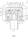
- a crown for a timepiece of the type mentioned in the preamble is known from the European patent application EP 1 586 960 in the name of the Claimant. Such a crown is shown in section at figure 1 attached to this patent application.
- this ring has a symmetry of rotation axis X1 and is hollow so as to define a housing in which are housed the various elements of the disengaging mechanism.
- these elements there is in particular a hollow support element 2 whose dimensions are adjusted to those of the hollow inner housing of the ring 1 and which is closed on one side by a bottom 4.
- Each of the springs 6 is of the flat spring type. It comprises a central base 8 of general shape close to that of a square and pierced with a hole 10 also of substantially square shape centered on the general axis of symmetry X1 of the crown 1.
- Four arms 12 elastically deformable extend from the central base 8 of each of the two springs 6.
- the assembly is completed by a barrel 14 of generally cylindrical shape, a first end facing the center of the movement of the timepiece is intended to receive a winding stem (not shown).
- the barrel 14 comprises a main portion 16 of cylindrical shape surmounted by a head 18 in the form of disc whose diameter is greater than the diameter of the main portion 16.
- the head 18 is itself surmounted by a portion 20 whose transverse dimensions are smaller than those of the main part 16 and which protrudes from the surface of the head 18.
- This projecting portion 20 is centered on the axis of symmetry X1 of the ring 1 and has a contour of square shape complementary to that of the holes 10 of the springs 6 with which this projecting portion 20 is intended to cooperate.
- a rigid element 22 in the form of a ring or washer whose central opening has a diameter greater than the diameter of the head 18 of the barrel 14.
- This rigid ring 22 has a plurality of notches 24 intended to cooperate with the resilient arms 12 of the springs 6. It is arranged against the bottom 4 of the hollow element 2 so that the notches 24 are located opposite the arms 12 of the springs 6.
- An additional washer 26 is provided to support the rigid ring 22 and the barrel 14.
- the washer 26 has an annular shoulder 28 of inside diameter greater than the diameter of the head 18 of the barrel 14 and an outside diameter substantially equal to diameter of the rigid ring 22.
- the height of the annular shoulder 28 of the washer 26 is chosen such that it is equal to or greater than the thickness of the head 18 of the barrel 14, which allows the Shoulder 28 to play the role of spacer.
- the washer 26 further comprises a central opening 30 whose diameter is adjusted to the diameter of the main portion 16 of the barrel 14.
- a reduction ring 32 is mounted after each other, the outside diameter of which is substantially equal to the inside diameter of the support member 2 and an O-ring type ring seal 34 whose diameter outside at rest is substantially greater than the inside diameter of the support member 2.
- flat washer 36 is then provided to close the inner housing of the ring 1.
- a tube 38 is passed through the flat washer 36, the seal 34 and the reduction washer 32 and is fixed on the main part 16 of the barrel 14.
- This tube 38 whose outer diameter is substantially greater than the diameter
- the inside of the O-ring 34 has the function of allowing the crown 1 to be mounted on the middle part of a watch case.
- the ring 1 On its outer surface, the ring 1 comprises a plurality of grooves for facilitating the operation of the ring 1 by the user.
- the ring 1 delimits a hollow inner housing in which is housed the disengaging mechanism.
- This clutch mechanism essentially comprises a rigid ring 22 having on its inner periphery a plurality of notches 24 intended to cooperate with one or more spring elements 6 of generally circular shape to perform the disengaging function.
- the notched ring 22 is integral with the ring 1 while the spring elements 6 are fixed on the barrel 14 on which is screwed a winding stem which acts on the winding mechanism of the mainspring.
- the resisting torque opposed by the spring elements 6 is less than a predetermined value, they are rotated by the rigid ring 22 under the effect of the actuation of the ring 1 by the user. In turn, the spring elements 6 drive the barrel 14 on which they are mounted and therefore the winding stem.
- the resisting torque opposed by the spring elements 6 becomes greater than the predetermined value because the barrel spring is fully armed, said spring elements 6 will deform elastically in response to the actuation of the rigid ring 22 and will escape to the latter by sliding. As a result, the user-operated ring 1 will turn in a vacuum. The barrel spring is thus protected against any excessive winding which could damage it.
- the barrel 14 has at its upper end a protruding portion 20 of shape for example square and fits in a hole, also square, made in the springs 6 by which said springs 6 are secured to said barrel 14.
- a protruding portion 20 of shape for example square and fits in a hole, also square, made in the springs 6 by which said springs 6 are secured to said barrel 14.
- the crown described above has presented a problem. Indeed, as can be understood from the examination of the figure 1 when pressure is exerted on the ring 1, there is nothing to prevent the spring element located highest in the stack of the spring elements 6 from bearing against the bottom 4 of the support element 2. surface contact between the spring element 6 and the bottom 4 of the support element 2 generates a parasitic torque which delays the moment when the resisting torque opposed by the spring elements 6 becomes greater than the predetermined threshold value and where said spring elements 6 will deform elastically in response to the actuation of the rigid ring 22 to escape the latter by sliding. In other words, the clutch can occur after the barrel spring is fully armed, hence serious risks of damaging the movement of the watch.
- the patent document FR 1 571 565 describes a winding crown inside which is driven a bushing whose bottom has an axial opening for the passage of the outer portion of a tigeron.
- the sleeve rests against a scope of the crown so as to provide a housing within which the end of the tigeron protrudes.
- the head of a screw fixed axially to the outer end of the tigeron forms a bearing against which bears the inner edge of an annular spring.
- the patent document EP 1 566 708 discloses a torque limiting winding device comprising a cap-shaped winding crown, provided with a bottom and a tubular portion whose outer wall is provided with splines and the inner wall of spans, the bottom and the portion tubular defining a housing.
- a disengagement member, mounted in the housing, and a winding stem attached to the disengagement member complete the assembly.
- the disengagement member comprises a clutch part comprising a plate disposed in the housing, between the bottom and a bearing surface of the crown, and a clutch plate.
- a coil spring is supported against the clutch disk, so as to generate a force gripping balls between the clutch disc and the plate.
- the patent document FR 1 506 657 discloses a winding device comprising a crown that can be locked on a pendant by a bayonet closure device.
- the inner walls of the recess of the ring have splines for cooperating with the splines of a sleeve for driving the sleeve in rotation.
- the sleeve is secured in rotation with the rod holder via a square fixed by a screw on the rod holder.
- the patent WO 2007/113723 discloses a push-button for a sealed watch case comprising a locking cap screwed onto a head of an actuating screw.
- the cap has an axial extension greater than the head of the screw so as to extend beyond the head of the screw towards the watch case.
- a stop ring is screwed onto the locking cap near the free edge so that the stop ring abuts against the head and against the box respectively in an unlocking and locking configuration.
- the present invention aims to remedy these problems by providing a winding crown which is free of any parasitic friction and which allows to protect the watch movement and in particular the mainspring.
- the present invention relates to a winding crown for a timepiece according to claim 1 attached to the present patent application.
- the present invention provides a winding crown for a timepiece in which an abutment is interposed between the bottom of the ring and the elastically deformable element. This stop prevents the elastically deformable element from coming into contact with the surface of the bottom of the ring when the ring is pressed axially towards the center of the movement of the timepiece. This avoids any parasitic torque, which makes it possible to provide a winding crown with improved operation and to effectively protect the watch movement and in particular the mainspring.
- the contact surface between the abutment and the bottom of the ring is less than the contact area between the elastically deformable element and the same bottom, so that the parasitic torque induced by the stop is substantially less than the parasitic torque. induced by the elastic element.
- the abutment is constituted by a tenon comprising a head partially housed in a recess formed in the bottom of the crown and protruding from the recess on a height which defines the spacing between the spring and the background of the crown.
- the head of the tenon is of conical shape.
- the conical shape of the tenon head also contributes to a reduction of the contact surface between this tenon and the bottom of the the protruding portion 68 is slightly greater than the thickness of the three springs 50 joined together.
- a sleeve 70 is provided to support the notched ring 60 and the barrel 62.
- the sleeve 70 has an annular shoulder 72 of inner diameter greater than the diameter of the head 66 of the barrel 62 and an outer diameter substantially equal to the diameter
- the height of the annular shoulder 72 of the sleeve 70 is chosen such that it is equal to or greater than the thickness of the head 66 of the barrel 62, which allows the shoulder 28 to play the role of spacer.
- the bushing 70 further comprises a central opening 74 whose diameter is adjusted to the diameter of a tube 76 fixed on the main portion 64 of the barrel 62 and whose function is to allow the mounting of the crown 40 on the middle part of the barrel. a watch box.
- a first and a second circular grooves 78 and 80 are formed in the sleeve 70 and each receive an O-ring type seal respectively 82 and 84.
- the first seal 82 seals between the skirt 44 of the ring 40 and the sleeve 70 and the second seal 84 seals between the sleeve 70 and the tube 76.
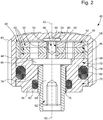
- the pin 86 is interposed between the bottom 42 of the ring 40 and the highest spring in the stack of three springs 50 a pin 86 which acts as a shim or stop to prevent the spring 50 comes into contact with the bottom 42 of the ring 40.
- the pin 86 comprises a head 88 partially housed in a recess 90 formed in the bottom 42 of the ring 40 and whose diameter is greater than the dimensions of the hole 54 of the spring 50.
- the head 88 of the pin 86 protrudes from the recess 90 to a height less than or equal to the height of a shoulder 92 against which the notched ring 60 bears.
- the head 88 of the tenon 86 is extended by a foot 94 which is guided freely in the projecting portion 68 which overcomes the head 66 of the barrel 62. It will be understood that the contact surface between the head 88 of the post 86 and the bottom 42 of the crown 40 is less than the surface of contact between the spring 56 and the same bottom 42, so that the parasitic torque induced by the pin 86 is substantially less than the parasitic torque induced by the spring 56. In addition, the conical shape of the head 88 of the pin 86 also contributes to a reduction of the contact surface between the pin 88 and the bottom 42 of the ring 40 and therefore to a limitation of the friction forces between these two parts.
Landscapes
- Physics & Mathematics (AREA)
- General Physics & Mathematics (AREA)
- Electric Clocks (AREA)
Claims (5)
- Aufziehkrone für ein Zeitmessgerät, wobei diese Krone (40) einen Boden (42) und eine Verkleidung (44) umfasst, die ein Innenvolumen begrenzt, in dem mindestens ein elastisch verformbares Element angeordnet ist, wobei ein zwischen das elastisch verformbare Element (50) und den Boden (42) der Krone (40) eingefügter Anschlag vorgesehen ist, um jeglichen Oberflächenkontakt zwischen diesem elastisch verformbaren Element (50) und diesem Boden (42) zu vermeiden, wobei die Krone (40) dadurch gekennzeichnet ist, dass der Anschlag durch einen Zapfen (86) gebildet ist, der einen Kopf (88) aufweist, der teilweise in einer Vertiefung (90) aufgenommen ist, die in dem Boden (42) der Krone (40) ausgebildet ist, und aus der Vertiefung (90) mit einer Höhe vorsteht, die einen Zwischenraum mit dem Boden (42) der Krone (40) definiert, der kleiner als ein Zwischenraum zwischen dem elastisch verformbaren Element (50) und dem Boden (42) der Krone (40) ist.
- Krone nach Anspruch 1, dadurch gekennzeichnet, dass sie mit einem Entkopplungsmechanismus (46) versehen ist, der einen starren Antriebsring (60) umfasst, der mit der Krone (40) fest verbunden ist und mit dem elastisch verformbaren Element (50) zusammenwirkt, wobei dieses elastische Element (50) mit einer Walze (62) fest verbunden ist, deren erstes Ende, das zum Zentrum des Werks des Zeitmessgeräts ausgerichtet ist, dazu bestimmt ist, eine Aufzugwelle aufzunehmen, wobei der starre Ring (60) das elastische verformbare Element (50) in mindestens einer Drehrichtung antreibt, bis das durch das elastische Element (50) ausgeübte Gegendrehmoment einen Schwellenwert überschreitet, oberhalb dessen sich dieses elastische Element (50) in einer Weise verformt, dass seine Antriebsverbindung mit dem starren Ring unterbrochen wird, wobei das elastische verformbare Element (50) hierzu Mittel zum vorübergehenden Koppeln mit dem starren Antriebsring aufweist.
- Aufziehkrone nach einem der Ansprüche 1 oder 2, dadurch gekennzeichnet, dass der Kopf (88) des Zapfens (86) eine konische Form hat.
- Aufziehkrone nach einem der Ansprüche 1 bis 3, dadurch gekennzeichnet, dass der Kopf (88) des Zapfens (86) durch einen Fuß (94) verlängert ist.
- Aufziehkrone nach Anspruch 4, dadurch gekennzeichnet, dass der Fuß (94) des Zapfens (86) in einem vorstehenden Abschnitt (68), der einen Kopf (66) der Walze (62) übersteigt, frei geführt wird.
Priority Applications (5)
| Application Number | Priority Date | Filing Date | Title |
|---|---|---|---|
| EP10156794.9A EP2367075B1 (de) | 2010-03-17 | 2010-03-17 | Aufzugskrone für Uhren |
| CN201110064618.0A CN102193483B (zh) | 2010-03-17 | 2011-03-17 | 钟表的上条表冠 |
| US13/050,368 US8602639B2 (en) | 2010-03-17 | 2011-03-17 | Winding crown for a timepiece |
| JP2011059391A JP5331842B2 (ja) | 2010-03-17 | 2011-03-17 | 腕時計用のクラウン |
| HK12102703.0A HK1162692B (en) | 2010-03-17 | 2012-03-19 | Winding crown for a timepiece |
Applications Claiming Priority (1)
| Application Number | Priority Date | Filing Date | Title |
|---|---|---|---|
| EP10156794.9A EP2367075B1 (de) | 2010-03-17 | 2010-03-17 | Aufzugskrone für Uhren |
Publications (2)
| Publication Number | Publication Date |
|---|---|
| EP2367075A1 EP2367075A1 (de) | 2011-09-21 |
| EP2367075B1 true EP2367075B1 (de) | 2017-07-26 |
Family
ID=42674624
Family Applications (1)
| Application Number | Title | Priority Date | Filing Date |
|---|---|---|---|
| EP10156794.9A Active EP2367075B1 (de) | 2010-03-17 | 2010-03-17 | Aufzugskrone für Uhren |
Country Status (4)
| Country | Link |
|---|---|
| US (1) | US8602639B2 (de) |
| EP (1) | EP2367075B1 (de) |
| JP (1) | JP5331842B2 (de) |
| CN (1) | CN102193483B (de) |
Families Citing this family (6)
| Publication number | Priority date | Publication date | Assignee | Title |
|---|---|---|---|---|
| EP2915012B1 (de) * | 2012-11-02 | 2021-03-31 | Omega SA | Device for the orientation of a screwed element of a timepiece |
| JP6367059B2 (ja) * | 2014-09-09 | 2018-08-01 | セイコーインスツル株式会社 | 時計 |
| EP3805869B1 (de) * | 2019-10-09 | 2025-12-24 | Meco S.A. | Geschraubte krone |
| EP3825777B1 (de) * | 2019-11-21 | 2024-04-24 | Meco S.A. | Korrekturvorrichtung einer armbanduhr und armbanduhrgehäuse |
| EP3828641B1 (de) | 2019-11-29 | 2022-07-20 | Meco S.A. | Drückerkrone für uhr |
| EP4006647B1 (de) * | 2020-11-25 | 2023-05-10 | Meco S.A. | Drückerkrone für uhr |
Citations (3)
| Publication number | Priority date | Publication date | Assignee | Title |
|---|---|---|---|---|
| EP1586960A1 (de) * | 2004-04-14 | 2005-10-19 | Meco S.A. | Krone für eine Uhr mit einer Auskupplungsvorrichtung |
| EP2058713A1 (de) * | 2007-11-08 | 2009-05-13 | Meco S.A. | Krone für Uhr |
| EP2058714A1 (de) * | 2007-11-08 | 2009-05-13 | Meco S.A. | Aufzugskrone für Uhr, die einen Mechanismus mit Drehmomentkupplung umfasst |
Family Cites Families (12)
| Publication number | Priority date | Publication date | Assignee | Title |
|---|---|---|---|---|
| US909515A (en) * | 1908-05-02 | 1909-01-12 | Henry Axtell | Crown for the winding-stems of watches. |
| US951672A (en) * | 1909-12-14 | 1910-03-08 | Henry Axtell | Crown for winding-stems of watches. |
| US2268749A (en) * | 1940-02-14 | 1942-01-06 | Charles B Greenberg | Watch stem bushing |
| US2637987A (en) * | 1947-02-18 | 1953-05-12 | Hil Jon Safety Crown Corp | Overload release coupling |
| US2497935A (en) * | 1947-07-11 | 1950-02-21 | Feurer Bros Inc | Dust-tight watch crown |
| CH470704A (fr) * | 1965-07-14 | 1969-05-14 | Piquerez Sa Ervin | Montre comprenant une couronne rotative, montée sous la glace |
| CH472721A (fr) | 1966-06-14 | 1969-06-30 | Boninchi Sa | Dispositif de commande étanche d'un mécanisme de pièce d'horlogerie logé dans un boîtier |
| CH918367A4 (de) * | 1967-06-28 | 1971-02-26 | ||
| CH691935A5 (de) * | 1997-06-11 | 2001-11-30 | Meco Sa Grenchen | Sicherheitsventil für eine Uhr. |
| CH697270B1 (fr) * | 2004-01-28 | 2008-07-31 | Richemont Int Sa | Dispositif de remontoir. |
| ITFI20060083A1 (it) * | 2006-03-30 | 2007-09-30 | Anonimo S P A | Pulsante ermetico per cassa di orologio |
| JP5044374B2 (ja) * | 2007-11-26 | 2012-10-10 | セイコーインスツル株式会社 | 携帯時計 |
-
2010
- 2010-03-17 EP EP10156794.9A patent/EP2367075B1/de active Active
-
2011
- 2011-03-17 JP JP2011059391A patent/JP5331842B2/ja active Active
- 2011-03-17 CN CN201110064618.0A patent/CN102193483B/zh active Active
- 2011-03-17 US US13/050,368 patent/US8602639B2/en active Active
Patent Citations (3)
| Publication number | Priority date | Publication date | Assignee | Title |
|---|---|---|---|---|
| EP1586960A1 (de) * | 2004-04-14 | 2005-10-19 | Meco S.A. | Krone für eine Uhr mit einer Auskupplungsvorrichtung |
| EP2058713A1 (de) * | 2007-11-08 | 2009-05-13 | Meco S.A. | Krone für Uhr |
| EP2058714A1 (de) * | 2007-11-08 | 2009-05-13 | Meco S.A. | Aufzugskrone für Uhr, die einen Mechanismus mit Drehmomentkupplung umfasst |
Also Published As
| Publication number | Publication date |
|---|---|
| CN102193483B (zh) | 2014-08-13 |
| JP2011197003A (ja) | 2011-10-06 |
| US8602639B2 (en) | 2013-12-10 |
| CN102193483A (zh) | 2011-09-21 |
| JP5331842B2 (ja) | 2013-10-30 |
| EP2367075A1 (de) | 2011-09-21 |
| HK1162692A1 (en) | 2012-08-31 |
| US20110228646A1 (en) | 2011-09-22 |
Similar Documents
| Publication | Publication Date | Title |
|---|---|---|
| EP2058713A1 (de) | Krone für Uhr | |
| EP2058714B1 (de) | Aufzugskrone für Uhr, die einen Mechanismus mit Drehmomentkupplung umfasst | |
| EP2015145B1 (de) | Vertikale Kupplungsvorrichtung für Uhr | |
| EP2718770B1 (de) | Vorrichtung zur ausrichtung der geschraubten aufzugskrone einer uhr | |
| EP3088970B1 (de) | Armbanduhr, die zum befestigen auf einer entfernbaren halterung konzipiert ist | |
| EP2367075A1 (de) | Aufzugskrone für Uhren | |
| EP3451071B1 (de) | Vorrichtung mit drucktaste für uhr | |
| EP1586960A1 (de) | Krone für eine Uhr mit einer Auskupplungsvorrichtung | |
| EP0696978A1 (de) | Vorrichtung zur befestigung eines schuhes an einem fahrradpedal und schuh und pedal für eine derartige vorrichtung | |
| CH705043A2 (fr) | Pièce d'horlogerie portable incluant un bouton-poussoir. | |
| FR3066042A1 (fr) | Dispositif d'arret d'urgence | |
| FR3040131A1 (fr) | Dispositif a ouverture rapide par pression unique d'un couvercle de toilette | |
| EP1975749B1 (de) | Uhr mit elastisch gehaltenem Uhrwerk | |
| EP1853977B1 (de) | Blockierbarer drücker | |
| EP2163466A1 (de) | Intergriertes Scharnier für Klappfahrrad | |
| CH702845A2 (fr) | Couronne de remontage pour pièce d'horlogerie. | |
| EP2824247B1 (de) | Betätigungsknopf für Wasserspülungsmechanismus | |
| EP2945028B1 (de) | Stoßdämpfendes Lager | |
| CH706232A2 (fr) | Dispositif de commande et de réglage comportant une couronne et un poussoir coaxial. | |
| WO2021099737A1 (fr) | Siège d'aéronef | |
| EP2141554A2 (de) | Drücker | |
| EP3302195B1 (de) | Vorrichtung zum mahlen eines würzmittels mithilfe einer mühle sowie mühle mit solch einer mahlvorrichtung | |
| CH708126A2 (fr) | Joint, poussoir et couronne de pièce d'horlogerie. | |
| CH703622A2 (fr) | Poussoir a seuil de declenchement pour piece d'horlogerie. | |
| CH707344A2 (fr) | Palier antichoc et pièce d'horlogerie comportant un tel palier. |
Legal Events
| Date | Code | Title | Description |
|---|---|---|---|
| PUAI | Public reference made under article 153(3) epc to a published international application that has entered the european phase |
Free format text: ORIGINAL CODE: 0009012 |
|
| AK | Designated contracting states |
Kind code of ref document: A1 Designated state(s): AT BE BG CH CY CZ DE DK EE ES FI FR GB GR HR HU IE IS IT LI LT LU LV MC MK MT NL NO PL PT RO SE SI SK SM TR |
|
| AX | Request for extension of the european patent |
Extension state: AL BA ME RS |
|
| 17P | Request for examination filed |
Effective date: 20120321 |
|
| 17Q | First examination report despatched |
Effective date: 20150122 |
|
| GRAP | Despatch of communication of intention to grant a patent |
Free format text: ORIGINAL CODE: EPIDOSNIGR1 |
|
| INTG | Intention to grant announced |
Effective date: 20170511 |
|
| GRAS | Grant fee paid |
Free format text: ORIGINAL CODE: EPIDOSNIGR3 |
|
| GRAA | (expected) grant |
Free format text: ORIGINAL CODE: 0009210 |
|
| AK | Designated contracting states |
Kind code of ref document: B1 Designated state(s): AT BE BG CH CY CZ DE DK EE ES FI FR GB GR HR HU IE IS IT LI LT LU LV MC MK MT NL NO PL PT RO SE SI SK SM TR |
|
| REG | Reference to a national code |
Ref country code: GB Ref legal event code: FG4D Free format text: NOT ENGLISH |
|
| REG | Reference to a national code |
Ref country code: CH Ref legal event code: EP |
|
| REG | Reference to a national code |
Ref country code: AT Ref legal event code: REF Ref document number: 912862 Country of ref document: AT Kind code of ref document: T Effective date: 20170815 |
|
| REG | Reference to a national code |
Ref country code: IE Ref legal event code: FG4D Free format text: LANGUAGE OF EP DOCUMENT: FRENCH |
|
| REG | Reference to a national code |
Ref country code: CH Ref legal event code: NV Representative=s name: ICB INGENIEURS CONSEILS EN BREVETS SA, CH |
|
| REG | Reference to a national code |
Ref country code: DE Ref legal event code: R096 Ref document number: 602010043839 Country of ref document: DE |
|
| REG | Reference to a national code |
Ref country code: NL Ref legal event code: MP Effective date: 20170726 |
|
| REG | Reference to a national code |
Ref country code: LT Ref legal event code: MG4D |
|
| REG | Reference to a national code |
Ref country code: AT Ref legal event code: MK05 Ref document number: 912862 Country of ref document: AT Kind code of ref document: T Effective date: 20170726 |
|
| PG25 | Lapsed in a contracting state [announced via postgrant information from national office to epo] |
Ref country code: SE Free format text: LAPSE BECAUSE OF FAILURE TO SUBMIT A TRANSLATION OF THE DESCRIPTION OR TO PAY THE FEE WITHIN THE PRESCRIBED TIME-LIMIT Effective date: 20170726 Ref country code: FI Free format text: LAPSE BECAUSE OF FAILURE TO SUBMIT A TRANSLATION OF THE DESCRIPTION OR TO PAY THE FEE WITHIN THE PRESCRIBED TIME-LIMIT Effective date: 20170726 Ref country code: NL Free format text: LAPSE BECAUSE OF FAILURE TO SUBMIT A TRANSLATION OF THE DESCRIPTION OR TO PAY THE FEE WITHIN THE PRESCRIBED TIME-LIMIT Effective date: 20170726 Ref country code: HR Free format text: LAPSE BECAUSE OF FAILURE TO SUBMIT A TRANSLATION OF THE DESCRIPTION OR TO PAY THE FEE WITHIN THE PRESCRIBED TIME-LIMIT Effective date: 20170726 Ref country code: LT Free format text: LAPSE BECAUSE OF FAILURE TO SUBMIT A TRANSLATION OF THE DESCRIPTION OR TO PAY THE FEE WITHIN THE PRESCRIBED TIME-LIMIT Effective date: 20170726 Ref country code: AT Free format text: LAPSE BECAUSE OF FAILURE TO SUBMIT A TRANSLATION OF THE DESCRIPTION OR TO PAY THE FEE WITHIN THE PRESCRIBED TIME-LIMIT Effective date: 20170726 Ref country code: NO Free format text: LAPSE BECAUSE OF FAILURE TO SUBMIT A TRANSLATION OF THE DESCRIPTION OR TO PAY THE FEE WITHIN THE PRESCRIBED TIME-LIMIT Effective date: 20171026 |
|
| REG | Reference to a national code |
Ref country code: FR Ref legal event code: PLFP Year of fee payment: 9 |
|
| PG25 | Lapsed in a contracting state [announced via postgrant information from national office to epo] |
Ref country code: PL Free format text: LAPSE BECAUSE OF FAILURE TO SUBMIT A TRANSLATION OF THE DESCRIPTION OR TO PAY THE FEE WITHIN THE PRESCRIBED TIME-LIMIT Effective date: 20170726 Ref country code: GR Free format text: LAPSE BECAUSE OF FAILURE TO SUBMIT A TRANSLATION OF THE DESCRIPTION OR TO PAY THE FEE WITHIN THE PRESCRIBED TIME-LIMIT Effective date: 20171027 Ref country code: LV Free format text: LAPSE BECAUSE OF FAILURE TO SUBMIT A TRANSLATION OF THE DESCRIPTION OR TO PAY THE FEE WITHIN THE PRESCRIBED TIME-LIMIT Effective date: 20170726 Ref country code: ES Free format text: LAPSE BECAUSE OF FAILURE TO SUBMIT A TRANSLATION OF THE DESCRIPTION OR TO PAY THE FEE WITHIN THE PRESCRIBED TIME-LIMIT Effective date: 20170726 Ref country code: IS Free format text: LAPSE BECAUSE OF FAILURE TO SUBMIT A TRANSLATION OF THE DESCRIPTION OR TO PAY THE FEE WITHIN THE PRESCRIBED TIME-LIMIT Effective date: 20171126 Ref country code: BG Free format text: LAPSE BECAUSE OF FAILURE TO SUBMIT A TRANSLATION OF THE DESCRIPTION OR TO PAY THE FEE WITHIN THE PRESCRIBED TIME-LIMIT Effective date: 20171026 |
|
| PG25 | Lapsed in a contracting state [announced via postgrant information from national office to epo] |
Ref country code: CZ Free format text: LAPSE BECAUSE OF FAILURE TO SUBMIT A TRANSLATION OF THE DESCRIPTION OR TO PAY THE FEE WITHIN THE PRESCRIBED TIME-LIMIT Effective date: 20170726 Ref country code: RO Free format text: LAPSE BECAUSE OF FAILURE TO SUBMIT A TRANSLATION OF THE DESCRIPTION OR TO PAY THE FEE WITHIN THE PRESCRIBED TIME-LIMIT Effective date: 20170726 Ref country code: DK Free format text: LAPSE BECAUSE OF FAILURE TO SUBMIT A TRANSLATION OF THE DESCRIPTION OR TO PAY THE FEE WITHIN THE PRESCRIBED TIME-LIMIT Effective date: 20170726 |
|
| REG | Reference to a national code |
Ref country code: DE Ref legal event code: R097 Ref document number: 602010043839 Country of ref document: DE |
|
| PG25 | Lapsed in a contracting state [announced via postgrant information from national office to epo] |
Ref country code: SM Free format text: LAPSE BECAUSE OF FAILURE TO SUBMIT A TRANSLATION OF THE DESCRIPTION OR TO PAY THE FEE WITHIN THE PRESCRIBED TIME-LIMIT Effective date: 20170726 Ref country code: IT Free format text: LAPSE BECAUSE OF FAILURE TO SUBMIT A TRANSLATION OF THE DESCRIPTION OR TO PAY THE FEE WITHIN THE PRESCRIBED TIME-LIMIT Effective date: 20170726 Ref country code: SK Free format text: LAPSE BECAUSE OF FAILURE TO SUBMIT A TRANSLATION OF THE DESCRIPTION OR TO PAY THE FEE WITHIN THE PRESCRIBED TIME-LIMIT Effective date: 20170726 Ref country code: EE Free format text: LAPSE BECAUSE OF FAILURE TO SUBMIT A TRANSLATION OF THE DESCRIPTION OR TO PAY THE FEE WITHIN THE PRESCRIBED TIME-LIMIT Effective date: 20170726 |
|
| PLBE | No opposition filed within time limit |
Free format text: ORIGINAL CODE: 0009261 |
|
| STAA | Information on the status of an ep patent application or granted ep patent |
Free format text: STATUS: NO OPPOSITION FILED WITHIN TIME LIMIT |
|
| 26N | No opposition filed |
Effective date: 20180430 |
|
| PG25 | Lapsed in a contracting state [announced via postgrant information from national office to epo] |
Ref country code: SI Free format text: LAPSE BECAUSE OF FAILURE TO SUBMIT A TRANSLATION OF THE DESCRIPTION OR TO PAY THE FEE WITHIN THE PRESCRIBED TIME-LIMIT Effective date: 20170726 |
|
| PG25 | Lapsed in a contracting state [announced via postgrant information from national office to epo] |
Ref country code: MT Free format text: LAPSE BECAUSE OF FAILURE TO SUBMIT A TRANSLATION OF THE DESCRIPTION OR TO PAY THE FEE WITHIN THE PRESCRIBED TIME-LIMIT Effective date: 20170726 |
|
| GBPC | Gb: european patent ceased through non-payment of renewal fee |
Effective date: 20180317 |
|
| PG25 | Lapsed in a contracting state [announced via postgrant information from national office to epo] |
Ref country code: MC Free format text: LAPSE BECAUSE OF FAILURE TO SUBMIT A TRANSLATION OF THE DESCRIPTION OR TO PAY THE FEE WITHIN THE PRESCRIBED TIME-LIMIT Effective date: 20170726 |
|
| REG | Reference to a national code |
Ref country code: BE Ref legal event code: MM Effective date: 20180331 |
|
| REG | Reference to a national code |
Ref country code: IE Ref legal event code: MM4A |
|
| PG25 | Lapsed in a contracting state [announced via postgrant information from national office to epo] |
Ref country code: LU Free format text: LAPSE BECAUSE OF NON-PAYMENT OF DUE FEES Effective date: 20180317 |
|
| PG25 | Lapsed in a contracting state [announced via postgrant information from national office to epo] |
Ref country code: IE Free format text: LAPSE BECAUSE OF NON-PAYMENT OF DUE FEES Effective date: 20180317 |
|
| PG25 | Lapsed in a contracting state [announced via postgrant information from national office to epo] |
Ref country code: BE Free format text: LAPSE BECAUSE OF NON-PAYMENT OF DUE FEES Effective date: 20180331 Ref country code: GB Free format text: LAPSE BECAUSE OF NON-PAYMENT OF DUE FEES Effective date: 20180317 |
|
| PG25 | Lapsed in a contracting state [announced via postgrant information from national office to epo] |
Ref country code: TR Free format text: LAPSE BECAUSE OF FAILURE TO SUBMIT A TRANSLATION OF THE DESCRIPTION OR TO PAY THE FEE WITHIN THE PRESCRIBED TIME-LIMIT Effective date: 20170726 |
|
| PG25 | Lapsed in a contracting state [announced via postgrant information from national office to epo] |
Ref country code: PT Free format text: LAPSE BECAUSE OF FAILURE TO SUBMIT A TRANSLATION OF THE DESCRIPTION OR TO PAY THE FEE WITHIN THE PRESCRIBED TIME-LIMIT Effective date: 20170726 Ref country code: HU Free format text: LAPSE BECAUSE OF FAILURE TO SUBMIT A TRANSLATION OF THE DESCRIPTION OR TO PAY THE FEE WITHIN THE PRESCRIBED TIME-LIMIT; INVALID AB INITIO Effective date: 20100317 |
|
| PG25 | Lapsed in a contracting state [announced via postgrant information from national office to epo] |
Ref country code: CY Free format text: LAPSE BECAUSE OF FAILURE TO SUBMIT A TRANSLATION OF THE DESCRIPTION OR TO PAY THE FEE WITHIN THE PRESCRIBED TIME-LIMIT Effective date: 20170726 Ref country code: MK Free format text: LAPSE BECAUSE OF NON-PAYMENT OF DUE FEES Effective date: 20170726 |
|
| P01 | Opt-out of the competence of the unified patent court (upc) registered |
Effective date: 20230719 |
|
| PGFP | Annual fee paid to national office [announced via postgrant information from national office to epo] |
Ref country code: CH Payment date: 20250401 Year of fee payment: 16 |
|
| REG | Reference to a national code |
Ref country code: CH Ref legal event code: U11 Free format text: ST27 STATUS EVENT CODE: U-0-0-U10-U11 (AS PROVIDED BY THE NATIONAL OFFICE) Effective date: 20260401 |
|
| PGFP | Annual fee paid to national office [announced via postgrant information from national office to epo] |
Ref country code: DE Payment date: 20260219 Year of fee payment: 17 |
|
| PGFP | Annual fee paid to national office [announced via postgrant information from national office to epo] |
Ref country code: FR Payment date: 20260219 Year of fee payment: 17 |