EP2367409A2 - Ständer für eine Informationsverarbeitungsvorrichtung - Google Patents
Ständer für eine Informationsverarbeitungsvorrichtung Download PDFInfo
- Publication number
- EP2367409A2 EP2367409A2 EP10189930A EP10189930A EP2367409A2 EP 2367409 A2 EP2367409 A2 EP 2367409A2 EP 10189930 A EP10189930 A EP 10189930A EP 10189930 A EP10189930 A EP 10189930A EP 2367409 A2 EP2367409 A2 EP 2367409A2
- Authority
- EP
- European Patent Office
- Prior art keywords
- stand
- coupling member
- protrusions
- recesses
- information processing
- Prior art date
- Legal status (The legal status is an assumption and is not a legal conclusion. Google has not performed a legal analysis and makes no representation as to the accuracy of the status listed.)
- Withdrawn
Links
Images




Classifications
-
- H—ELECTRICITY
- H05—ELECTRIC TECHNIQUES NOT OTHERWISE PROVIDED FOR
- H05K—PRINTED CIRCUITS; CASINGS OR CONSTRUCTIONAL DETAILS OF ELECTRIC APPARATUS; MANUFACTURE OF ASSEMBLAGES OF ELECTRICAL COMPONENTS
- H05K5/00—Casings, cabinets or drawers for electric apparatus
- H05K5/02—Details
- H05K5/0217—Mechanical details of casings
- H05K5/0234—Feet; Stands; Pedestals, e.g. wheels for moving casing on floor
-
- G—PHYSICS
- G06—COMPUTING OR CALCULATING; COUNTING
- G06F—ELECTRIC DIGITAL DATA PROCESSING
- G06F1/00—Details not covered by groups G06F3/00 - G06F13/00 and G06F21/00
- G06F1/16—Constructional details or arrangements
- G06F1/18—Packaging or power distribution
- G06F1/181—Enclosures
Definitions
- Embodiments described herein relate generally to a turnover prevention stand for an information processing apparatus adaptable to information processing apparatuses with a various range of thicknesses.
- a housing of an information processing apparatus such as personal computers (PCs) and point-of-sale (POS) terminals generally has a different thickness depending on the type of apparatus.
- PCs personal computers
- POS point-of-sale
- this technology has is limited by the range of the widths of the apparatus that can be supported by the clamping parts. That is, it is problematic if the width of the apparatus has excessive dimensions, which makes the clamping parts open upwards and thus makes the vertical posture support unstable. In contrast, if the width has excessively small dimensions, the clamping distance formed by the clamping parts is not be narrow enough to firmly clamp the apparatus because the operation of the coupling part is obstructed by a supporting table on which the apparatus is placed.
- FIG. 1 is a perspective bottom view showing a stand for an information processing apparatus according to a first embodiment.
- FIG. 2 is a view showing an exemplary use of the stand in an information processing apparatus having a relatively-small width.
- FIG. 3 is a view showing an exemplary use of the stand in the information processing apparatus having a relatively-small width.
- FIG. 4 is a view showing an exemplary use of the stand in the information processing apparatus having a relatively-small width.
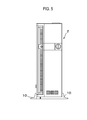
- FIG. 5 is a view showing an exemplary use of the stand in an information processing apparatus having a relatively-large width.
- FIG. 6 is a view showing an exemplary use of the stand in the information processing apparatus having a relatively-large width.
- FIG. 7 is a view showing an exemplary use of the stand in the information processing apparatus having a relatively-large width.
- FIG. 8 is a view showing the stand of the first embodiment having an elastic member.
- FIG. 9 is a front view showing an assembly of two stands of the first embodiment.
- FIG. 10 is a perspective bottom view showing the stand having an elastic member.
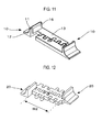
- FIG. 11 is a perspective view showing a stand for an information processing apparatus according to a second embodiment.
- FIG. 12 is a view showing the stand of the second embodiment in which a distance between supporting members is shortened.
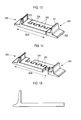
- FIG. 13 is a perspective view showing a stand for an information processing apparatus according to a third embodiment.
- FIG. 14 is a view showing the stand of the third embodiment in which a distance between supporting members is widened.
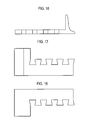
- FIG. 15 is a front view showing the stand of the third embodiment.
- FIG. 16 is a rear view showing the stand of the third embodiment.
- FIG. 17 is a plan view showing the stand of the third embodiment.
- FIG. 18 is a bottom view showing the stand of the third embodiment.
- FIG. 19 is a right side view showing the stand of the third embodiment.
- FIG. 20 is a left side view showing the stand of the third embodiment.
- FIG. 21 is a view showing an application example of the stand of the third embodiment.
- FIG. 22 is a view showing an application example of the stand of the third embodiment.
- a stand for an information processing apparatus includes a supporting member supporting the information processing apparatus from a side thereof, and a coupling member having protrusions and recesses on a first side thereof, which are spaced at a certain interval and have shapes engageable with each other.
- the stand also includes a protruding member provided on an end of the coupling member and protruded from the supporting member in a direction opposite to the coupling member.
- the information processing apparatus includes personal computers (PCs) and point-of-sale (POS) terminals.
- PCs personal computers
- POS point-of-sale
- FIG. 1 is a perspective bottom view of a stand 10 for an information processing apparatus according to the first embodiment.
- a portion A of FIG. 1 illustrates a perspective view as seen from the bottom side
- a portion B of FIG. 1 is a perspective view as seen from the front side.
- respective stands 10 include a supporting member 11 for supporting an information processing apparatus from the side section, a protruding member 12 for preventing the information processing apparatus from turning over, and a coupling member 13 for coupling two stands 10 with each other.
- the supporting member 11 is formed between the coupling member 13 and the protruding member 12, and has a plate shape that extends upwards from a bottom side thereof.
- the protruding member 12 is provided on one end of the coupling member 13 and has a plane part that is parallel with a surface on which the stand 10 is installed.
- the protruding member 12 is provided on one end of the coupling member 13 and protruded from the supporting member 11 in a direction opposite to the coupling member 13.
- the coupling member 13 has a plurality of protrusions 14 and recesses 15, which are spaced at regular intervals, respectively.
- the protrusions 14 and recesses 15 have shapes engageable with each other.
- the two protrusions 14 are provided on a part of the coupling member 13 on the side of the protruding member 12, while the two recesses 15 are provided on the other part of the coupling member 13.
- the protrusion 14 has an engaging part, a width of which is wider than that of a root portion of the protrusion 14 coupled to the coupling member 13.
- the engaging part prevents the protrusion 14 from being easily disengaged from the recess 15 even when a force is applied thereto from the transverse direction.
- the protrusions 14 and the recesses 15 are provided on one side of the coupling member 13. Two stands are coupled by placing the protrusions 14 and the recesses 15 of one stand exactly above the corresponding recesses and protrusions of the other stand. Subsequently, the two stands are vertically moved towards each other so as to engage the protrusions 14 of one stand with the recesses 15 of the other stand.
- FIGS. 2 to 4 are views showing an exemplary use of the stand in an information processing apparatus having a relatively-small width.
- FIGS. 2 to 4 illustrate a front view, a perspective view, and a perspective bottom view of the stand used in the information processing apparatus, respectively.
- a set of two stands 10 are engaged with each other.
- a pair of stands are used for a single information processing apparatus 1.
- the information processing apparatus 1 is installed between a pair of the supporting members 11 to place the apparatus on the stands 10.
- the number of protrusions 14 and recesses 15 in the two stands 10, which are engaged with each other is increased.
- a total of four pairs of protrusions 14 and recesses 15 are engaged with each other.
- FIGS. 5 to 7 are views showing an exemplary use of the stand in an information processing apparatus having a relatively-large width.
- FIGS. 5 to 7 illustrate a front view, a perspective view, and a perspective bottom view of the stand used in the information processing apparatus, respectively.
- the number of protrusions 14 and recesses 15 in the two stands 10, which are engaged with each other is reduced.
- a total of two pairs of protrusions 14 and recesses 15 are engaged with each other.
- FIG. 8 is a perspective view showing the stand 10 having an elastic member 16.
- the stand 10 includes the elastic member 16 on one side of the supporting members 11 facing the coupling member 13, i.e. on the side of the supporting member 11 facing an information processing apparatus 3.
- the elastic member 16 is an elastic body such as rubber, elastic resin, springs or the like.
- FIG. 9 is a front view showing an assembly of two stands 10. As shown in FIG. 9 , only one of the two stands 10 is provided with the elastic member 16.
- FIG. 10 is a perspective bottom view showing an exemplary use of the stand 10 having the elastic member 16. As shown in FIG. 10 , to fill a gap formed between the supporting member 11 and the information processing apparatus 3 when the two stands 10 are coupled to each other, the elastic member 16 is installed onto one or both of the two stands 10.
- the thickness of the elastic member 16 is equal to or larger than the thickness obtained by subtracting a width of the information processing apparatus 3 from a distance between the respective supporting members 11 of the two stands 10.
- the stand 10 for an information processing apparatus includes the supporting member 11 that supports the information processing apparatus from the side section, the protruding member 12 that prevents the apparatus from turning over, and the coupling member 13 having the protrusions 14 and the recesses 15, which are spaced at a certain interval and have shapes engageable with each other.
- the stand 10 can be provided to be applicable to various information processing apparatuses having different thicknesses, at low cost, using a single die.
- FIG. 11 is a perspective view showing a stand 20 for an information processing apparatus according to the second embodiment.
- the respective stands 20 include a supporting member 21 that supports the information processing apparatus from the side section, a protruding member 22 that prevents the information processing apparatus from turning over, and a coupling member 23 that couples two stands 20 with each other.
- the supporting member 21 is located between the coupling member 23 and the protruding member 22, and has a plate shape that extends upwards.
- the protruding member 22 is provided on one end of the coupling member 23 and has a plane part that is parallel with a surface on which the stand 20 is installed.
- the protruding member 22 is provided on one end of the coupling member 23 and protrudes from the supporting member 21 in a direction opposite to the supporting member 21.
- the coupling member 23 has on a first side face thereof a plurality of protrusions 24 and recesses 25, which are spaced at a certain interval, respectively.
- the protrusions 24 and recesses 25 have shapes engageable with each other.
- the coupling member 23 has, on a second side face thereof opposite to the first side face, a plurality of protrusions 26 and recesses 27, which are spaced at a certain interval, respectively.
- the interval between the protrusions 26 (or the recesses 27) on the second side face is arranged to be different from the interval between the protrusions (or the recesses) on the first side face.
- the protrusions 26 and recesses 27 have shapes engageable with each other.
- the two protrusions 24 are arranged on a part of the coupling member 23 on the side of the protruding member 22, while the two recesses 25 are arranged on the other part of the coupling member 23.
- the four recesses 27 are arranged on a part of the coupling member 23 on the side of the protruding member 22, while the two protrusions 26 are provided on the other part of the coupling member 23.
- Each of the protrusions 24 and 26 has an engaging part, a width of which is wider than that of a root portion of the protrusion 24 coupled to the coupling member 23.
- the engaging parts prevent the protrusions 24 and 26 from being easily disengaged from the recesses 25 and 27 even when a force is applied thereto in the transverse direction.
- the protrusions 24 and the recesses 25 are provided on the first side face of the coupling member 23. Accordingly, if the first side face of the first stand 20 is aligned to face the first side face of the second stand 20, then the protrusions 24 of one stand 20 are also aligned to face the recesses 25 of the other stand 20. Then, the two stands 20 are vertically moved towards each other so as to engage the protrusions 24 with the recesses 25.
- the two stands 20 are coupled to each other by engaging the protrusions 24 with the recesses 25, the space formed by the stands 20 does not fit with the width of the information processing apparatus to be installed.
- the protrusions 26 and the recesses 27 are arranged to engage them with each other.
- the protrusions 26 and the recesses 27 are provided on the second side face of the coupling member 23.
- the protrusions 26 of one stand 20 are also aligned to face the recesses 27 of the other stand 20. Then, the two stands 20 are vertically moved towards each other so as to engage the protrusions 26 with the recesses 27.
- the protrusions 26 and the recesses 27 of the two stands 20 are engaged so as to have a large distance between a pair of the supporting members 21 .
- the distance between the supporting members 21 is indicated as W1.
- FIG. 12 is a view of the two stands coupled to each other, where the distance between supporting members 21 is shortened compared to the embodiment shown in FIG. 11 .
- W2 the distance between the supporting members 21 is indicated as W2, which is smaller than W1.
- the stand 20 for an information processing apparatus includes the supporting member 21 that supports the information processing apparatus from the side section, the protruding member 22 that prevents the information processing apparatus from turning over, and the coupling member 23.
- the coupling member 23 has on the first side face thereof the plurality of protrusions 24 and recesses 25, which are spaced at a certain interval, respectively.
- the protrusions 24 and recesses 25 have shapes engageable with each other.
- the coupling member 23 has, on the second side face opposite to the first side face, the plurality of protrusions 26 and recesses 27, which are spaced at a certain interval, respectively.
- the interval between the protrusions 26 (or the recesses 27) is arranged to be different from the interval between the protrusions (or the recesses) on the first side face. Also, the protrusions 26 and recesses 27 have shapes engageable with each other.
- the stand 20 can be provided to be applicable to various information processing apparatuses having different thicknesses, at low cost, using a single die.
- FIG. 13 is a perspective view showing a stand 30 for an information processing apparatus according to the embodiment.
- the stand 30 includes a supporting member 31 that supports the information processing apparatus from the side section, a protruding member 32 that prevents the information processing apparatus from turning over, and a coupling member 33 that couples two stands 30 with each other.
- the supporting member 31 is located between the coupling member 33 and the protruding member 32, and has a plate shape that extends upwards.
- the protruding member 32 is provided on one end of the coupling member 33 and has a plane part that is parallel with a surface on which the stand 30 is installed.
- the protruding member 32 is provided on one end of the coupling member 33 and protrudes in a direction opposite to the supporting member 31.
- the coupling member 33 has on a side face thereof a plurality of protrusions 34 and recesses 35, which are alternately placed at a certain interval.
- the protrusions 34 and recesses 35 have shapes engageable with each other.
- the four protrusions 34 and four recesses 35 are alternately provided on one side face of the coupling member 33.
- Each of the protrusions 34 has an engaging part, a width of which is wider than that of a root portion of the protrusion 34 coupled to the coupling member 33.
- the engaging parts prevent the protrusions 34 from being easily disengaged from the recesses 35 even when a force is applied thereto in the transverse direction.
- the protrusions 34 and the recesses 35 are provided on one side face of the coupling member 33. Accordingly, the side face of the first stand 30 is aligned to face with the side face of the second stand 30. Then, the two stands are vertically moved towards each other so as to engage the protrusions 34 with the recesses 35.
- the protrusions 34 are engaged with the recesses 35 so as to couple the two stands 30 to each other with a short distance between the pair of supporting members 31. That is, the two stands 30 are coupled to each other by engaging a larger number of the protrusions 34 with the corresponding recesses 35.
- a total of eight pairs of protrusions 34 and recesses 35 are engaged with each other.
- the distance between the supporting members 31 is indicated as W3.
- FIG. 14 is a perspective view of the two stands coupled to each other, where the distance between supporting members 31 is shortened compared to the embodiment of FIG. 13 .
- two stands 30 are coupled to each other by engaging a smaller number of the protrusions 34 with the corresponding recesses 35.
- a total of six pairs of protrusions 34 and recesses 35 are engaged with each other.
- W4 the distance between the supporting members 31 is indicated as W4, which is wider than W3.
- FIGS. 15 to 18 illustrate a front view, a rear view, a plan view, and a bottom view of the stand 30, respectively. Further, FIG.S. 19 and 20 illustrate a right side view and a left side view of the stand 30, respectively.
- the stand 30 for an information processing apparatus is employed to prevent an information processing apparatus, such as personal computers (PCs), point-of-sale (POS) terminals, or the like, from being turned over.
- One set of the stands include a pair of stands, such that the two stands are coupled to each other by engaging the protrusions 34 with the corresponding recesses 35.
- two sets of stands are employed to support an information processing apparatus between the supporting members 31 of respective stands.
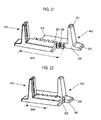
- FIGS. 21 and 22 are perspective views of a stand 40 according to an alternate example of the embodiment.
- the stand 40 includes a protruding member 32 which has a notch portion 36.
- the notch portion 36 is coupled to a recess 35 arranged at a position nearest to the supporting member 31, i.e. the recess 35 that is closest to the supporting member 31.
- the notch portion 36 is notched to a depth that is equal to or larger than the depth of the recess 35.
- two stands 40 are coupled by engaging the recesses 35 with the protrusions 34 so as to have a large distance between the pair of supporting members 31.
- the distance between the supporting members 31 is indicated as W5.
- two stands 40 are coupled by engaging the recesses 35 with the protrusions 34 so as to have a short distance between the pair of supporting members 31.
- the distance between the supporting members 31 is indicated as W6, which is smaller than W5.
- the protruding member 32 since the protruding member 32 has the notch portion 36, the protrusions 34 and the recesses 35 of two stands are engaged with each other so that the coupling member 33 of one stand can protrude out of the protruding member 32 of the other stand. Accordingly, the present embodiment is applicable to an information processing apparatus that has a smaller width.
- the stands 30 and 40 of the present embodiment include the supporting member 31 that supports the information processing apparatus from the side section, the protruding member 32 that prevents the information processing apparatus from turning over, and the coupling member 33 that has the protrusions 34 and the recesses 35 which are alternately arranged so as to be spaced at a certain interval and have shapes engageable with each other.
- the stands 30 and 40 are able to be used with various information processing apparatuses having different thicknesses, at low cost, using a single die.
Landscapes
- Engineering & Computer Science (AREA)
- Theoretical Computer Science (AREA)
- Microelectronics & Electronic Packaging (AREA)
- Computer Hardware Design (AREA)
- Power Engineering (AREA)
- Human Computer Interaction (AREA)
- Physics & Mathematics (AREA)
- General Engineering & Computer Science (AREA)
- General Physics & Mathematics (AREA)
- Casings For Electric Apparatus (AREA)
Applications Claiming Priority (1)
| Application Number | Priority Date | Filing Date | Title |
|---|---|---|---|
| JP2010040188A JP2011175539A (ja) | 2010-02-25 | 2010-02-25 | 情報処理装置スタンド |
Publications (2)
| Publication Number | Publication Date |
|---|---|
| EP2367409A2 true EP2367409A2 (de) | 2011-09-21 |
| EP2367409A3 EP2367409A3 (de) | 2012-05-09 |
Family
ID=44275903
Family Applications (1)
| Application Number | Title | Priority Date | Filing Date |
|---|---|---|---|
| EP10189930A Withdrawn EP2367409A3 (de) | 2010-02-25 | 2010-11-04 | Ständer für eine Informationsverarbeitungsvorrichtung |
Country Status (3)
| Country | Link |
|---|---|
| US (1) | US20110204199A1 (de) |
| EP (1) | EP2367409A3 (de) |
| JP (1) | JP2011175539A (de) |
Families Citing this family (3)
| Publication number | Priority date | Publication date | Assignee | Title |
|---|---|---|---|---|
| JP5017465B1 (ja) | 2011-02-21 | 2012-09-05 | 株式会社東芝 | 電子機器、スタンド |
| US8800786B2 (en) * | 2011-12-13 | 2014-08-12 | Howard Parkins | Portable bicycle stand |
| JP6524466B2 (ja) * | 2015-02-27 | 2019-06-05 | Re・Leaf株式会社 | 電子機器用スタンド |
Family Cites Families (12)
| Publication number | Priority date | Publication date | Assignee | Title |
|---|---|---|---|---|
| JPH0531012A (ja) * | 1991-07-31 | 1993-02-09 | Karl Jimuki Kk | ブツクエンド |
| US5183163A (en) * | 1992-01-30 | 1993-02-02 | Slaiken Stephen J | Interlocking-continuous base bookends |
| JPH06115A (ja) * | 1992-06-18 | 1994-01-11 | Karl Jimuki Kk | ブックエンド |
| JPH06350276A (ja) * | 1993-06-14 | 1994-12-22 | Hitachi Ltd | 縦置き姿勢支持具 |
| JPH0949212A (ja) * | 1995-08-09 | 1997-02-18 | Hitachi Building Syst Co Ltd | 視覚障害者用通行シート |
| TW468807U (en) * | 1999-11-05 | 2001-12-11 | Hon Hai Prec Ind Co Ltd | Fixed stand for the computer host |
| US6352162B1 (en) * | 2000-07-27 | 2002-03-05 | Block And Company, Inc. | Interlocking bookends |
| JP4195806B2 (ja) * | 2002-09-30 | 2008-12-17 | 富士通株式会社 | 複数筐体設置用スタンド |
| JP2004321432A (ja) * | 2003-04-24 | 2004-11-18 | Ippo:Kk | 敷物部材 |
| TWM242989U (en) * | 2003-10-07 | 2004-09-01 | Tatung Co | Feet stand structure |
| JP3134799U (ja) * | 2007-06-13 | 2007-08-23 | 株式会社Njテクノ | 一体化装置 |
| TWM344014U (en) * | 2008-04-02 | 2008-11-01 | Wistron Corp | Assembly supporting apparatus |
-
2010
- 2010-02-25 JP JP2010040188A patent/JP2011175539A/ja active Pending
- 2010-11-02 US US12/917,716 patent/US20110204199A1/en not_active Abandoned
- 2010-11-04 EP EP10189930A patent/EP2367409A3/de not_active Withdrawn
Non-Patent Citations (1)
| Title |
|---|
| None |
Also Published As
| Publication number | Publication date |
|---|---|
| JP2011175539A (ja) | 2011-09-08 |
| US20110204199A1 (en) | 2011-08-25 |
| EP2367409A3 (de) | 2012-05-09 |
Similar Documents
| Publication | Publication Date | Title |
|---|---|---|
| US8184442B2 (en) | Case of an electronic device | |
| US9478883B2 (en) | Card connector | |
| KR20140113327A (ko) | 커넥터 | |
| JP2013118239A5 (ja) | 筐体のフレームおよびフレーム連結部材 | |
| US20160133889A1 (en) | Battery holder | |
| US20110204199A1 (en) | Stand for information processing apparatus | |
| US9736954B2 (en) | Retaining device for power distribution unit | |
| TWI555462B (zh) | The quick release structure of the servo slide and the cable management frame | |
| US8453985B2 (en) | Mounting device for fixing peripheral device to server | |
| KR200469373Y1 (ko) | 전기 커넥터 | |
| US20150048726A1 (en) | Mounting apparatus for bracket | |
| US9449586B2 (en) | Keyboard device | |
| US8373981B2 (en) | Expansion card fastening device | |
| US20130102193A1 (en) | Shielding shell of a connector | |
| US20150048040A1 (en) | Cabinet structure | |
| US20120146469A1 (en) | Computer case | |
| CN104275608B (zh) | 夹具定位板 | |
| CN202282910U (zh) | 电路板固定结构 | |
| CN204577295U (zh) | 滑动键和电子装置 | |
| CN111683516B (zh) | 一种可快速拆卸的弹簧夹结构和承载盘 | |
| CN103166288A (zh) | Ups机箱底座 | |
| CN203009497U (zh) | 橱柜的连接器 | |
| US20110273853A1 (en) | Computer system with riser card | |
| CN202172175U (zh) | 电子卡连接器、耳扣、电路板及电子设备 | |
| CN116408762B (zh) | 一种堆叠工具箱 |
Legal Events
| Date | Code | Title | Description |
|---|---|---|---|
| PUAI | Public reference made under article 153(3) epc to a published international application that has entered the european phase |
Free format text: ORIGINAL CODE: 0009012 |
|
| 17P | Request for examination filed |
Effective date: 20101104 |
|
| AK | Designated contracting states |
Kind code of ref document: A2 Designated state(s): AL AT BE BG CH CY CZ DE DK EE ES FI FR GB GR HR HU IE IS IT LI LT LU LV MC MK MT NL NO PL PT RO RS SE SI SK SM TR |
|
| AX | Request for extension of the european patent |
Extension state: BA ME |
|
| PUAL | Search report despatched |
Free format text: ORIGINAL CODE: 0009013 |
|
| AK | Designated contracting states |
Kind code of ref document: A3 Designated state(s): AL AT BE BG CH CY CZ DE DK EE ES FI FR GB GR HR HU IE IS IT LI LT LU LV MC MK MT NL NO PL PT RO RS SE SI SK SM TR |
|
| AX | Request for extension of the european patent |
Extension state: BA ME |
|
| RIC1 | Information provided on ipc code assigned before grant |
Ipc: F16M 11/00 20060101ALI20120330BHEP Ipc: G06F 1/18 20060101ALI20120330BHEP Ipc: G06F 1/16 20060101ALI20120330BHEP Ipc: H05K 5/02 20060101AFI20120330BHEP |
|
| STAA | Information on the status of an ep patent application or granted ep patent |
Free format text: STATUS: THE APPLICATION HAS BEEN WITHDRAWN |
|
| 18W | Application withdrawn |
Effective date: 20120904 |