EP2367723B1 - Kraftwerkzeug für metallverriegelungsbinder aus rostfreiem stahl - Google Patents
Kraftwerkzeug für metallverriegelungsbinder aus rostfreiem stahl Download PDFInfo
- Publication number
- EP2367723B1 EP2367723B1 EP09764644.2A EP09764644A EP2367723B1 EP 2367723 B1 EP2367723 B1 EP 2367723B1 EP 09764644 A EP09764644 A EP 09764644A EP 2367723 B1 EP2367723 B1 EP 2367723B1
- Authority
- EP
- European Patent Office
- Prior art keywords
- tool
- gear carrier
- tie
- toggle
- lever arm
- Prior art date
- Legal status (The legal status is an assumption and is not a legal conclusion. Google has not performed a legal analysis and makes no representation as to the accuracy of the status listed.)
- Active
Links
Images







Classifications
-
- B—PERFORMING OPERATIONS; TRANSPORTING
- B25—HAND TOOLS; PORTABLE POWER-DRIVEN TOOLS; MANIPULATORS
- B25B—TOOLS OR BENCH DEVICES NOT OTHERWISE PROVIDED FOR, FOR FASTENING, CONNECTING, DISENGAGING OR HOLDING
- B25B25/00—Implements for fastening, connecting or tensioning of wire or strip
-
- B—PERFORMING OPERATIONS; TRANSPORTING
- B65—CONVEYING; PACKING; STORING; HANDLING THIN OR FILAMENTARY MATERIAL
- B65B—MACHINES, APPARATUS OR DEVICES FOR, OR METHODS OF, PACKAGING ARTICLES OR MATERIALS; UNPACKING
- B65B13/00—Bundling articles
- B65B13/18—Details of, or auxiliary devices used in, bundling machines or bundling tools
- B65B13/185—Details of tools
-
- B—PERFORMING OPERATIONS; TRANSPORTING
- B65—CONVEYING; PACKING; STORING; HANDLING THIN OR FILAMENTARY MATERIAL
- B65B—MACHINES, APPARATUS OR DEVICES FOR, OR METHODS OF, PACKAGING ARTICLES OR MATERIALS; UNPACKING
- B65B13/00—Bundling articles
- B65B13/02—Applying and securing binding material around articles or groups of articles, e.g. using strings, wires, strips, bands or tapes
- B65B13/025—Hand-held tools
- B65B13/027—Hand-held tools for applying straps having preformed connecting means, e.g. cable ties
-
- B—PERFORMING OPERATIONS; TRANSPORTING
- B65—CONVEYING; PACKING; STORING; HANDLING THIN OR FILAMENTARY MATERIAL
- B65B—MACHINES, APPARATUS OR DEVICES FOR, OR METHODS OF, PACKAGING ARTICLES OR MATERIALS; UNPACKING
- B65B13/00—Bundling articles
- B65B13/02—Applying and securing binding material around articles or groups of articles, e.g. using strings, wires, strips, bands or tapes
Definitions
- the present invention relates to a power tool for stainless steel metal locking ties, and more particularly to a power tool for stainless steel metal locking ties having a power source to tension the locking tie and to cut the locking tie.
- US 4 371 010 discloses such a tool according to the preamble of claim 1.
- Cable ties or straps are used to bundle or secure a group of articles such as electrical wires and cables.
- Cable ties of conventional construction include a cable tie head and an elongated tail extending therefrom. The tail is wrapped around a bundle of articles and thereafter inserted through the passage in the head.
- the head of the cable tie typically supports a locking element, which extends into the head passage and engages the body of the tail to secure the tail to the head.
- the present invention is directed towards a power tool for installing a metal locking tie.
- the tool includes a body and a power chassis.
- a gear carrier is positioned in the body and a tensioning mechanism is mounted in the gear carrier.
- a cutting mechanism is also positioned in the tool body and positioned to engage the gear carrier. As the tie is tensioned, the gear carrier moves linearly in the tool body to cut the tensioned tie.
- FIG. 1 is a front left side perspective view of the power tool for stainless steel metal locking ties of the present invention
- FIG. 2 is a front left side perspective view of the power tool for stainless steel metal locking ties of FIG. 1 with the tool in a rotated position;
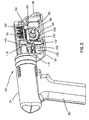
- FIG. 3 is a right side perspective view of the power tool of FIG. 1 with a portion of the tool removed;
- FIG. 4 is a right side view of the power tool of FIG. 3 ;
- FIG. 5 is a front perspective view of the gear carrier in the power tool of FIG. 3 ;
- FIG. 6 is a right side perspective view of the worm mounted to the gear carrier in the power tool of FIG. 3 ;
- FIG. 7 is a side perspective view of the toggle mechanism of FIG. 4 ;
- FIG. 8 is a partial right side perspective view of the tool body of FIG. 1 ;
- FIG. 9a is a top view of the gear carrier and the toggle mechanism of FIG. 3 ;
- FIG. 9b is a side view of the gear carrier and the toggle mechanism of FIG. 9a ;
- FIG. 10 is a side view of the gear carrier and the toggle mechanism of FIG. 9a with the mandrel beginning to wind the stainless steel tie;
- FIG. 11 is a side view of the gear carrier and the toggle mechanism of FIG. 9a with the detent setting of the toggle mechanism being overcome;
- FIG. 12 is a side view of the gear carrier and the toggle mechanism of FIG. 9a with the tie being tensioned and the gear carrier moving forward to cut the stainless steel metal locking tie;
- FIG. 13 is a side view of the gear carrier and the toggle mechanism of FIG. 9a returned to the starting position after the tie has been cut.
- FIG. 1 illustrates the portable power tool 20 for stainless steel metal locking ties 220 of the present invention.
- the power tool 20 includes an adjustable tension setting and an automatic cut-off mechanism operated by the same power source.
- the tool 20 has a tool body 30 with a nose 32 at the front of the tool body 30, a power chassis 34 for housing a battery and a handle 36.
- the tool body 30 is attached to the power chassis 34 by a swivel connector 38.
- the swivel connector 38 enables the tool body 30 and the power chassis 34 to be rotated with respect to one another for ease of use. As a result, the operator may rotate the tool body 30 to position the tool at different angles to install the stainless steel locking ties.
- the tool body 30 also includes a worm 52, a worm gear 54, a worm gear shaft 56 and a mandrel 58 for tensioning the stainless steel locking tie 220 (see FIGS. 9a-13 ).
- the tool nose 32 includes a cutting mechanism 200 for cutting the stainless steel locking tie 220 (see FIGS. 9b-13 ).
- the tool 20 includes a gear carrier 50 which moves linearly in the tool body 30 along a carrier guide 51 toward the nose 32 of the tool 20.
- the worm 52 is mounted on the worm shaft 53 (see FIG. 6 ).
- the worm shaft 53 is mounted in the tool body 30 and ends in a hexagonal driver which fits into the output shaft of the power chassis 34 (not shown).
- the worm gear 54, worm gear shaft 56 and mandrel 58 are mounted in the gear carrier 50 and positioned such that the worm 52 engages the worm gear 54.
- the mandrel 58 is part of the worm gear shaft 56.
- the gear carrier 50 with the worm gear 54 and worm gear shaft 56 are housed in the tool body 30 while the mandrel 58 extends from the tool body 30.
- the gear carrier 50 can move linearly toward the front of the tool, but is held in place in the tool body 30 by a spring loaded toggle mechanism 100 (see FIG. 7 ).
- the toggle mechanism 100 includes a toggle link 102 with a torsion spring 114 (see FIGS. 3 and 4 ) and a lever arm 120 with a lever arm pivot 126.
- the lever arm pivot 126 is fixed in the stationary plate 140.
- the lever arm 120 is generally L-shaped with a horizontally extending portion 122 and a generally vertically extending portion 128.
- the lever arm pivot 126 is located at the intersection of the horizontally extending portion 122 and the vertically extending portion 128.
- the vertically extending portion 128 includes a detent pocket 130.
- the toggle link 102 is located at an end of the gear carrier 50 opposite the worm gear 54, worm gear shaft 56 and mandrel 58.
- the toggle link 102 includes a first end 104 and a second end 106.
- the first end 104 of the toggle link 102 pivots about a rod 108 that is mounted to the gear carrier 50.
- a torsion spring 114 is positioned on the rod 108.
- the second end 106 of the toggle link 102 has two rollers 110 which are free to rotate on pin 112. Both of the rollers 110 rest on a stationary plate 140 that is generally vertically orientated and attached to the tool body 30.
- a portion of pin 112 rests in the detent pocket 130 in the vertically extending portion 128 of the lever arm 120.
- the torsion spring 114 presses both rollers 110 against the stationary plate 140 which provides a force reduction on the pin 112 in the detent pocket 130.
- the toggle link 102 is limited to a minimum rotational angle of no more than six degrees with respect to the linear movement of the gear carrier 50. By limiting the angle of the toggle link 102 to no more than six degrees, or nearly in-line, with the line of force exerted by the stainless steel locking tie 220, the force is reduced and only a small component of that force is resisted by the pin 112 in detent pocket 130.
- the tool body 30 also houses a spring loaded plate 150 and an actuator pin 154 for adjusting the tension setting.
- the actuator pin 154 is guided linearly in a slot in the tool body 30 and can be moved manually to adjust the detent force.
- the spring loaded plate 150 includes springs 152 that force the plate 150 to counteract the rotational force exerted by the toggle link 102 on the lever arm 120.
- the tension setting can be adjusted by moving the actuator pin 154 ( FIG. 4 ) linearly along the load plate 150 thereby varying the moment arm between the lever arm pivot 126 and the point the load plate force is applied.
- the horizontally extending portion of the lever arm may also include a pocket 124 (see FIG. 7 ). The pocket 124 houses the actuator pin when it is desirable to remove the spring load from the lever arm 120.
- FIGS. 9-13 illustrate the operation of the power tool of the present invention.
- FIGS. 9a and 9b illustrate the gear carrier 50 and the toggle mechanism 100 in a starting position before the tool 20 begins to tension the stainless steel tie 220.
- the worm 52 engages the worm gear 54 thereby rotating the worm gear 54, worm gear shaft 56 and mandrel 58.
- the stainless steel tie 220 has been inserted and wound on the mandrel 58.
- the gear carrier 50 is held in place by the toggle mechanism 100.
- the gear carrier 50 moves linearly toward the front of the tool as the tie 220 is tensioned around the mandrel 58 and the toggle mechanism 100 detents.
- the torsion spring 114 presses the toggle link rollers 110 against the generally vertically orientated stationary plate 140.
- the orientation of the stationary plate 140 provides a force reduction on the toggle mechanism detent.
- the pin 112 of the toggle link 102 is positioned in the detent pocket 130 of the vertical portion 128 of the lever arm 120.
- the gear carrier 50 is positioned in a starting position located a distance A from the nose 32 of the tool 20.
- the worm 52 drives the worm gear 54 rotating the worm gear shaft 56 and mandrel 58.
- the mandrel 58 rotates, it winds the stainless steel tie 220 to tension the tie 220.
- a linear force is exerted on the gear carrier 50.
- FIG. 11 illustrates the mandrel 58 continuing to tension the tie 220.
- the linear force exerted on the gear carrier 50 begins to overcome the spring load on the toggle mechanism 100.
- the pin 112 on the end of the toggle link 102 forces the lever arm 120 to tilt as the pin 112 detents out of the detent pocket 130 in the vertical portion 128 of the lever arm 120.
- the gear carrier 50 is now positioned at a distance A-B from the nose 32 of the tool 20.
- the cutting mechanism 200 is actuated.
- the cutting mechanism 200 is located in the nose 32 of the tool 20. As illustrated in FIGS. 9b-13 , the cutting mechanism 200 includes a cutter 208, a cutter lever 204 and a roller 206. The cutter 208 and the roller 206 are positioned at opposite ends of the cutter lever 204.
- the front of the gear carrier 50 includes a ramp 202. The ramp 202 is designed to actuate the cutter 208 via the roller 206 at the opposite end of the cutter lever 204. As the gear carrier 50 is pulled forward, the roller 206 travels along the ramp 202 raising the cutter lever 204 to enable the cutter 208 to cut the tie 220.
- FIG. 12 illustrates the mandrel 58 further winding the stainless steel tie 220 and the gear carrier 50 pulled closer to the front of the tool 20 such that the gear carrier 50 is positioned at a distance A-C from the nose 32 of the tool 20.
- the worm gear 54 moves linearly along the worm 50.
- the worm gear 54 continues to move along the worm 50 until the stainless steel tie 220 is completely cut.
- the tensioning force which pulled the gear carrier 50 forward is removed.
- the torsion spring 114 is now able to rotate the toggle link 102 back to the nearly horizontal position, exerting a linear force against the stationary plate 140 and moving the gear carrier 50 back to the starting position.
- the toggle link 102 rotates back to the starting position, the end of pin 112 falls back into the detent pocket 130.
- the gear carrier 50 moves back to the starting position, the worm gear 54 walks back along the worm 52.
- FIG. 13 illustrates the gear carrier 50 returned to the starting position where the gear carrier 50 is positioned at a distance A away from the nose 32 of the tool 20.
Landscapes
- Engineering & Computer Science (AREA)
- Mechanical Engineering (AREA)
- Basic Packing Technique (AREA)
Claims (9)
- Werkzeug (20) zum Anbringen eines Metallverschlussbands (220), wobei das Werkzeug aufweist:einen Werkzeugkörper (30);einen Getriebeträger (50), der in dem Werkzeugkörper (30) angeordnet ist;einen Spannmechanismus (52, 54, 56, 58), der in dem Getriebeträger (50) angebracht ist; undeinen Schneidmechanismus (206), der mit dem Getriebeträger (50) in Eingriff steht,dadurch gekennzeichnet, dasssich der Getriebeträger (50) in dem Werkzeugkörper (30) linear bewegt, sobald das Band (220) gespannt ist, um das Band (220) zu schneiden.
- Werkzeug nach Anspruch 1, das des Weiteren einen Kniehebelmechanismus (100) aufweist, der in dem Werkzeugkörper (30) angeordnet ist, wobei der Kniehebelmechanismus (100) den Getriebeträger (50) an Ort und Stelle hält, bis eine Kipphaltekraft überschritten worden ist.
- Werkzeug nach Anspruch 2, wobei die Kipphaltekraft federbeaufschlagt ist.
- Werkzeug nach Anspruch 1, das des Weiteren einen Kniehebelmechanismus (100) aufweist, der eine Gelenkstange (102) und einen Hebelarm (120) aufweist, wobei die Gelenkstange (102) mit dem Hebelarm (120) in Eingriff steht.
- Werkzeug nach Anspruch 4, wobei der Hebelarm (120) einen sich horizontal erstreckenden Abschnitt (122), ein Hebelarmgelenk (126) und einen sich vertikal erstreckenden Abschnitt (128) aufweist, wobei der sich vertikal erstreckende Abschnitt (128) eine Arretierung (130) zur Aufnahme der Gelenkstange (102) aufweist.
- Werkzeug nach Anspruch 4, wobei die Gelenkstange (102) eine Torsionsfeder (114) aufweist.
- Werkzeug nach Anspruch 1, wobei der Schneidmechanismus (200) einen Schneidhebel (204) mit einer Rolle (206) und einem Schneideelement (208) aufweist, wobei die Rolle (206) mit dem Getriebeträger (40) in Eingriff steht, um das Schneideelement (208) zu betätigen.
- Werkzeug nach Anspruch 1, wobei der Spannmechanismus (52, 54, 56, 58) eine Schnecke (52) aufweist, die ein Schneckengetriebe (54) betätigt, um einen Dorn (58) zu drehen.
- Werkzeug nach Anspruch 1, wobei der Körper (30) über eine Drehverbindung (38) an einem Antriebschassis (34) befestigt ist.
Applications Claiming Priority (2)
| Application Number | Priority Date | Filing Date | Title |
|---|---|---|---|
| US12/331,916 US20100139805A1 (en) | 2008-12-10 | 2008-12-10 | Power Tool for Stainless Steel Metal Locking Ties |
| PCT/US2009/065549 WO2010068408A2 (en) | 2008-12-10 | 2009-11-23 | Power tool for stainless steel metal locking ties |
Publications (2)
| Publication Number | Publication Date |
|---|---|
| EP2367723A2 EP2367723A2 (de) | 2011-09-28 |
| EP2367723B1 true EP2367723B1 (de) | 2013-05-15 |
Family
ID=42173965
Family Applications (1)
| Application Number | Title | Priority Date | Filing Date |
|---|---|---|---|
| EP09764644.2A Active EP2367723B1 (de) | 2008-12-10 | 2009-11-23 | Kraftwerkzeug für metallverriegelungsbinder aus rostfreiem stahl |
Country Status (8)
| Country | Link |
|---|---|
| US (2) | US20100139805A1 (de) |
| EP (1) | EP2367723B1 (de) |
| JP (1) | JP5436572B2 (de) |
| KR (1) | KR101530213B1 (de) |
| CN (1) | CN102256875B (de) |
| AU (1) | AU2009325000B2 (de) |
| TW (1) | TWI488717B (de) |
| WO (1) | WO2010068408A2 (de) |
Families Citing this family (25)
| Publication number | Priority date | Publication date | Assignee | Title |
|---|---|---|---|---|
| WO2010108050A2 (en) | 2009-03-19 | 2010-09-23 | Figure 8 Surgical, Inc. | Systems and methods for sternum repair |
| US8460295B2 (en) | 2009-03-19 | 2013-06-11 | Figure 8 Surgical, Inc. | Systems and methods for sternum repair |
| WO2011116379A2 (en) | 2010-03-19 | 2011-09-22 | Mcclelan William T | Knotless locking tissue fastening system and method |
| EP2616355A1 (de) * | 2010-09-14 | 2013-07-24 | Band-It-IDEX, Inc. | Bandklemmenschutz |
| WO2012174562A1 (en) | 2011-06-17 | 2012-12-20 | Figure 8 Surgical, Inc. | Sternum band tensioner device, system and method |
| US8561531B2 (en) * | 2011-08-31 | 2013-10-22 | Craig Joseph Rooth | Hand-held battery powered center punch band clamp tool |
| US9132928B2 (en) * | 2011-08-31 | 2015-09-15 | Craig J. Rooth | Hand-held battery powered center punch band clamp tool |
| US9272799B2 (en) | 2011-10-04 | 2016-03-01 | Signode Industrial Group Llc | Sealing tool for strap |
| WO2014008493A2 (en) | 2012-07-05 | 2014-01-09 | Golden Bear LLC | Externally-powered strapping tool and a strapping tool assembly utilized therein |
| US9468968B2 (en) * | 2012-08-30 | 2016-10-18 | Signode Industrial Group Llc | Battery powered tensioning tool for strap |
| US9630265B2 (en) | 2013-06-28 | 2017-04-25 | Signode Industrial Group Llc | Powered two-stage strap cutter |
| CN104150006B (zh) * | 2013-09-02 | 2016-09-14 | 许修义 | 一种手持式自动扎带工具 |
| US10577137B2 (en) | 2015-12-09 | 2020-03-03 | Signode Industrial Group Llc | Electrically powered combination hand-held notch-type strapping tool |
| CN106002814B (zh) * | 2016-07-11 | 2018-03-16 | 徐健民 | 一种扎带自动拉紧切割装置 |
| EP3272659B1 (de) * | 2016-07-21 | 2021-11-03 | TITAN Umreifungstechnik GmbH & Co.KG | Handumreifungs- und/oder verschlussgerät |
| US11066200B2 (en) * | 2017-11-27 | 2021-07-20 | Daniels Manufacturing Corporation | Apparatus for tensioning a cable lacing tape device |
| US11046466B2 (en) * | 2017-11-27 | 2021-06-29 | Daniels Manufacturing Corporation | Apparatus for tensioning a cable lacing tape device |
| CN107954082A (zh) * | 2017-12-14 | 2018-04-24 | 朱凌 | 一种多自由度手持扎带机内部结构 |
| US11352153B2 (en) | 2019-05-07 | 2022-06-07 | Signode Industrial Group Llc | Strapping tool |
| ES2966478T3 (es) * | 2019-08-30 | 2024-04-22 | Cordstrap B V | Método y dispositivo para tensar |
| EP4168312A2 (de) | 2020-07-13 | 2023-04-26 | Signode Industrial Group LLC | Bindewerkzeug |
| CN112460335A (zh) * | 2020-12-09 | 2021-03-09 | 艺达思科技(苏州)有限公司 | 管夹收紧装置 |
| US12420966B2 (en) | 2022-02-18 | 2025-09-23 | Signode Industrial Group Llc | Strapping tool with energy-release feature |
| WO2024010851A1 (en) * | 2022-07-06 | 2024-01-11 | Daniels Manufacturing Corporation | Apparatus for tensioning a cable lacing tape |
| KR102787330B1 (ko) | 2024-06-18 | 2025-03-31 | 동아베스텍 주식회사 | 케이블 타이 체결용 반자동 전동 공구 조립체 |
Family Cites Families (24)
| Publication number | Priority date | Publication date | Assignee | Title |
|---|---|---|---|---|
| US3661187A (en) * | 1969-07-28 | 1972-05-09 | Panduit Corp | Strap-tensioning and severing tool |
| US3891012A (en) * | 1973-10-23 | 1975-06-24 | Amp Inc | Apparatus for applying ties to bundles |
| NL80354C (de) * | 1976-05-25 | |||
| US4371010A (en) * | 1980-11-03 | 1983-02-01 | Thomas & Betts Corporation | Bundling tie applying tool |
| US4934416A (en) * | 1988-11-29 | 1990-06-19 | Joslyn Corporation | Power-operated banding tool |
| JPH03162218A (ja) * | 1989-11-15 | 1991-07-12 | Daiwa Kasei Kogyo Kk | ベルトクランプ用引締め装置 |
| US5167265A (en) * | 1991-07-05 | 1992-12-01 | Kyoichi Limited | Hand-operated binding device |
| US5163482A (en) * | 1991-09-27 | 1992-11-17 | Electro Adapter, Inc. | Tool for applying clamping bands |
| US5205328A (en) * | 1992-03-18 | 1993-04-27 | Panduit Corp. | Portable cable tie tool |
| DE9214900U1 (de) * | 1992-11-02 | 1994-03-03 | Paul Hellermann GmbH, 25421 Pinneberg | Bindewerkzeug |
| DE9214902U1 (de) * | 1992-11-02 | 1994-03-03 | Paul Hellermann GmbH, 25421 Pinneberg | Werkzeug zum Binden eines Gegenstands mittels eines Bandes |
| DE29617653U1 (de) * | 1996-10-10 | 1998-02-05 | Paul Hellermann GmbH, 25421 Pinneberg | Werkzeug zum Binden eines Kabelbaums |
| JP3803840B2 (ja) * | 1997-04-09 | 2006-08-02 | 千代田電子工業株式会社 | 結束用具 |
| EP1231158A1 (de) * | 2001-02-12 | 2002-08-14 | Hellermann Tyton GmbH | Magazinstreifen von Bandschlössern und Werkzeug für dessen Verarbeitung |
| US6481467B2 (en) * | 2001-03-15 | 2002-11-19 | Band-It-Idex, Inc. | Powered band clamping under electrical control |
| US7048015B2 (en) * | 2001-10-17 | 2006-05-23 | Challenger Manufacturing Consultants, Inc. | Powered clamp application tool |
| US6601616B1 (en) * | 2001-10-17 | 2003-08-05 | Challenger Manufacturing Consultants, Inc. | Powered clamp application tool |
| GB2409996B (en) | 2002-02-19 | 2005-10-12 | Spirent Plc | Banding tool |
| US20050111995A1 (en) * | 2003-11-25 | 2005-05-26 | Everson Rodney W. | Carbon dioxide power system and method |
| JP4586540B2 (ja) * | 2005-01-13 | 2010-11-24 | マックス株式会社 | 鉄筋結束機 |
| WO2007048109A1 (en) * | 2005-10-20 | 2007-04-26 | Panduit Corp. | Metal tie tool with rotary gripper and ball setting device |
| US7458398B2 (en) * | 2005-10-20 | 2008-12-02 | Panduit Corp. | Metal tie tool with rotary gripper and ball setting device |
| JP4224086B2 (ja) * | 2006-07-06 | 2009-02-12 | 三井金属鉱業株式会社 | 耐折性に優れた配線基板および半導体装置 |
| WO2008094078A2 (ru) | 2007-01-31 | 2008-08-07 | Burtsev Leonid Anatolievich | Устройство и способ питания усилителя низкой частоты |
-
2008
- 2008-12-10 US US12/331,916 patent/US20100139805A1/en not_active Abandoned
-
2009
- 2009-11-23 EP EP09764644.2A patent/EP2367723B1/de active Active
- 2009-11-23 WO PCT/US2009/065549 patent/WO2010068408A2/en not_active Ceased
- 2009-11-23 AU AU2009325000A patent/AU2009325000B2/en active Active
- 2009-11-23 KR KR1020117015269A patent/KR101530213B1/ko active Active
- 2009-11-23 JP JP2011540769A patent/JP5436572B2/ja active Active
- 2009-11-23 CN CN2009801529931A patent/CN102256875B/zh active Active
- 2009-12-01 TW TW098140983A patent/TWI488717B/zh active
-
2013
- 2013-07-15 US US13/941,609 patent/US8936049B2/en active Active
Also Published As
| Publication number | Publication date |
|---|---|
| EP2367723A2 (de) | 2011-09-28 |
| KR20110106331A (ko) | 2011-09-28 |
| TW201028256A (en) | 2010-08-01 |
| AU2009325000B2 (en) | 2014-11-20 |
| KR101530213B1 (ko) | 2015-06-19 |
| WO2010068408A2 (en) | 2010-06-17 |
| US20130327438A1 (en) | 2013-12-12 |
| JP5436572B2 (ja) | 2014-03-05 |
| WO2010068408A3 (en) | 2010-08-05 |
| CN102256875A (zh) | 2011-11-23 |
| TWI488717B (zh) | 2015-06-21 |
| US8936049B2 (en) | 2015-01-20 |
| US20100139805A1 (en) | 2010-06-10 |
| AU2009325000A1 (en) | 2011-06-30 |
| CN102256875B (zh) | 2013-09-04 |
| JP2012511483A (ja) | 2012-05-24 |
Similar Documents
| Publication | Publication Date | Title |
|---|---|---|
| EP2367723B1 (de) | Kraftwerkzeug für metallverriegelungsbinder aus rostfreiem stahl | |
| EP1948513B1 (de) | Metallzugwerkzeug mit drehgriff und kugelförmiger einstellungsvorrichtung | |
| EP2285692B1 (de) | Metallbindewerkzeug mit spannungsretention | |
| US7458398B2 (en) | Metal tie tool with rotary gripper and ball setting device | |
| US5921290A (en) | Handheld tensioning and cutoff tool | |
| EP1897809B1 (de) | Installationswerkzeug mit einem Klinkenrad | |
| EP1418124B1 (de) | Maschine zum binden von verstärkungsstahlstäben | |
| EP0558084B1 (de) | Verfahren und Vorrichtung zum Umschnüren von einem oder mehreren Gegenständen | |
| EP3052282B1 (de) | Schneidwerkzeug mit schnelllösender betätigter klingenführung | |
| US11008125B2 (en) | Tool for tensioning metal locking ties | |
| WO2010001345A2 (en) | Device for binding together at least one object, in particular a cable bunch, by a binding means | |
| JP7116082B2 (ja) | ワイヤ結束機内でワイヤを案内する装置および当該装置を含むワイヤ結束機 | |
| CN214722180U (zh) | 一种立柱配件折弯装置 | |
| CN216859107U (zh) | 一种断管设备远程进刀控制装置 | |
| US20090014702A1 (en) | Apparatus for dispensing and tensioning wire | |
| CN220445308U (zh) | 一种可移动焊丝送丝的简易工具 | |
| CN222927246U (zh) | 一种电缆线束辅助缠胶带装置 | |
| EP1350721A1 (de) | Kabelbinder-Installationswerkzeug | |
| JP7617699B2 (ja) | 結束装置 | |
| KR20140045796A (ko) | 밴드케이블 커팅기 | |
| HK40106599A (zh) | 捆束装置 | |
| JPH0517766B2 (de) |
Legal Events
| Date | Code | Title | Description |
|---|---|---|---|
| PUAI | Public reference made under article 153(3) epc to a published international application that has entered the european phase |
Free format text: ORIGINAL CODE: 0009012 |
|
| 17P | Request for examination filed |
Effective date: 20110621 |
|
| AK | Designated contracting states |
Kind code of ref document: A2 Designated state(s): AT BE BG CH CY CZ DE DK EE ES FI FR GB GR HR HU IE IS IT LI LT LU LV MC MK MT NL NO PL PT RO SE SI SK SM TR |
|
| DAX | Request for extension of the european patent (deleted) | ||
| GRAP | Despatch of communication of intention to grant a patent |
Free format text: ORIGINAL CODE: EPIDOSNIGR1 |
|
| GRAS | Grant fee paid |
Free format text: ORIGINAL CODE: EPIDOSNIGR3 |
|
| GRAA | (expected) grant |
Free format text: ORIGINAL CODE: 0009210 |
|
| AK | Designated contracting states |
Kind code of ref document: B1 Designated state(s): AT BE BG CH CY CZ DE DK EE ES FI FR GB GR HR HU IE IS IT LI LT LU LV MC MK MT NL NO PL PT RO SE SI SK SM TR |
|
| REG | Reference to a national code |
Ref country code: GB Ref legal event code: FG4D Ref country code: CH Ref legal event code: EP |
|
| REG | Reference to a national code |
Ref country code: AT Ref legal event code: REF Ref document number: 612017 Country of ref document: AT Kind code of ref document: T Effective date: 20130615 |
|
| REG | Reference to a national code |
Ref country code: IE Ref legal event code: FG4D |
|
| REG | Reference to a national code |
Ref country code: DE Ref legal event code: R096 Ref document number: 602009015747 Country of ref document: DE Effective date: 20130711 |
|
| REG | Reference to a national code |
Ref country code: AT Ref legal event code: MK05 Ref document number: 612017 Country of ref document: AT Kind code of ref document: T Effective date: 20130515 |
|
| REG | Reference to a national code |
Ref country code: LT Ref legal event code: MG4D |
|
| REG | Reference to a national code |
Ref country code: NL Ref legal event code: VDEP Effective date: 20130515 |
|
| PG25 | Lapsed in a contracting state [announced via postgrant information from national office to epo] |
Ref country code: NO Free format text: LAPSE BECAUSE OF FAILURE TO SUBMIT A TRANSLATION OF THE DESCRIPTION OR TO PAY THE FEE WITHIN THE PRESCRIBED TIME-LIMIT Effective date: 20130815 Ref country code: FI Free format text: LAPSE BECAUSE OF FAILURE TO SUBMIT A TRANSLATION OF THE DESCRIPTION OR TO PAY THE FEE WITHIN THE PRESCRIBED TIME-LIMIT Effective date: 20130515 Ref country code: GR Free format text: LAPSE BECAUSE OF FAILURE TO SUBMIT A TRANSLATION OF THE DESCRIPTION OR TO PAY THE FEE WITHIN THE PRESCRIBED TIME-LIMIT Effective date: 20130816 Ref country code: SE Free format text: LAPSE BECAUSE OF FAILURE TO SUBMIT A TRANSLATION OF THE DESCRIPTION OR TO PAY THE FEE WITHIN THE PRESCRIBED TIME-LIMIT Effective date: 20130515 Ref country code: PT Free format text: LAPSE BECAUSE OF FAILURE TO SUBMIT A TRANSLATION OF THE DESCRIPTION OR TO PAY THE FEE WITHIN THE PRESCRIBED TIME-LIMIT Effective date: 20130916 Ref country code: IS Free format text: LAPSE BECAUSE OF FAILURE TO SUBMIT A TRANSLATION OF THE DESCRIPTION OR TO PAY THE FEE WITHIN THE PRESCRIBED TIME-LIMIT Effective date: 20130915 Ref country code: LT Free format text: LAPSE BECAUSE OF FAILURE TO SUBMIT A TRANSLATION OF THE DESCRIPTION OR TO PAY THE FEE WITHIN THE PRESCRIBED TIME-LIMIT Effective date: 20130515 Ref country code: SI Free format text: LAPSE BECAUSE OF FAILURE TO SUBMIT A TRANSLATION OF THE DESCRIPTION OR TO PAY THE FEE WITHIN THE PRESCRIBED TIME-LIMIT Effective date: 20130515 Ref country code: AT Free format text: LAPSE BECAUSE OF FAILURE TO SUBMIT A TRANSLATION OF THE DESCRIPTION OR TO PAY THE FEE WITHIN THE PRESCRIBED TIME-LIMIT Effective date: 20130515 Ref country code: ES Free format text: LAPSE BECAUSE OF FAILURE TO SUBMIT A TRANSLATION OF THE DESCRIPTION OR TO PAY THE FEE WITHIN THE PRESCRIBED TIME-LIMIT Effective date: 20130826 |
|
| PG25 | Lapsed in a contracting state [announced via postgrant information from national office to epo] |
Ref country code: PL Free format text: LAPSE BECAUSE OF FAILURE TO SUBMIT A TRANSLATION OF THE DESCRIPTION OR TO PAY THE FEE WITHIN THE PRESCRIBED TIME-LIMIT Effective date: 20130515 Ref country code: BG Free format text: LAPSE BECAUSE OF FAILURE TO SUBMIT A TRANSLATION OF THE DESCRIPTION OR TO PAY THE FEE WITHIN THE PRESCRIBED TIME-LIMIT Effective date: 20130815 Ref country code: HR Free format text: LAPSE BECAUSE OF FAILURE TO SUBMIT A TRANSLATION OF THE DESCRIPTION OR TO PAY THE FEE WITHIN THE PRESCRIBED TIME-LIMIT Effective date: 20130515 |
|
| PG25 | Lapsed in a contracting state [announced via postgrant information from national office to epo] |
Ref country code: LV Free format text: LAPSE BECAUSE OF FAILURE TO SUBMIT A TRANSLATION OF THE DESCRIPTION OR TO PAY THE FEE WITHIN THE PRESCRIBED TIME-LIMIT Effective date: 20130515 |
|
| PG25 | Lapsed in a contracting state [announced via postgrant information from national office to epo] |
Ref country code: SK Free format text: LAPSE BECAUSE OF FAILURE TO SUBMIT A TRANSLATION OF THE DESCRIPTION OR TO PAY THE FEE WITHIN THE PRESCRIBED TIME-LIMIT Effective date: 20130515 Ref country code: EE Free format text: LAPSE BECAUSE OF FAILURE TO SUBMIT A TRANSLATION OF THE DESCRIPTION OR TO PAY THE FEE WITHIN THE PRESCRIBED TIME-LIMIT Effective date: 20130515 Ref country code: DK Free format text: LAPSE BECAUSE OF FAILURE TO SUBMIT A TRANSLATION OF THE DESCRIPTION OR TO PAY THE FEE WITHIN THE PRESCRIBED TIME-LIMIT Effective date: 20130515 Ref country code: BE Free format text: LAPSE BECAUSE OF FAILURE TO SUBMIT A TRANSLATION OF THE DESCRIPTION OR TO PAY THE FEE WITHIN THE PRESCRIBED TIME-LIMIT Effective date: 20130515 Ref country code: CZ Free format text: LAPSE BECAUSE OF FAILURE TO SUBMIT A TRANSLATION OF THE DESCRIPTION OR TO PAY THE FEE WITHIN THE PRESCRIBED TIME-LIMIT Effective date: 20130515 |
|
| PG25 | Lapsed in a contracting state [announced via postgrant information from national office to epo] |
Ref country code: NL Free format text: LAPSE BECAUSE OF FAILURE TO SUBMIT A TRANSLATION OF THE DESCRIPTION OR TO PAY THE FEE WITHIN THE PRESCRIBED TIME-LIMIT Effective date: 20130515 Ref country code: IT Free format text: LAPSE BECAUSE OF FAILURE TO SUBMIT A TRANSLATION OF THE DESCRIPTION OR TO PAY THE FEE WITHIN THE PRESCRIBED TIME-LIMIT Effective date: 20130515 Ref country code: RO Free format text: LAPSE BECAUSE OF FAILURE TO SUBMIT A TRANSLATION OF THE DESCRIPTION OR TO PAY THE FEE WITHIN THE PRESCRIBED TIME-LIMIT Effective date: 20130515 |
|
| PLBE | No opposition filed within time limit |
Free format text: ORIGINAL CODE: 0009261 |
|
| STAA | Information on the status of an ep patent application or granted ep patent |
Free format text: STATUS: NO OPPOSITION FILED WITHIN TIME LIMIT |
|
| 26N | No opposition filed |
Effective date: 20140218 |
|
| REG | Reference to a national code |
Ref country code: DE Ref legal event code: R097 Ref document number: 602009015747 Country of ref document: DE Effective date: 20140218 |
|
| REG | Reference to a national code |
Ref country code: CH Ref legal event code: PL |
|
| PG25 | Lapsed in a contracting state [announced via postgrant information from national office to epo] |
Ref country code: LI Free format text: LAPSE BECAUSE OF NON-PAYMENT OF DUE FEES Effective date: 20131130 Ref country code: CH Free format text: LAPSE BECAUSE OF NON-PAYMENT OF DUE FEES Effective date: 20131130 Ref country code: MC Free format text: LAPSE BECAUSE OF FAILURE TO SUBMIT A TRANSLATION OF THE DESCRIPTION OR TO PAY THE FEE WITHIN THE PRESCRIBED TIME-LIMIT Effective date: 20130515 |
|
| REG | Reference to a national code |
Ref country code: IE Ref legal event code: MM4A |
|
| PG25 | Lapsed in a contracting state [announced via postgrant information from national office to epo] |
Ref country code: IE Free format text: LAPSE BECAUSE OF NON-PAYMENT OF DUE FEES Effective date: 20131123 |
|
| PG25 | Lapsed in a contracting state [announced via postgrant information from national office to epo] |
Ref country code: SM Free format text: LAPSE BECAUSE OF FAILURE TO SUBMIT A TRANSLATION OF THE DESCRIPTION OR TO PAY THE FEE WITHIN THE PRESCRIBED TIME-LIMIT Effective date: 20130515 |
|
| PG25 | Lapsed in a contracting state [announced via postgrant information from national office to epo] |
Ref country code: TR Free format text: LAPSE BECAUSE OF FAILURE TO SUBMIT A TRANSLATION OF THE DESCRIPTION OR TO PAY THE FEE WITHIN THE PRESCRIBED TIME-LIMIT Effective date: 20130515 Ref country code: CY Free format text: LAPSE BECAUSE OF FAILURE TO SUBMIT A TRANSLATION OF THE DESCRIPTION OR TO PAY THE FEE WITHIN THE PRESCRIBED TIME-LIMIT Effective date: 20130515 |
|
| PG25 | Lapsed in a contracting state [announced via postgrant information from national office to epo] |
Ref country code: HU Free format text: LAPSE BECAUSE OF FAILURE TO SUBMIT A TRANSLATION OF THE DESCRIPTION OR TO PAY THE FEE WITHIN THE PRESCRIBED TIME-LIMIT; INVALID AB INITIO Effective date: 20091123 Ref country code: MK Free format text: LAPSE BECAUSE OF FAILURE TO SUBMIT A TRANSLATION OF THE DESCRIPTION OR TO PAY THE FEE WITHIN THE PRESCRIBED TIME-LIMIT Effective date: 20130515 Ref country code: LU Free format text: LAPSE BECAUSE OF NON-PAYMENT OF DUE FEES Effective date: 20131123 |
|
| PG25 | Lapsed in a contracting state [announced via postgrant information from national office to epo] |
Ref country code: MT Free format text: LAPSE BECAUSE OF FAILURE TO SUBMIT A TRANSLATION OF THE DESCRIPTION OR TO PAY THE FEE WITHIN THE PRESCRIBED TIME-LIMIT Effective date: 20130515 |
|
| REG | Reference to a national code |
Ref country code: FR Ref legal event code: PLFP Year of fee payment: 7 |
|
| REG | Reference to a national code |
Ref country code: FR Ref legal event code: PLFP Year of fee payment: 8 |
|
| REG | Reference to a national code |
Ref country code: FR Ref legal event code: PLFP Year of fee payment: 9 |
|
| PGFP | Annual fee paid to national office [announced via postgrant information from national office to epo] |
Ref country code: DE Payment date: 20251128 Year of fee payment: 17 |
|
| PGFP | Annual fee paid to national office [announced via postgrant information from national office to epo] |
Ref country code: GB Payment date: 20251127 Year of fee payment: 17 |
|
| PGFP | Annual fee paid to national office [announced via postgrant information from national office to epo] |
Ref country code: FR Payment date: 20251125 Year of fee payment: 17 |