EP2368607A1 - Planche de surf sur neige, en particulier un ski, avec rails de guidage associés à un système d'amortissement - Google Patents
Planche de surf sur neige, en particulier un ski, avec rails de guidage associés à un système d'amortissement Download PDFInfo
- Publication number
- EP2368607A1 EP2368607A1 EP11000885A EP11000885A EP2368607A1 EP 2368607 A1 EP2368607 A1 EP 2368607A1 EP 11000885 A EP11000885 A EP 11000885A EP 11000885 A EP11000885 A EP 11000885A EP 2368607 A1 EP2368607 A1 EP 2368607A1
- Authority
- EP
- European Patent Office
- Prior art keywords
- rail
- rails
- profiled
- gliding board
- board according
- Prior art date
- Legal status (The legal status is an assumption and is not a legal conclusion. Google has not performed a legal analysis and makes no representation as to the accuracy of the status listed.)
- Withdrawn
Links
Images



Classifications
-
- A—HUMAN NECESSITIES
- A63—SPORTS; GAMES; AMUSEMENTS
- A63C—SKATES; SKIS; ROLLER SKATES; DESIGN OR LAYOUT OF COURTS, RINKS OR THE LIKE
- A63C9/00—Ski bindings
- A63C9/003—Non-swivel sole plate fixed on the ski
-
- A—HUMAN NECESSITIES
- A63—SPORTS; GAMES; AMUSEMENTS
- A63C—SKATES; SKIS; ROLLER SKATES; DESIGN OR LAYOUT OF COURTS, RINKS OR THE LIKE
- A63C5/00—Skis or snowboards
- A63C5/06—Skis or snowboards with special devices thereon, e.g. steering devices
- A63C5/075—Vibration dampers
-
- A—HUMAN NECESSITIES
- A63—SPORTS; GAMES; AMUSEMENTS
- A63C—SKATES; SKIS; ROLLER SKATES; DESIGN OR LAYOUT OF COURTS, RINKS OR THE LIKE
- A63C9/00—Ski bindings
- A63C2009/008—Ski bindings with a binding element sliding along a rail during use or setting
Definitions
- the invention relates to a sliding board, in particular ski or snowboard according to the preamble of claim 1.
- Snow gliding boards with a profile rail system for fixing a binding are known ( DE 100 62 884.2 ).
- Snow gliding boards ( EP-A-1 611 927 . WO 02 / 49728A ), in which the upper side of the sliding board body is designed in each case with a trough-like depression, on whose mutually facing, extending in GleitbrettShsraum sides undercuts are formed, which can be engaged behind form-fitting mounting portions of the bindings or binding elements for their attachment.
- undercuts on the upper side of the snow sliding board body are provided with interruptions, through which the fastening sections are introduced into the undercuts.
- the undercuts of retaining elements or holding profiles inserted in recesses of the snow sliding board body are formed.
- the undercuts are formed by a flat C-profile inserted into the gliding board body.
- the object of the invention is to show a snow sliding, which allows a simplified mounting of the binding by means of a profile rail system, wherein the flexibility of the snowboard remains at least largely.
- a snow sliding board is designed according to claim 1.
- the essential aspect of the invention is that at least one damping device with at least two relatively movable Housing parts and at least one acting between the housing parts spring or damping element is provided, wherein a housing part engages the ski body and a housing part on at least one rail, and wherein the housing parts of the damping device are displaceable relative to each other.
- the training is e.g. such that when the binding or binding element is formed in two parts for this locking, a rear part of the binding in one direction, i. for example towards the rear end of the gliding board body and a front part of the binding in the opposite direction, i. for example, is moved toward the front end of the sliding board body.
- This ensures that all interruptions are at least largely covered after attaching the binding of this or their binding elements.
- this is e.g. secured at one end, for example at the front end against axial displacement along the rails.
- the upper side of the ski body 1 is designed with two bead-like projections 13 extending in the ski body longitudinal direction L, of which one is arranged on each longitudinal side 5 and which extend in height toward the two ends of the ski body. Furthermore, the two projections 13 in the central region of the ski body 1, that is interrupted in the binding area and find there in each one made of a highly resilient plastic material rail 14a and 14b continued, as in particular in FIG. 2 is shown.
- On each longitudinal side 5 are two rails, namely a rail 14a and a rail 14b, which are offset in the body longitudinal direction L against each other, but are provided in line with each other so that on each longitudinal side 5, the rail 14a closer to the front end of the ski body 1 is located as the rail 14b.
- the rails 14a and 14b are provided perpendicular to the longitudinal direction L of the ski body 1 directly opposite each other.
- the rear rails 14b have a length slightly longer than the front rails 14a.
- the rails 14a and 14b on each longitudinal side 5 of the ski body 1 are spaced apart, so that a rail-free area 1.1 is formed on the ski body 1 between the front pair of rails 14a formed by the two rails 14a and the rear pair formed by the two rails 14b.
- the rails 14a and 14b which each have the same cross-sectional profile in the illustrated embodiment, are fastened directly above the relevant longitudinal side 5 in a suitable manner over the top 4 of the ski body above, for example with integrally formed on the rails 14a and 14b and in the ski body 1 anchored dowel pin 15.
- the rails 14a and 14b further have a wegêt over the top 4 height y, which is slightly larger than those height, which have the projections 13 at its connection-side end 13.1.
- the rails 14a and 14b each have an H-shaped or double-T-shaped cross section with an upper web 14.1, with a lower web 14.2 and with a web connecting these two webs 14.3, wherein the two webs 14.1 and 14.2 have the same width X. and the distance between these two substantially parallel webs and the height y of the rails 14a and 14b in the illustrated embodiment are substantially smaller than the width x of the webs 14.1 and 14.2 or the rail 14.
- the H-shaped or double-T -shaped cross-section is formed symmetrically to the central axis of the web 14.3. With the underside of the web 14.2 each rail 14a and 14b is flat against the top 4 of the ski body 1 at.
- the top of the web 14.1 is convexly curved about axes parallel to the profile rail longitudinal extent.
- each rail 14a of the web 14.1 once interrupted on both sides at 16, so that in the area of this interruption 16, only the webs 14.2 and 14.3 and a central region of the web 14.1 remain, then an extension of the web 14.3 forms up to the top of each rail 14a.
- the profile rails 14a At a front profile rail section 18 outside the interruption 16, the profile rails 14a each have their complete H or double T-shaped cross-section. Furthermore, the training is such that the Interruptions 17 make up about one third of the length of the respective rail 14a.
- the web 14.3 is also interrupted or notched up to the web 14.2, namely at 16.1 at the transition to the section 18.
- notch 16.1 is an increased flexibility for each rail 14a when flexing the ski body 1 to vertical achieved for profile rail longitudinal extension and perpendicular to the web 14.3 oriented axes and prevents unwanted stiffening of the ski body 1 by the rails 14a.
- each rail 14b of the web 14.1 on both sides interrupted twice at 17, so that in the area of each interruption 17 again only the webs 14.2 and 14.3 and a central region of the web 14.1 remain, then an extension of the Web 14.3 forms up to the top of each rail 14b.
- the interruptions 17 are spaced from each other and from the rail ends, so that at the two profile rail ends and between the interruptions 17, the profile rail sections 18 are formed, where the rails 14b have their complete H or double T-shaped cross-section .
- the breaks 17 are made identical, i. In particular, they also have the same axial length.
- the training is such that the interruptions 17 make up about two-fifths of the length of the respective rail 14b.
- the web 14.3 is interrupted twice or notched until the web 14.2 out, in each case at 17.1 at the two ends of each interruption 17.
- the notches 17.1 is again increased flexibility for each rail 14b during flexing of Ski stresses achieved and prevents unwanted stiffening of the ski body 1 by the rails 14 b.
- the rails 14a and 14b are used for fastening in the FIG. 2 very schematically indicated binding 19, which has the front binding jaws 21 and the rear binding jaws 22 on a substantially plate-shaped binding element 20.
- Locking sections 23 are provided on the underside of the binding element 20 and, when the binding 19 is fastened to the ski body 1, the two profiled rails 14 positively engage around and engage behind at their regions 18 or at the webs 14.
- the locking portions 23 are formed so that the binding 19 in the assembly with these sections 23 each placed in the region of an interruption 16 or 17 on the rails 14a and 14b and then the locking portions 23 by sliding along the rails 14a and 14b behind each one to the respective interruption 16 or 17 subsequent region 18 or portion of the upper web 14.1, this can be moved positively engaging behind.
- the binding element 20 is displaced, for example, toward the front end of the ski body, as shown in FIG FIG. 2 indicated by the arrow A.
- the locking is completed by fixing the binding element 20 to the profile rails, for example by latching in notches 16.1 and / or 17.1.
- the (transition) at least visually remains tight even when flexing or bending of the ski body 1 and forms no gap gap are at the front ends of the rails 14a and at the rear ends of the rails 14b each shaped pieces 24 made of a permanently elastic material, for example, attached from an elastomeric plastic, in such a way that these fittings 24 with sections in the side of the web 14.3 and between engage the upper and lower web 14.1 and 14.2 formed grooves.
- the front of the ski body 1 or the rails 14a facing the end of the rails 14 b are each made in the illustrated embodiment, in one piece with a closure piece 25, which at least also the between the webs 14.1 and 14.2 formed laterally open grooves of the rails 14 closes at least one profile rail longitudinal side.
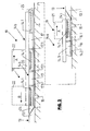
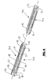
- the Fig. 5 shows in a schematic representation again one of the two front rails 14a, together with an elongated damping device 26, which consists essentially of the two, made of plastic and in the longitudinal direction L of the ski body 1 relative to each other slidable housing parts 27 and 28.
- the damping device 26 is attached to the top of the ski body in such a way that it is oriented with its longitudinal extent in the direction of the longitudinal axis L of the ski body. With a partial length of the housing portion 27, the damping device 26 is disposed between the two front rails 14a and otherwise protrudes beyond the front end of these rails towards the front end of the ski body 1 out.
- the housing part 27 is connected with its the front end of the ski body 1 remote from the rear end via two lateral projections 29 hingedly connected to a respective rail 14a, but not slidably held on this rail in profile rail longitudinal direction.
- This is realized, for example, in that the projection 29 is received in a lateral groove formed by the H-profile of the respective profile rail 14a and after fastening of the binding or the binding plate 20 by a fastening section 23 engaging behind the upper profile section 14.1 against displacement in the longitudinal direction the rail 14a is secured and / or the housing part 27 is supported on the binding or binding plate 20.
- the front end of the damping element 26 or the housing part 28 forming this end is connected in a suitable manner, for example by screwing to the upper side of the ski body 1.
- the two housing parts 27 and 28 are located above the ski body upper side 4, ie far above a plane that the neutral plane with respect to the distribution of compressive and tensile forces during flexing, ie when bending the ski body 1 about axes perpendicular to the longitudinal direction L of Ski stressess forms, the two housing parts 27 and 28 are moved relative to each other during flexing.
- spring and damping elements are added, which in the Fig. 5 are generally designated 30 and in the relative movement of the two housing parts 27 and 28 (double arrow C) are deformed for a resilient or damping effect.
- These spring and damping means are formed for example by at least one spring made of spring steel and / or damping bodies or elements of a deformable material, for example of an elastic gel.
- the advantage of the coupling of the damping device 26 to the profile rail system is, inter alia, that an additional attachment for the rear housing part 27 on the ski body 1 is not required, and especially in that when pushing the formation plate 20, ie when mounting the binding by axial Moving the projections 29 in the rails 14 a movement of the housing part 27 relative to the housing part 28 under biasing of the spring and damping means 30 is possible.
Landscapes
- Road Paving Structures (AREA)
- Escalators And Moving Walkways (AREA)
- Fittings On The Vehicle Exterior For Carrying Loads, And Devices For Holding Or Mounting Articles (AREA)
Applications Claiming Priority (5)
| Application Number | Priority Date | Filing Date | Title |
|---|---|---|---|
| DE202006010314 | 2006-06-30 | ||
| DE102006032019 | 2006-07-10 | ||
| DE202006010714 | 2006-07-10 | ||
| DE102006034869A DE102006034869A1 (de) | 2006-06-30 | 2006-07-25 | Schneegleitbrett, insbesondere Ski |
| EP07012632.1A EP1872836B1 (fr) | 2006-06-30 | 2007-06-28 | Planche de surf sur neige, en particulier ski, avec interruption dans les rails profilés |
Related Parent Applications (1)
| Application Number | Title | Priority Date | Filing Date |
|---|---|---|---|
| EP07012632.1 Division | 2007-06-28 |
Publications (1)
| Publication Number | Publication Date |
|---|---|
| EP2368607A1 true EP2368607A1 (fr) | 2011-09-28 |
Family
ID=38565948
Family Applications (2)
| Application Number | Title | Priority Date | Filing Date |
|---|---|---|---|
| EP11000885A Withdrawn EP2368607A1 (fr) | 2006-06-30 | 2007-06-28 | Planche de surf sur neige, en particulier un ski, avec rails de guidage associés à un système d'amortissement |
| EP07012632.1A Not-in-force EP1872836B1 (fr) | 2006-06-30 | 2007-06-28 | Planche de surf sur neige, en particulier ski, avec interruption dans les rails profilés |
Family Applications After (1)
| Application Number | Title | Priority Date | Filing Date |
|---|---|---|---|
| EP07012632.1A Not-in-force EP1872836B1 (fr) | 2006-06-30 | 2007-06-28 | Planche de surf sur neige, en particulier ski, avec interruption dans les rails profilés |
Country Status (2)
| Country | Link |
|---|---|
| EP (2) | EP2368607A1 (fr) |
| DE (1) | DE102006034869A1 (fr) |
Families Citing this family (2)
| Publication number | Priority date | Publication date | Assignee | Title |
|---|---|---|---|---|
| DE202014010597U1 (de) | 2014-04-02 | 2016-02-02 | Brigitte Weber | Verbindungssystem für Gleitbrett |
| NO2715057T3 (fr) | 2014-04-02 | 2018-02-10 |
Citations (6)
| Publication number | Priority date | Publication date | Assignee | Title |
|---|---|---|---|---|
| DE10062884A1 (de) | 2000-06-09 | 2002-05-02 | Voelkl Sports Gmbh & Co Kg | Gleitbrett, insbesondere Ski |
| WO2002049728A1 (fr) | 2000-12-19 | 2002-06-27 | Elan, D.D. | Ski ou instrument de glisse analogue integrant un ensemble pour fixer une fixation de ski de maniere reglable |
| US20030193169A1 (en) * | 2002-04-11 | 2003-10-16 | Hans Holzinger | Baseplate and fixture for ski or snowboard binding |
| DE202004019710U1 (de) * | 2004-12-21 | 2005-04-07 | Blizzard Sport Ges M B H | Gleitbrett, insbesondere Alpinski oder Snowboard |
| DE102004004990A1 (de) * | 2004-01-30 | 2005-09-01 | Marker Deutschland Gmbh | Plattenförmige Bindungsträgeranordnung für Schneegleitbretter bzw. Ski |
| EP1611927A1 (fr) | 2004-07-02 | 2006-01-04 | Völkl Sports GmbH & Co. KG | Planche de glisse sur neige |
Family Cites Families (3)
| Publication number | Priority date | Publication date | Assignee | Title |
|---|---|---|---|---|
| FR2635465B1 (fr) * | 1988-08-17 | 1990-11-16 | Salomon Sa | Fixation de securite pour ski |
| FR2689411B1 (fr) * | 1992-04-01 | 1994-06-03 | Salomon Sa | Ski comprenant une embase et un raidisseur en deux parties relie a l'embase. |
| ATE433789T1 (de) * | 2005-01-07 | 2009-07-15 | Tyrolia Technology Gmbh | Gleitbrett, insbesondere ski |
-
2006
- 2006-07-25 DE DE102006034869A patent/DE102006034869A1/de not_active Withdrawn
-
2007
- 2007-06-28 EP EP11000885A patent/EP2368607A1/fr not_active Withdrawn
- 2007-06-28 EP EP07012632.1A patent/EP1872836B1/fr not_active Not-in-force
Patent Citations (6)
| Publication number | Priority date | Publication date | Assignee | Title |
|---|---|---|---|---|
| DE10062884A1 (de) | 2000-06-09 | 2002-05-02 | Voelkl Sports Gmbh & Co Kg | Gleitbrett, insbesondere Ski |
| WO2002049728A1 (fr) | 2000-12-19 | 2002-06-27 | Elan, D.D. | Ski ou instrument de glisse analogue integrant un ensemble pour fixer une fixation de ski de maniere reglable |
| US20030193169A1 (en) * | 2002-04-11 | 2003-10-16 | Hans Holzinger | Baseplate and fixture for ski or snowboard binding |
| DE102004004990A1 (de) * | 2004-01-30 | 2005-09-01 | Marker Deutschland Gmbh | Plattenförmige Bindungsträgeranordnung für Schneegleitbretter bzw. Ski |
| EP1611927A1 (fr) | 2004-07-02 | 2006-01-04 | Völkl Sports GmbH & Co. KG | Planche de glisse sur neige |
| DE202004019710U1 (de) * | 2004-12-21 | 2005-04-07 | Blizzard Sport Ges M B H | Gleitbrett, insbesondere Alpinski oder Snowboard |
Also Published As
| Publication number | Publication date |
|---|---|
| EP1872836B1 (fr) | 2013-11-20 |
| DE102006034869A1 (de) | 2008-01-03 |
| EP1872836A2 (fr) | 2008-01-02 |
| EP1872836A3 (fr) | 2008-11-19 |
Similar Documents
| Publication | Publication Date | Title |
|---|---|---|
| EP0635286B1 (fr) | Planche de glisse | |
| EP1161972B1 (fr) | Planche de glisse, notamment ski ainsi qu'un système de rails profilés pour une telle planche de glisse | |
| WO2016050345A1 (fr) | Transmission à chaîne munie de plusieurs éléments de glissement | |
| EP1297869B1 (fr) | Planche de glisse ,speciallement un ski | |
| EP1872836B1 (fr) | Planche de surf sur neige, en particulier ski, avec interruption dans les rails profilés | |
| EP1611927B1 (fr) | Planche de glisse sur neige | |
| AT500252B1 (de) | Gleitbrett, insbesondere ski | |
| EP2067506B1 (fr) | Planche de surf sur neige, en particulier ski, avec fixation du rail de coulissement par des chevilles | |
| DE10152438B4 (de) | Schneegleitbrett, insbesondere Ski sowie Spreizvorrichtung für ein Schneegleitbrett | |
| DE10049011A1 (de) | Montageplatte für eine Kupplungsvorrichtung auf einer Gleitvorrichtung | |
| DE3806061A1 (de) | Verbesserter, in zwei separate elemente zerlegbarer monoski | |
| EP2061566B1 (fr) | Dispositif de réglage de planches de glisse sur la neige, notamment de skis, et planche de glisse sur la neige comportant un tel dispositif de réglage | |
| EP1787691B1 (fr) | Planche de glisse sur neige et élément de couverture pour planche de glisse sur neige | |
| DE102005049478B4 (de) | Schneegleitbrett, insbesondere Snowboard | |
| EP1882505B1 (fr) | Voie pour installation de trains en modèle réduit | |
| DE10062884A1 (de) | Gleitbrett, insbesondere Ski | |
| EP1163937A2 (fr) | Plaque de surélévation | |
| EP1582240B1 (fr) | Planche de glisse notamment une planche a neige | |
| DE29603405U1 (de) | Tragplatte | |
| DE4209992C2 (de) | Ski | |
| DE10138654A1 (de) | Bindungsplattensystem für Schneegleitbretter, indbesondere Snowboards sowie Schneegleitbrett mit einem solchen Bindungsplattensystem | |
| EP1100599A1 (fr) | Monoski | |
| EP2210650B1 (fr) | Plaque de connexion en plusieurs parties destinée à agencer une fixation de ski sur un ski | |
| DE19614184A1 (de) | Ski, Snowboard oder dergleichen Schneegleitelement | |
| DE102005028256A1 (de) | Stabförmiges Gleitprofil |
Legal Events
| Date | Code | Title | Description |
|---|---|---|---|
| PUAI | Public reference made under article 153(3) epc to a published international application that has entered the european phase |
Free format text: ORIGINAL CODE: 0009012 |
|
| AC | Divisional application: reference to earlier application |
Ref document number: 1872836 Country of ref document: EP Kind code of ref document: P |
|
| AK | Designated contracting states |
Kind code of ref document: A1 Designated state(s): AT CH DE FR IT LI |
|
| 17P | Request for examination filed |
Effective date: 20120215 |
|
| 17Q | First examination report despatched |
Effective date: 20150811 |
|
| STAA | Information on the status of an ep patent application or granted ep patent |
Free format text: STATUS: THE APPLICATION IS DEEMED TO BE WITHDRAWN |
|
| 18D | Application deemed to be withdrawn |
Effective date: 20151222 |