EP2368691A2 - Procédé de fabrication de récipients en matière synthétique et dispositif pour réaliser le procédé - Google Patents
Procédé de fabrication de récipients en matière synthétique et dispositif pour réaliser le procédé Download PDFInfo
- Publication number
- EP2368691A2 EP2368691A2 EP11151419A EP11151419A EP2368691A2 EP 2368691 A2 EP2368691 A2 EP 2368691A2 EP 11151419 A EP11151419 A EP 11151419A EP 11151419 A EP11151419 A EP 11151419A EP 2368691 A2 EP2368691 A2 EP 2368691A2
- Authority
- EP
- European Patent Office
- Prior art keywords
- blow molding
- preforms
- molding machine
- different
- plastic containers
- Prior art date
- Legal status (The legal status is an assumption and is not a legal conclusion. Google has not performed a legal analysis and makes no representation as to the accuracy of the status listed.)
- Granted
Links
- 239000004033 plastic Substances 0.000 title claims abstract description 85
- 229920003023 plastic Polymers 0.000 title claims abstract description 85
- 238000004519 manufacturing process Methods 0.000 title claims abstract description 41
- 238000000034 method Methods 0.000 title claims description 30
- 238000000071 blow moulding Methods 0.000 claims abstract description 147
- 238000007664 blowing Methods 0.000 claims description 72
- 230000001954 sterilising effect Effects 0.000 claims description 21
- 238000004659 sterilization and disinfection Methods 0.000 claims description 19
- 230000008569 process Effects 0.000 claims description 12
- 238000001746 injection moulding Methods 0.000 claims description 10
- 238000012545 processing Methods 0.000 claims description 10
- 238000007689 inspection Methods 0.000 claims description 8
- 238000010438 heat treatment Methods 0.000 description 104
- 238000012546 transfer Methods 0.000 description 16
- 238000002372 labelling Methods 0.000 description 12
- 238000002347 injection Methods 0.000 description 11
- 239000007924 injection Substances 0.000 description 11
- 238000010102 injection blow moulding Methods 0.000 description 11
- 238000001514 detection method Methods 0.000 description 7
- 230000005855 radiation Effects 0.000 description 7
- 239000000945 filler Substances 0.000 description 6
- 239000000126 substance Substances 0.000 description 6
- 238000000748 compression moulding Methods 0.000 description 5
- 239000000463 material Substances 0.000 description 5
- 239000000203 mixture Substances 0.000 description 5
- 239000005020 polyethylene terephthalate Substances 0.000 description 5
- 229920000139 polyethylene terephthalate Polymers 0.000 description 5
- 239000006096 absorbing agent Substances 0.000 description 4
- 239000011248 coating agent Substances 0.000 description 4
- 238000000576 coating method Methods 0.000 description 4
- 241000196324 Embryophyta Species 0.000 description 3
- 239000004743 Polypropylene Substances 0.000 description 3
- 238000010521 absorption reaction Methods 0.000 description 3
- 239000000872 buffer Substances 0.000 description 3
- 238000006243 chemical reaction Methods 0.000 description 3
- 230000003750 conditioning effect Effects 0.000 description 3
- 238000001816 cooling Methods 0.000 description 3
- 238000007654 immersion Methods 0.000 description 3
- 238000005259 measurement Methods 0.000 description 3
- 239000004793 Polystyrene Substances 0.000 description 2
- 239000004372 Polyvinyl alcohol Substances 0.000 description 2
- 230000008901 benefit Effects 0.000 description 2
- 230000008859 change Effects 0.000 description 2
- 230000001143 conditioned effect Effects 0.000 description 2
- 238000000465 moulding Methods 0.000 description 2
- 230000003287 optical effect Effects 0.000 description 2
- -1 polyethylene terephthalate Polymers 0.000 description 2
- 229920002451 polyvinyl alcohol Polymers 0.000 description 2
- 239000011358 absorbing material Substances 0.000 description 1
- 230000004888 barrier function Effects 0.000 description 1
- 235000013361 beverage Nutrition 0.000 description 1
- 235000013949 black currant juice Nutrition 0.000 description 1
- 239000000919 ceramic Substances 0.000 description 1
- 238000004140 cleaning Methods 0.000 description 1
- 239000003086 colorant Substances 0.000 description 1
- 238000009826 distribution Methods 0.000 description 1
- ZINJLDJMHCUBIP-UHFFFAOYSA-N ethametsulfuron-methyl Chemical compound CCOC1=NC(NC)=NC(NC(=O)NS(=O)(=O)C=2C(=CC=CC=2)C(=O)OC)=N1 ZINJLDJMHCUBIP-UHFFFAOYSA-N 0.000 description 1
- 239000012530 fluid Substances 0.000 description 1
- 230000007257 malfunction Effects 0.000 description 1
- 238000012986 modification Methods 0.000 description 1
- 230000004048 modification Effects 0.000 description 1
- 235000015205 orange juice Nutrition 0.000 description 1
- 229920001155 polypropylene Polymers 0.000 description 1
- 229920002223 polystyrene Polymers 0.000 description 1
- 238000010926 purge Methods 0.000 description 1
- 238000005507 spraying Methods 0.000 description 1
- 238000003860 storage Methods 0.000 description 1
- XLYOFNOQVPJJNP-UHFFFAOYSA-N water Substances O XLYOFNOQVPJJNP-UHFFFAOYSA-N 0.000 description 1
Images





Classifications
-
- B—PERFORMING OPERATIONS; TRANSPORTING
- B29—WORKING OF PLASTICS; WORKING OF SUBSTANCES IN A PLASTIC STATE IN GENERAL
- B29C—SHAPING OR JOINING OF PLASTICS; SHAPING OF MATERIAL IN A PLASTIC STATE, NOT OTHERWISE PROVIDED FOR; AFTER-TREATMENT OF THE SHAPED PRODUCTS, e.g. REPAIRING
- B29C49/00—Blow-moulding, i.e. blowing a preform or parison to a desired shape within a mould; Apparatus therefor
- B29C49/28—Blow-moulding apparatus
- B29C49/30—Blow-moulding apparatus having movable moulds or mould parts
- B29C49/36—Blow-moulding apparatus having movable moulds or mould parts rotatable about one axis
-
- B—PERFORMING OPERATIONS; TRANSPORTING
- B29—WORKING OF PLASTICS; WORKING OF SUBSTANCES IN A PLASTIC STATE IN GENERAL
- B29C—SHAPING OR JOINING OF PLASTICS; SHAPING OF MATERIAL IN A PLASTIC STATE, NOT OTHERWISE PROVIDED FOR; AFTER-TREATMENT OF THE SHAPED PRODUCTS, e.g. REPAIRING
- B29C49/00—Blow-moulding, i.e. blowing a preform or parison to a desired shape within a mould; Apparatus therefor
- B29C49/42—Component parts, details or accessories; Auxiliary operations
- B29C49/4205—Handling means, e.g. transfer, loading or discharging means
- B29C49/42065—Means specially adapted for transporting preforms
-
- B—PERFORMING OPERATIONS; TRANSPORTING
- B29—WORKING OF PLASTICS; WORKING OF SUBSTANCES IN A PLASTIC STATE IN GENERAL
- B29C—SHAPING OR JOINING OF PLASTICS; SHAPING OF MATERIAL IN A PLASTIC STATE, NOT OTHERWISE PROVIDED FOR; AFTER-TREATMENT OF THE SHAPED PRODUCTS, e.g. REPAIRING
- B29C49/00—Blow-moulding, i.e. blowing a preform or parison to a desired shape within a mould; Apparatus therefor
- B29C49/42—Component parts, details or accessories; Auxiliary operations
- B29C49/78—Measuring, controlling or regulating
- B29C49/786—Temperature
- B29C2049/7861—Temperature of the preform
-
- B—PERFORMING OPERATIONS; TRANSPORTING
- B29—WORKING OF PLASTICS; WORKING OF SUBSTANCES IN A PLASTIC STATE IN GENERAL
- B29C—SHAPING OR JOINING OF PLASTICS; SHAPING OF MATERIAL IN A PLASTIC STATE, NOT OTHERWISE PROVIDED FOR; AFTER-TREATMENT OF THE SHAPED PRODUCTS, e.g. REPAIRING
- B29C2949/00—Indexing scheme relating to blow-moulding
- B29C2949/07—Preforms or parisons characterised by their configuration
- B29C2949/0715—Preforms or parisons characterised by their configuration the preform having one end closed
-
- B—PERFORMING OPERATIONS; TRANSPORTING
- B29—WORKING OF PLASTICS; WORKING OF SUBSTANCES IN A PLASTIC STATE IN GENERAL
- B29C—SHAPING OR JOINING OF PLASTICS; SHAPING OF MATERIAL IN A PLASTIC STATE, NOT OTHERWISE PROVIDED FOR; AFTER-TREATMENT OF THE SHAPED PRODUCTS, e.g. REPAIRING
- B29C49/00—Blow-moulding, i.e. blowing a preform or parison to a desired shape within a mould; Apparatus therefor
- B29C49/006—Blow-moulding plants, e.g. using several blow-moulding apparatuses cooperating
-
- B—PERFORMING OPERATIONS; TRANSPORTING
- B29—WORKING OF PLASTICS; WORKING OF SUBSTANCES IN A PLASTIC STATE IN GENERAL
- B29C—SHAPING OR JOINING OF PLASTICS; SHAPING OF MATERIAL IN A PLASTIC STATE, NOT OTHERWISE PROVIDED FOR; AFTER-TREATMENT OF THE SHAPED PRODUCTS, e.g. REPAIRING
- B29C49/00—Blow-moulding, i.e. blowing a preform or parison to a desired shape within a mould; Apparatus therefor
- B29C49/02—Combined blow-moulding and manufacture of the preform or the parison
- B29C49/06—Injection blow-moulding
-
- B—PERFORMING OPERATIONS; TRANSPORTING
- B29—WORKING OF PLASTICS; WORKING OF SUBSTANCES IN A PLASTIC STATE IN GENERAL
- B29C—SHAPING OR JOINING OF PLASTICS; SHAPING OF MATERIAL IN A PLASTIC STATE, NOT OTHERWISE PROVIDED FOR; AFTER-TREATMENT OF THE SHAPED PRODUCTS, e.g. REPAIRING
- B29C49/00—Blow-moulding, i.e. blowing a preform or parison to a desired shape within a mould; Apparatus therefor
- B29C49/28—Blow-moulding apparatus
- B29C49/28012—Blow-moulding apparatus using several moulds whereby at least one mould is different in at least one feature, e.g. size or shape
-
- B—PERFORMING OPERATIONS; TRANSPORTING
- B29—WORKING OF PLASTICS; WORKING OF SUBSTANCES IN A PLASTIC STATE IN GENERAL
- B29C—SHAPING OR JOINING OF PLASTICS; SHAPING OF MATERIAL IN A PLASTIC STATE, NOT OTHERWISE PROVIDED FOR; AFTER-TREATMENT OF THE SHAPED PRODUCTS, e.g. REPAIRING
- B29C49/00—Blow-moulding, i.e. blowing a preform or parison to a desired shape within a mould; Apparatus therefor
- B29C49/42—Component parts, details or accessories; Auxiliary operations
- B29C49/42378—Handling malfunction
-
- B—PERFORMING OPERATIONS; TRANSPORTING
- B29—WORKING OF PLASTICS; WORKING OF SUBSTANCES IN A PLASTIC STATE IN GENERAL
- B29C—SHAPING OR JOINING OF PLASTICS; SHAPING OF MATERIAL IN A PLASTIC STATE, NOT OTHERWISE PROVIDED FOR; AFTER-TREATMENT OF THE SHAPED PRODUCTS, e.g. REPAIRING
- B29C49/00—Blow-moulding, i.e. blowing a preform or parison to a desired shape within a mould; Apparatus therefor
- B29C49/42—Component parts, details or accessories; Auxiliary operations
- B29C49/42378—Handling malfunction
- B29C49/4238—Ejecting defective preforms or products
-
- B—PERFORMING OPERATIONS; TRANSPORTING
- B29—WORKING OF PLASTICS; WORKING OF SUBSTANCES IN A PLASTIC STATE IN GENERAL
- B29C—SHAPING OR JOINING OF PLASTICS; SHAPING OF MATERIAL IN A PLASTIC STATE, NOT OTHERWISE PROVIDED FOR; AFTER-TREATMENT OF THE SHAPED PRODUCTS, e.g. REPAIRING
- B29C49/00—Blow-moulding, i.e. blowing a preform or parison to a desired shape within a mould; Apparatus therefor
- B29C49/42—Component parts, details or accessories; Auxiliary operations
- B29C49/42403—Purging or cleaning the blow-moulding apparatus
- B29C49/42405—Sterilizing
-
- B—PERFORMING OPERATIONS; TRANSPORTING
- B29—WORKING OF PLASTICS; WORKING OF SUBSTANCES IN A PLASTIC STATE IN GENERAL
- B29C—SHAPING OR JOINING OF PLASTICS; SHAPING OF MATERIAL IN A PLASTIC STATE, NOT OTHERWISE PROVIDED FOR; AFTER-TREATMENT OF THE SHAPED PRODUCTS, e.g. REPAIRING
- B29C49/00—Blow-moulding, i.e. blowing a preform or parison to a desired shape within a mould; Apparatus therefor
- B29C49/42—Component parts, details or accessories; Auxiliary operations
- B29C49/42407—Procedures for start-up or material change
-
- B—PERFORMING OPERATIONS; TRANSPORTING
- B29—WORKING OF PLASTICS; WORKING OF SUBSTANCES IN A PLASTIC STATE IN GENERAL
- B29C—SHAPING OR JOINING OF PLASTICS; SHAPING OF MATERIAL IN A PLASTIC STATE, NOT OTHERWISE PROVIDED FOR; AFTER-TREATMENT OF THE SHAPED PRODUCTS, e.g. REPAIRING
- B29C49/00—Blow-moulding, i.e. blowing a preform or parison to a desired shape within a mould; Apparatus therefor
- B29C49/42—Component parts, details or accessories; Auxiliary operations
- B29C49/64—Heating or cooling preforms, parisons or blown articles
- B29C49/6409—Thermal conditioning of preforms
-
- B—PERFORMING OPERATIONS; TRANSPORTING
- B29—WORKING OF PLASTICS; WORKING OF SUBSTANCES IN A PLASTIC STATE IN GENERAL
- B29C—SHAPING OR JOINING OF PLASTICS; SHAPING OF MATERIAL IN A PLASTIC STATE, NOT OTHERWISE PROVIDED FOR; AFTER-TREATMENT OF THE SHAPED PRODUCTS, e.g. REPAIRING
- B29C49/00—Blow-moulding, i.e. blowing a preform or parison to a desired shape within a mould; Apparatus therefor
- B29C49/42—Component parts, details or accessories; Auxiliary operations
- B29C49/64—Heating or cooling preforms, parisons or blown articles
- B29C49/6409—Thermal conditioning of preforms
- B29C49/6436—Thermal conditioning of preforms characterised by temperature differential
- B29C49/6445—Thermal conditioning of preforms characterised by temperature differential through the preform length
-
- B—PERFORMING OPERATIONS; TRANSPORTING
- B29—WORKING OF PLASTICS; WORKING OF SUBSTANCES IN A PLASTIC STATE IN GENERAL
- B29K—INDEXING SCHEME ASSOCIATED WITH SUBCLASSES B29B, B29C OR B29D, RELATING TO MOULDING MATERIALS OR TO MATERIALS FOR MOULDS, REINFORCEMENTS, FILLERS OR PREFORMED PARTS, e.g. INSERTS
- B29K2067/00—Use of polyesters or derivatives thereof, as moulding material
-
- B—PERFORMING OPERATIONS; TRANSPORTING
- B29—WORKING OF PLASTICS; WORKING OF SUBSTANCES IN A PLASTIC STATE IN GENERAL
- B29K—INDEXING SCHEME ASSOCIATED WITH SUBCLASSES B29B, B29C OR B29D, RELATING TO MOULDING MATERIALS OR TO MATERIALS FOR MOULDS, REINFORCEMENTS, FILLERS OR PREFORMED PARTS, e.g. INSERTS
- B29K2067/00—Use of polyesters or derivatives thereof, as moulding material
- B29K2067/003—PET, i.e. poylethylene terephthalate
-
- B—PERFORMING OPERATIONS; TRANSPORTING
- B29—WORKING OF PLASTICS; WORKING OF SUBSTANCES IN A PLASTIC STATE IN GENERAL
- B29K—INDEXING SCHEME ASSOCIATED WITH SUBCLASSES B29B, B29C OR B29D, RELATING TO MOULDING MATERIALS OR TO MATERIALS FOR MOULDS, REINFORCEMENTS, FILLERS OR PREFORMED PARTS, e.g. INSERTS
- B29K2067/00—Use of polyesters or derivatives thereof, as moulding material
- B29K2067/04—Polyesters derived from hydroxycarboxylic acids
- B29K2067/046—PLA, i.e. polylactic acid or polylactide
-
- B—PERFORMING OPERATIONS; TRANSPORTING
- B29—WORKING OF PLASTICS; WORKING OF SUBSTANCES IN A PLASTIC STATE IN GENERAL
- B29L—INDEXING SCHEME ASSOCIATED WITH SUBCLASS B29C, RELATING TO PARTICULAR ARTICLES
- B29L2031/00—Other particular articles
- B29L2031/712—Containers; Packaging elements or accessories, Packages
- B29L2031/7158—Bottles
Definitions
- the invention relates to a method for producing plastic containers by means of a blow molding machine.
- Product packages with different products are being offered more and more frequently.
- a six-carrier beverage there may be two bottles of orange juice, two bottles of blackcurrant juice, and two bottles of water.
- the products are usually produced individually on a filling line, packaged and then picked to form a product package.
- the different products are often filled into different plastic containers, for example in plastic containers of different colors.
- the different plastic containers are usually produced by means of a blow molding machine in several production runs, wherein in each of the production runs only one type of plastic container is produced.
- the object of the present invention is to provide an improved method for producing plastic containers by means of a blow molding machine. This object is achieved by a method according to claim 1.
- the invention provides a method for producing plastic containers by means of a blow molding machine, characterized in that the blow molding machine is operated such that at least two mutually different plastic containers are discharged from the blow molding machine within a production run.
- the plastic containers may in particular be plastic bottles, for example PET (polyethylene terephthalate) bottles.
- In a production run means in this context that the at least two mutually different plastic containers are applied in one pass, so between the dispensing of a first plastic container and a second, different, plastic container no manual modifications to the blow molding machine are necessary.
- a production run a production of several Plastic containers understood without a stoppage of the blow molding machine for converting the blow molding machine.
- blow molding machines that are operated as cycle machines, the production over several cycles can be understood as one production cycle.
- the blow molding machine may include a machine protection, in particular wherein the machine protection is not opened within a production run.
- the plastic containers can be continuously transported away from the blow molding machine within a production run. This applies in particular to rotating machines.
- the different containers can be transported away on the same transport path or the same transport route.
- the applied plastic containers can be transferred to a further treatment element, in particular a filler, a labeling device and / or a sterilization device.
- plastic containers differ from one another in at least one physical, chemical and / or geometric property.
- the operation of the blow molding machine can be understood as controlling and / or adjusting and / or forming.
- the at least two mutually different plastic containers may in particular correspond to at least two mutually different types of plastic containers.
- one or more plastic containers of a first type of plastic container and one or more plastic containers of at least one second type of plastic container can be dispensed from the blowing machine in one production run.
- the at least two mutually different plastic containers may consist of preforms, in particular of at least two mutually different preforms or similar preforms.
- the preforms, also called preforms, may comprise a plastic, in particular PET.
- the method for producing plastic containers may also include feeding the preforms.
- the blow molding machine may correspond to a manufacturing machine for producing plastic containers.
- the blowing machine may in particular comprise a heating device and a blow molding machine.
- the method may include thermally conditioning the preforms in the heater and / or expanding the preforms in the blow molding machine.
- the thermal conditioning may in particular comprise heating and / or cooling of the preforms.
- the blow molding machine may also correspond to an injection molding machine for injection molding plastic containers in one or more end molds or a compression molding machine for molding the plastic containers.
- the at least two mutually different plastic containers and / or different preforms differ from each other in one or more physical, chemical and / or geometric properties.
- the plastic containers and / or preforms may have different geometric properties, for example different sizes, neck diameters and / or lengths.
- the different plastic containers and / or preforms may also differ in optical properties, for example color and / or transparency, and / or in the material, in particular in the material composition.
- the different plastic containers and / or preforms may include different amounts of an infrared absorbing material.
- the different plastic containers and / or preforms may also have different threads for different closures.
- the different plastic containers and / or preforms may also have different positions for indicators for the attachment of different or similar closures.
- As an indicator for example, a notch or a bulge on the edge of a support ring of the plastic containers and / or preforms serve.
- the different plastic containers and / or preforms may also comprise different materials or consist of different materials.
- plastic containers made of PET and PP polypropylene
- PET polypropylene
- PS polystyrene
- PLA polyvinyl alcohol
- the at least two different plastic containers and / or preforms may also have a different weight, a different stability and / or a different coating.
- an additional coating module in particular in front of the blow molding machine, for example a blowing wheel, can be provided.
- the at least two different plastic containers and / or the preforms can each be treated within the blow molding machine with at least one treatment parameter, the at least one treatment parameter for the at least two different plastic containers and / or the preforms being different and / or having a different value.
- the preforms can be heated in a first step, and formed in a second step by means of a blowing process, in particular a stretch blow molding, to the desired plastic containers.
- the heating of the preforms can be carried out in a heating device of the blow molding machine.
- a heating device of the blow molding machine can be operated, in particular controlled, in such a way that the preforms are heated to different temperatures.
- different temperatures for the blowing process, in particular the stretch blow molding can be selected for different preforms from each other.
- the heating device of the blow molding machine can in particular be operated such that the preforms can be heated to different temperatures in different regions of a longitudinal axis and / or in different regions in the axial direction of the preforms.
- the heating device of the blow molding machine may, for example, be a conventional stationary, linear or continuous furnace.
- the heating device may comprise heating elements, in particular wherein each heating element is used for the conditioning of all preforms, or individual preforms individually associated cavities, in particular heating pockets or, in microwave ovens, resonators having.
- a small number of preforms usually one, individually tempered.
- the preforms In the case of a one-step process, ie if the preforms are produced by injection molding and still heated by the injection molding process are transferred to the heating device of the blow molding machine, the preforms can be cooled in the heater.
- the at least two mutually different plastic containers can also be injection-molded in one or more end shapes, in particular in mutually different end shapes. In this case, it is possible to dispense with the process steps in which preforms are supplied, conditioned and expanded to form plastic containers.
- the blow molding machine can comprise different treatment units.
- the treatment units can be, for example, heating elements and / or blowing stations.
- the preforms can be assigned to different treatment units.
- the blow molding machine can be controlled such that at least two preforms are assigned to different treatment units, in particular such that at least two mutually different plastic containers are applied in one production run.
- the blow molding machine may comprise at least two blowing stations, wherein the blowing machine is controlled such that the preforms are assigned to different blow molding stations.
- the blow molding stations can differ in different treatment parameters such as the geometry of the blow mold, the stretching parameters used and / or the blowing parameters used, for example pre-blow pressure, finished blow pressure, rinsing time and / or switching times for the respective pressures.
- a heating device in particular heating elements of the heating device, can be controlled and / or designed such that a preform can be provided with a predetermined heating profile or temperature profile ("preferential heating").
- preforms can be provided with different temperature profiles.
- the preforms can be provided in the circumferential direction and / or in the longitudinal direction with a temperature profile.
- the temperature may be controlled at one or more predetermined locations or areas of a preform.
- At least two preforms may be treated in the heater using mutually different treatment parameter values.
- the treatment parameters of the heating device in particular the heating elements of the heating device, a rotational speed of the preforms, an introduced heat per area to be heated (layer or longitudinal area (preferential heating)), a distance to a radiant heater, a Throughput speed through the heater, a shielding time of certain areas of a preform, a shielding position, a wavelength of the radiation, a radiation type and / or a field strength of a microwave radiation.
- the preforms can be introduced into the blow molding machine in a predetermined order.
- different from each other preforms can then be supplied to the corresponding, in particular different, treatment units of the blow molding machine in a simple manner.
- the preforms can also be moved at least partially on different transport routes through the blow molding machine.
- different preforms from each other can be processed in different ways.
- a first preform can be moved on a first transport path through a heating device of the blow molding machine, while a second preform is moved on a second, different from the first transport path, transport path through the heater.
- the different transport routes can in particular be of different lengths.
- a different heating time for the preforms can be achieved.
- the different transport paths, the different preforms also on different heating elements, in particular on differently shaped and / or controlled heating elements, pass, so that they are heated differently.
- the preforms can also be moved at different speeds by the blow molding machine, in particular by a heating device of the blow molding machine.
- the heating device of the blowing machine may also comprise at least one shielding device.
- the at least one shielding device can be moved with the preform by the heating device.
- the shielding device may also be used for shielding certain areas of the preforms in the circumferential direction.
- the shielding device can be operated differently for different preforms, in particular controlled.
- the time of lifting and / or lowering of the shielding device can be chosen differently for different preforms.
- the orientation of the shielding plate, for example in the circumferential direction of the preforms, can be selected accordingly.
- the method for producing plastic containers may also include automatic detection of, in particular different, preforms.
- the preforms can be supplied in a simple manner selectively to the correct treatment unit of the blow molding machine.
- the automatic detection may include detecting at least one physical, chemical and / or geometric property of a preform.
- At least one recognized preform can be assigned automatically, for example via one or more switches, to at least one treatment unit.
- At least one treatment parameter can be assigned to the at least one identified preform.
- the value of at least one treatment parameter corresponding to the identified preform can be selected, and the blow molding machine can be operated such that the recognized preform in the blow molding machine is treated with the selected treatment parameter value.
- the at least one treatment unit can correspond to a transport mandrel, a transport clamp, an inner and / or outer gripper, a blow mold, a heating element, a sterilization nozzle, a sorting unit and / or a conveying device for conveying the plastic containers and / or preforms.
- the at least one treatment parameter may correspond to the geometry of the blow mold, a stretching parameter and / or blowing parameter used, for example a pre-blowing pressure, a finished blowing pressure, a rinsing time and / or a switching time for the respective pressures.
- the automatic recognition of the preforms can be performed, for example, optically, in particular by a camera.
- the automatic detection of the preforms can be integrated, for example, in a device which is provided for measuring the infrared absorption coefficient.
- the different preforms can be introduced into the blow molding machine based on a result of the automatic recognition.
- the preforms can be removed from a chute and fed to a sorting unit, in which the preforms are sorted by means of automatic detection and then introduced into the blow molding machine, in particular in a predetermined sequence.
- the method for producing the plastic containers may also include producing the preforms, in particular by injection molding or by compression molding.
- the production of the plastic containers can thus take place in an injection blow molding machine.
- the combined injection blow molding has the advantage that the heat which is still present in the preform from injection molding can be obtained.
- the preform can be profiled by targeted cooling and / or heating.
- An injection module of the injection blow molding machine can in particular be operated in such a way that different preforms from each other can be produced.
- the injection module may be designed such that at least two mutually different preforms can be injection-molded in different shapes.
- a plurality of injection modules may be provided, wherein each injection module generates a type or a sort of preform, wherein the preforms of at least two injection modules differ from each other.
- the amount of an infrared absorber introduced into the preform can be controlled in one or more injection modules. For example, at least two mutually different preforms can be produced, wherein the amount and / or the profiling of an infrared absorber in the at least two mutually different preforms differ from each other.
- the amount of plastic discharged from an extruder can be controlled to produce at least two mutually different preforms.
- the method of manufacturing the plastic containers may also include sterilizing the preforms, particularly where the sterilization process differs for different preforms.
- the invention also provides a blow molding machine for producing plastic containers, wherein the blow molding machine is designed such that at least two mutually different plastic containers can be dispensed from the blow molding machine in one production pass.
- the blow molding machine can be a stretch blow molding machine and / or an injection blow molding machine.
- the blowing machine may have one or more of the above features.
- the blow molding machine may comprise at least two blowing stations which are different from one another and / or operated differently.
- the blow molding machine can also be different and / or differently operated heating elements, injection modules and / or sterilization elements.
- the blow molding machine may further include a controller configured to perform a method as described above.
- the blow molding machine can have different transport distances through the blow molding machine. As a result, different preforms can be moved on different transport routes through the blow molding machine.
- the blowing machine may comprise a heating device which is designed such that it can heat individual preforms individually, that is to say independently of other preforms, in particular with a predetermined heating profile.
- the blow molding machine can comprise a plurality of blow molding stations, wherein different blowing processes can be carried out or run in each blow molding station.
- the blowing processes may differ, for example, by blowing pressure, valve switching times, blowing angle and / or stretching speeds.
- the blow molding machine can be designed in such a way that blow molding processes that are different from one another at the same time can be carried out in at least two blowing stations.
- the invention also provides a bottling plant comprising a blowing machine, a labeling device and / or a filler as described above, wherein the labeling device and / or the filler are designed such that they fill at least two different products in a production run or at least two different labels can muster.
- the invention further provides a blow molding machine comprising an inspection device for automatically detecting preforms.
- the inspection device may be designed such that it initiates an automatic stop and / or the issuing of a warning signal and / or an ejection of the preform when it detects a preform which is unsuitable for the blow molding machine.
- the warning signal can be an optical and / or acoustic warning signal.
- the invention provides a method for producing plastic containers by means of a blow molding machine comprising automatic detection of different preforms.
- the invention provides a method for producing plastic containers by means of a blow molding machine, comprising detecting a preform which is introduced into the blow molding machine, determining whether the preform is suitable for processing in the blow molding machine and if it is determined that the preform is not suitable for processing in the blow molding machine, stopping the production of plastic containers; and / or issuing a warning message, in particular to an operator and / or ejecting the preform and, if it is determined that the preform is suitable for processing in the blow molding machine, generating a signal to a control device of the blow molding machine, that the processing of the preform in the blow molding machine can take place and / or setting at least one treatment parameter in the blow molding machine with which the preform is treated.
- the automatic recognition of the preforms can be performed, for example, optically, in particular by a camera.
- the automatic detection of the preforms can be integrated, for example, in a device which is provided for measuring the infrared absorption coefficient.
- each heating element of the heating device may be associated with at least one blowing station.
- a preform which has been thermally conditioned by a heating element can be supplied to one of the at least one blowing station associated with the heating element.
- several heating stations can be assigned to the same blowing station.
- the assignment of the heating elements to the blowing stations can be variable over time.
- one or more treatment parameters of the blowing station and / or the heating element can be changed.
- Blowing machines described above can also be operated so that only one type of plastic containers is applied. In this case, the performance of the blow molding machine can be reduced. For example, in this case, only a predetermined fraction, for example half or one-third, of all treatment stations may be used. Alternatively, in this case also the treatment stations can be alternately used alternately.
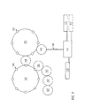
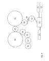
- FIG. 1 shows an exemplary blow molding machine with a heating device in the form of a heating wheel 101 and a blowing wheel 102.
- the heating wheel 101 comprises a plurality of heating elements in the form of heating chambers 103 for heating the preforms.
- the blowing wheel 102 comprises blowing stations 104, in which the heated preforms are blown into plastic containers, in particular stretch blown.
- the heated preforms are transferred via a transfer element 105 from the heating wheel 101 to the blowing wheel 102.
- Via a discharge element 106 and a plurality of transfer elements 107 the plastic containers produced can be transferred, for example, to a filling device and / or a labeling device.
- the preforms are transferred to the heating wheel 101 via a feed rail 108 and an inlet element 109, for example a sawtooth star.
- the preforms may in particular be different preforms from each other, which are taken, for example, from different chutes, for example, chutes 110, 111 and 112. Chute 112 is shown with a dashed line, which indicates that this chute is optional.
- the blow molding machine can also comprise more than three shots.
- the preforms can be brought into a predetermined order and then introduced in this predetermined order ("just-in-sequence") via the feed rail 108 and the inlet element 109 in the heating wheel 101.
- the blowing stations 104 of the blowing wheel 102 can be operated differently, in particular differently formed and / or controlled.
- operating parameters of at least two blowing stations 104 of the blowing wheel 102 may be different.
- the operating parameters may include, for example, the timing and / or size of a pre-blow pressure, a finish blow pressure, a pre-blow start (and / or end), a purge start, a temperature of the preform, a temperature of the wall of a blow mold, a temperature of a mold floor, a timing of a rinse pressure, a pressure curve during the pre-blowing, final blowing and rinsing, a temperature of the blow mold and / or a pressure pad pressure.
- the pressure pad pressure can be minimized in particular.
- the required mold clamping force can be adapted to the container to be produced. For smaller plastic bottles, for example, less pressure may be necessary, which may in particular save energy.
- Each blowing station 104 may be equipped with a separately controllable valve block.
- At least two heating chambers 103 of the heating wheel 101 can be operated differently, in particular differently formed and / or controlled.
- at least two heating chambers 103 may have different temperatures from each other.
- the heating wheel 101 may, for example, be a rotary furnace with heating pockets or heating chambers 103 arranged thereon.
- the heating wheel 101 may be a STIR furnace.
- STIR Selective-Transformed Infrared
- the preforms are introduced into heating pockets, which surround the preforms substantially completely except for the mouth section.
- a heating mandrel is introduced into the preform which at least partially consists of a functional ceramic which converts the infrared radiation introduced from the outside, which is transmitted through the preform, into radiation of a different wavelength and emits it back onto the preform.
- the preforms can be brought into a predetermined order, in particular such that predetermined preforms are assigned to predetermined heating chambers 103 and / or blowing stations 104.
- the exemplary blower of the FIG. 1 used to make four different plastic container types.
- four different preform types can be used for this purpose.
- clear preforms can be used to produce clear plastic containers, green preforms to produce green plastic containers, blue preforms to produce blue plastic bottles, and reddish preforms to produce reddish plastic bottles.
- Preforms of these four different preform types may be incorporated into the blow molding machine such that each of the preforms is associated with a heating chamber 103 and / or blow mold 104 which are operated to match the preform.
- heating chambers 103 and / or blowing stations 104 for clear preforms may be formed and / or controlled differently than heating chambers 103 and / or blowing stations 104 for green, blue, and / or reddish preforms.
- every fourth treatment station (blowing station 104 and / or heating chamber 103) along the blowing wheel 102 and / or the heating wheel 101 can process the same plastic bottle type.
- the preforms can not only differ in their color, the preforms can also different grammages, different geometric sizes, different Have wall thicknesses and / or different threads for different types of closure.
- the blowing stations 104 may in particular have different blow molds for different volumes, for example 0.33 liters, 0.5 liters, 0.75 liters or 1.0 liter.
- the blow molds can also have different geometries.
- the blow molding machine may include differently arranged curves that control functions of treatment units, such as heating chambers 103 and / or blowing stations 104.
- the curves may be arranged differently in the radial direction and / or in the vertical direction.
- a stroke of a bottom shape from one blowing station 104 to the next, an opening movement of a heating chamber 103 and / or blowing station 104 and / or a depth of immersion of a preform into a heating chamber 103 can be varied.
- the mold carrier of a heating chamber 103 and / or blow station 104 does not have to rise so far, which can save time and reduce wear / forces.
- a height of a conveyor may vary through the linear oven.
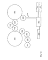
- FIG. 2 shows another exemplary blowing machine.
- the blow molding machine also has a blowing wheel 202 with a plurality of blow molding stations 204 and a discharge element 206 and a plurality of transfer elements 207.
- Preforms are introduced from piles 210, 211 and / or 212 by means of a sorting element 213 via a feed rail 208 and an inlet element 209 into a linear oven.
- the linear furnace comprises a transport element 214 for transporting the preforms through the linear furnace and a plurality of heating boxes 215 with vertically arranged elongate infrared radiators and a plurality of reflectors 216.
- the heating boxes can be designed and / or controlled such that different preforms are heated differently.
- microwave heating elements could also be provided. These effectively enable preforms to be heated selectively, in particular independently of each other.
- the exemplary blow molding machine may be a servo blower stretch blow machine.
- a plurality of different curves may be provided on the circumference of the blowing wheel 102, at which stretching rods are controlled by their curve followers (rollers) in their immersion position and / or speed.
- curve followers rollers
- several stretching speeds can be realized in a carousel of the blow molding machine.
- the curves may in this case be arranged radially offset from one another, so that, for example, the stretching rod of every second blowing station runs on an inner curve, and the other stretching rods run off on an outer curve.
- This principle can also be applied to a control of one or more shielding devices, for example shielding plates, in the linear furnace.
- a shielding plate can be operated by means of a servo, piezo or liner motor.
- a shielding plate serves as a barrier to thermal radiation and can be moved with a preform through the linear furnace.
- a timing of lifting and / or lowering of the shielding plate for the mouth region can be controlled.
- the regulation may be different for different preforms.
- the time in which a portion of a preform is protected by the shield plate can be controlled.
- the shielding plate can be removed before reaching the end of the linear furnace, so that a previously shielded portion of the preform, for example, an area directly below a support ring, is heated for a predetermined time.
- the receiving mandrel of the preform can also lift and / or lower.
- FIG. 3 shows details of an exemplary linear furnace for a blow molding machine. Via a feed rail 308 and an inlet element 309 preforms can be introduced into the linear furnace. By means of a transport device 314, the preforms can be moved through the linear furnace.
- a transport device 3114 By means of a transport device 314, the preforms can be moved through the linear furnace.
- FIG. 3 Several exemplary heating mandrels 317 with preforms are shown.
- FIG. 3 also shows a chain drive 319 for the rotation of the heating mandrels.
- a plurality of heating boxes 315 and reflectors 316 are shown.
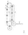
- FIG. 4 shows an alternative linear furnace for a blow molding machine.
- the preforms are introduced via a feed rail 408 and an inlet element 409 in the linear furnace.
- the heaters are not shown for clarity.
- the preforms can be moved via a transport element 414 through the linear furnace.
- One or more heater mandrels 417 may be rotated by a first chain drive 419 while one or more heater mandrels 418 may be rotated by a second chain drive 420.
- the two different chain drives 419 and 420 can rotate the heating mandrels 417, 418, in particular with mutually different speeds. As a result, depending on the heating mandrel, a different heating of a preform can be achieved.
- the chain drives 419 and 420 can be arranged at different heights.
- the chain drives 419 and 420 can also be arranged at different horizontal distance from the heating elements.
- Different sized gears of Schudornen 417, 418 can also cause a different rotational speed.
- a preform can be provided in the circumferential direction with a predetermined temperature profile. From each other different preforms can be provided in particular with different temperature profiles.
- the speeds of the respective chain drives 419 and 420 can be varied variably for profiling over a heating process of a preform.
- FIG. 5 shows another exemplary linear furnace for a blow molding machine.
- the transport element 514 which moves the preforms through the linear kiln, includes a deflector 521 which allows to selectively move preforms over a shorter transport path through the linear kiln.
- the shows FIG. 5 a first group of heaters 515 and reflectors 516; and a second group of heaters 515 and reflectors 516, with the deflector 521 disposed between the two groups.
- a preform introduced into the linear furnace via the feed rail 508 and inlet element 509 can now be selectively moved by the first and second group of heating boxes 515 or by the deflecting element 521 only by the first group of heating boxes 515.
- the heated preforms can be moved by means of a transfer element 505 to be given a blowing wheel.
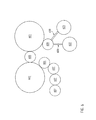
- FIG. 6 shows an exemplary blow molding machine, which is designed as injection blow molding machine with two injection modules 622 and 623.
- injection module 622 may injection mold a first grade or type of preforms
- injection module 623 may include a second grade of preforms that is different from the first grade of preforms.
- the first and second types of preforms may differ, for example, in geometry, color, wall thickness, composition and / or thread for a closure.
- the injection-molded preforms can be transferred to a heating wheel 601 via feed rails 608 and an inlet element 609.
- a transfer element 605 the heated preforms can be transferred to a blowing wheel 602, from which they can be transported via a discharge element 606 and transfer elements 607, for example to a filling device and / or a labeling device.
- FIG. 7 shows an example of a blow molding machine, in which the preforms are molded by means of a compression molding device 724 and transferred via a transfer element 725 to a heating wheel 701.
- the molding apparatus 724 may be operated to produce different preforms from each other.
- Via a transfer element 705, the preforms can be transferred from the heating wheel 701 to a blowing wheel 702 and then moved on via a discharge element 706 and transfer elements 707.
- the amount of plastic dispensed from an extruder can be controlled to produce different preforms from each other.
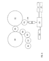
- FIG. 8 shows an exemplary blow molding machine, wherein in the feed rail 808, a sterilization element 826 is provided.
- Sterilization device 826 may treat the preforms with cleaning fluid, ionized air, and / or sterile air. It is possible to provide lances which dive at different depths (right up to the bottom of the preforms), which treat the preforms.
- the amount of sterilization medium can also vary with different preforms.
- the preforms can be immersed at different depths in immersion baths for coating and / or for sterilization.
- the sterilization device 826 may also perform a plasma sterilization or coating, in particular, which differently coats the preforms.
- the blowing machine shows the above-mentioned spouts 810, 811 and 812, a sorting element 813, an inlet element 809, a heating wheel 801, a transfer element 805, a blowing wheel 802, a discharge element 806 and transfer elements 807.
- FIG. 9 FIG. 11 shows an exemplary blow molding machine with a rotary sterilization 927 along the feed rail 908.
- the blow molding machine displays the above-mentioned chutes 910, 911 and 912, a sorting element 913, an inlet element 909, a heating wheel 901, a transfer element 905, a blowing wheel 902 Outlet element 906 and transfer elements 907.
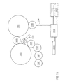
- FIG. 10 shows an exemplary blow molding machine wherein a rotary sterilizer 1029 is disposed between the heating wheel 1001 and the blowing wheel 1002. Via a discharge element 1028, the preforms are transferred to the sterilization device 1029 and passed through an inlet element 1030 in the blowing wheel 1002.
- FIG. 10 also shows the above mentioned spouts 1010, 1011, 1012, sorting element 1013, feed rail 1008, inlet element 1009, outlet element 1006 and transfer elements 1007.
- FIG. 11 shows an exemplary blow molding machine, wherein the blow molding machine comprises an in-label labeling module.
- the labeling device comprises a labeling unit 1131 and a label feed 1132.
- the labeling device With the labeling device, the plastic containers produced in the blowing wheel 1102 can be labeled in the blow molding machine.
- different labels can be successively introduced into blow molds, against which the expanding containers create during the blowing process.
- FIG. 11 also shows the spouts 1110, 1111 and 1112, a sorting element 1113, a feed rail 1108, an inlet element 1109, a heating wheel 1101, a transfer element 1105, a blowing wheel 1102, an outlet element 1106 and transfer elements 1107.
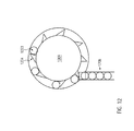
- FIG. 12 shows an exemplary inlet member 1209 via which, for example, preforms from a feed rail 1208 in a in FIG. 12 not shown heating wheel or a linear furnace can be introduced.
- the inlet element 1209 is in FIG. 12 is formed as a sawtooth star, which comprises a plurality of tooth elements 1234 for transporting preforms 1233.
- This in FIG. 12 shown inlet element 1209 is suitable for transporting preforms 1233 with the same mouth or neck diameter.
- FIG. 13 shows an exemplary inlet member 1309 for a blow molding machine, which is designed as a sawtooth star and allows the transport of preforms 1338 and 1333 with different neck diameters.
- teeth 1334 are provided which can transport preforms 1333 with a first neck diameter and teeth 1339 which can transport preforms 1338 with a second neck diameter.
- the second preforms 1338 can be fed via a second feed rail 1335, while the preforms 1333 are fed with a first neck diameter via a first feed rail 1308.
- Stoppers 1337 and 1336 respectively, may be provided for the feed rails 1308 and 1335, respectively, to interrupt the feeding of preforms.
- the stoppers 1337 and 1336 can introduce the preforms alternately into the inlet element 1309.
- the preforms could also be removed directly from a heating mandrel of a heating wheel or a linear furnace from the feed rails.
- this can be hampered by uneven alignment or positioning of the preforms in the feed rails.
- FIG. 13 also shows a counter element 1340 to the saw teeth 1339, which allows a more accurate positioning of the preforms 1338.
- blow molding machines described above can be combined with other machines of a bottling plant, in particular a filler and / or a labeling device, so be blocked.
- a filler and / or a labeling device so be blocked.
- block systems in the version stretch blow molder - labeling device - filler or in the execution stretch blow molder - filler - labeler are possible.
- the blow molding machines described above may further comprise an inspection device for automatically detecting preforms, in particular preforms introduced into the blow molding machine.
- an inspection device for automatically detecting preforms, in particular preforms introduced into the blow molding machine.
- the inspection device can be designed and / or configured such that a sensor of the inspection device recognizes a preform, in particular by recognizing at least one physical, chemical and / or geometric property of the preform, and the heating, sterilization and / or blowing process on the recognized preform adapts.
- This may include adjusting a treatment parameter of the heating, sterilization and / or blowing process. For example, a stroke of a tuyere, a stretching speed or an opening angle or spacing of the tuyeres could be adjusted.
- the blow molding machines described above may further include an allocator or distributor that associates a detected preform with a predetermined treatment unit.
- the inspection device may be configured and / or configured to perform a method including the steps of detecting a preform being inserted into the blow molding machine, determining whether the preform is suitable for processing in the blow molding machine, and determining that the preform is not suitable for processing in the blow molding machine, stopping the production of plastic containers and / or issuing a warning message.
- chutes for preforms there may be provided a plurality of chutes for preforms, wherein at least two of the chutes from each other different preforms, so different preform types have.
- a sorting device of the blow molding machine After a ganituren, automatically access one or more chutes or storage bins, especially if a specific production order (recipe) is selected and / or if a conclusion on one or more required preforms is possible by a detection of a blow mold.
- a change of molds for injection molding and a change of blow molding can be carried out synchronously, in particular by inputting a production order or by selecting at least one blow mold.
- the chemical composition of at least one preform can be controlled.
- buffer times for cooling can be controlled. This can be done in particular via a speed control of the spraying machine.
- an optimum ratio (breakeven point) between a proportion of an infrared absorber and a proportion of heating power can be determined with such a control, and the injection blow molding machine can be operated in this way.
- the infrared absorber concentration in different heating zones of a preform can also be varied, in particular based on a comparison of input values, for example measurements of a nine-fold pyrometer or a wall thickness measurement in the heating zones, with the values of an infrared absorption measurement.
Landscapes
- Engineering & Computer Science (AREA)
- Manufacturing & Machinery (AREA)
- Mechanical Engineering (AREA)
- Blow-Moulding Or Thermoforming Of Plastics Or The Like (AREA)
Applications Claiming Priority (1)
| Application Number | Priority Date | Filing Date | Title |
|---|---|---|---|
| DE102010003350A DE102010003350A1 (de) | 2010-03-26 | 2010-03-26 | Verfahren zum Herstellen von Kunststoffbehältern |
Publications (4)
| Publication Number | Publication Date |
|---|---|
| EP2368691A2 true EP2368691A2 (fr) | 2011-09-28 |
| EP2368691A3 EP2368691A3 (fr) | 2016-10-19 |
| EP2368691B1 EP2368691B1 (fr) | 2019-08-21 |
| EP2368691B2 EP2368691B2 (fr) | 2022-08-31 |
Family
ID=44202535
Family Applications (1)
| Application Number | Title | Priority Date | Filing Date |
|---|---|---|---|
| EP11151419.6A Active EP2368691B2 (fr) | 2010-03-26 | 2011-01-19 | Procédé de fabrication de récipients en matière synthétique et dispositif pour realiser le procéde |
Country Status (4)
| Country | Link |
|---|---|
| US (1) | US8591779B2 (fr) |
| EP (1) | EP2368691B2 (fr) |
| CN (1) | CN102205625B (fr) |
| DE (1) | DE102010003350A1 (fr) |
Cited By (4)
| Publication number | Priority date | Publication date | Assignee | Title |
|---|---|---|---|---|
| CN103950183A (zh) * | 2014-04-16 | 2014-07-30 | 苏州广型模具有限公司 | 一种模具吹塑机 |
| WO2017207425A1 (fr) * | 2016-05-31 | 2017-12-07 | Khs Gmbh | Ligne de fabrication et procédé pour faire fonctionner une ligne de fabrication |
| EP3481617B1 (fr) | 2016-07-11 | 2020-09-16 | Sidel Participations | Procede de fabrication de recipients en plastique par soufflage |
| EP3288742B1 (fr) | 2015-04-29 | 2022-04-06 | Sidel Participations | Procédé de commande d'un convoyeur de corps creux a travers une station de chauffage |
Families Citing this family (39)
| Publication number | Priority date | Publication date | Assignee | Title |
|---|---|---|---|---|
| US9108835B2 (en) * | 2008-05-20 | 2015-08-18 | Dai Nippon Printing Co., Ltd. | Beverage filling method and apparatus |
| DE102010018216B4 (de) * | 2010-04-23 | 2020-12-10 | Krones Aktiengesellschaft | Behältnisbehandlungsanlage mit änderbarer Beladung |
| DE102010053476A1 (de) | 2010-12-04 | 2012-06-06 | Krones Aktiengesellschaft | Fördervorrichtung für Behältnisse |
| DE102012102358A1 (de) * | 2012-03-20 | 2013-09-26 | Krones Ag | Verfahren zum Behandeln von Kunststoffbehältnissen mit Zeitreduzierung beim Synchronisieren von Anlagenteilen |
| DE102012102357A1 (de) * | 2012-03-20 | 2013-09-26 | Krones Ag | Preformtransport mit Auswurfmöglichkeit |
| DE102013100627A1 (de) * | 2013-01-22 | 2014-07-24 | Krones Aktiengesellschaft | Verfahren zum betreiben einer behälterbehandlungsanlage und behälterbehandlungsanlage |
| DE102013218399A1 (de) * | 2013-09-13 | 2015-03-19 | Krones Ag | Behälterbehandlungsanlage mit einem Ofen und einer Blasformvorrichtung mit Individual-Antrieb von Trägern für Preforms |
| DE102014100392A1 (de) | 2014-01-15 | 2015-07-16 | Krones Ag | Behälterbehandlungsmaschine zur Bedruckung von Behältern |
| DE102014103394B4 (de) * | 2014-03-13 | 2025-12-18 | Krones Ag | Vorrichtung und Verfahren zum Transportieren von Kunststoffvorformlingen |
| DE102015202660A1 (de) * | 2015-02-13 | 2016-08-18 | Krones Ag | Verfahren zum Umstellen einer Behälterbehandlungsanlage |
| CN109661623A (zh) | 2016-09-09 | 2019-04-19 | 宝洁公司 | 用于在单条生产线上同时生产不同产品的方法 |
| US10640249B2 (en) | 2016-09-09 | 2020-05-05 | The Procter & Gamble Company | Track system for creating finished products |
| CA3035965C (fr) | 2016-09-09 | 2022-01-11 | The Procter & Gamble Company | Systeme et procede de remplissage simultane de recipients avec differentes compositions fluides |
| US10996232B2 (en) | 2016-09-09 | 2021-05-04 | The Procter & Gamble Company | System and method for independently routing container-loaded vehicles to create different finished products |
| JP6810253B2 (ja) | 2016-09-09 | 2021-01-06 | ザ プロクター アンド ギャンブル カンパニーThe Procter & Gamble Company | 要求に基づいて製品を生産するためのシステム及び方法 |
| EP3509795B1 (fr) | 2016-09-09 | 2020-07-29 | The Procter and Gamble Company | Support à vide avec joint de jupe extensible |
| US11584628B2 (en) | 2016-09-09 | 2023-02-21 | The Procter & Gamble Company | System and method for independently routing vehicles and delivering containers and closures to unit operation systems |
| EP3509953A1 (fr) | 2016-09-09 | 2019-07-17 | The Procter and Gamble Company | Système et procédé de remplissage simultané de récipients de formes et/ou de tailles différentes |
| CA2995666A1 (fr) * | 2017-02-17 | 2018-08-17 | W. Amsler Equipment Inc. | Machine de moulage par etirage-gonflage permettant de produire differents articles a partir des memes preformes en un seul cycle |
| DE102017120201A1 (de) * | 2017-09-01 | 2019-03-21 | Krones Ag | Selbstlernende Blasmaschine mittels Bildauswertung |
| DE102017120762A1 (de) * | 2017-09-08 | 2019-03-14 | Krones Ag | Flexible Anlage zum Behandeln von Behältnissen |
| CN108508843B (zh) * | 2018-05-09 | 2020-03-24 | 浙江赛豪实业有限公司 | 一种模具的工况控制系统 |
| DE102018117849A1 (de) | 2018-07-24 | 2020-01-30 | Krones Ag | Verfahren und Vorrichtung zum Umformen von Kunststoffvorformlingen zu Kunststoffbehältnissen mit Vortemperierung von Blasformen |
| DE102020112382A1 (de) * | 2020-05-07 | 2021-11-11 | Krones Aktiengesellschaft | Maschinenblock zum Herstellen und Abfüllen von Flaschen und Verfahren zum Steuern des Maschinenblocks |
| DE102020113013A1 (de) | 2020-05-13 | 2021-11-18 | Volker Till | Blasform und -Verfahren zur Herstellung von Kunststoffflaschen unterschiedlicher Volumina |
| EP4161755B1 (fr) * | 2020-05-29 | 2025-07-23 | Husky Injection Molding Systems Ltd. | Procédés et appareil pour la commande de moulage |
| DE102020122471A1 (de) * | 2020-08-27 | 2022-03-03 | Krones Aktiengesellschaft | Verfahren und Vorrichtung zum Herstellen von Kunststoffvorformlingen und Kunststoffbehältnissen mit thermischen Vorformlingspeicher |
| DE102020123166A1 (de) * | 2020-09-04 | 2022-03-10 | Krones Aktiengesellschaft | Vorrichtung und Verfahren zum Erwärmen von Kunststoffvorformlingen mit ortaufgelöster Temperaturerfassung |
| DE102020123163A1 (de) * | 2020-09-04 | 2022-03-10 | Krones Aktiengesellschaft | Vorrichtung und Verfahren zum Erwärmen von Kunststoffvorformlingen mit ortaufgelöster Temperaturerfassung |
| DE102020127126A1 (de) | 2020-10-15 | 2022-04-21 | Khs Corpoplast Gmbh | Vorrichtung und Verfahren zum Herstellen von Behältern aus Vorformlingen aus thermoplastischem Material |
| US20240051214A1 (en) * | 2021-03-03 | 2024-02-15 | Husky Injection Molding Systems Ltd. | Plastic blank heating method and apparatus |
| DE102021105667A1 (de) * | 2021-03-09 | 2022-09-15 | Krones Aktiengesellschaft | Vorrichtung und Verfahren zum Umformen von Kunststoffvorformlingen zu Kunststoffbehältnissen mit zwei Vorformlingspeichern |
| DE102021119650A1 (de) | 2021-07-28 | 2023-02-02 | Khs Gmbh | Verfahren und Vorrichtung zum Herstellen von Behältern |
| DE102021121175A1 (de) * | 2021-08-16 | 2023-02-16 | Krones Aktiengesellschaft | Verfahren und Vorrichtung zum Überwachen des Herstellungsprozesses von Kunststoffbehältnissen |
| DE102021133791A1 (de) | 2021-12-20 | 2023-06-22 | Krones Aktiengesellschaft | Vorrichtung und Verfahren zum Herstellen von Kunststoffbehältnissen mit nicht kreisförmigen Querschnitten |
| DE102023113007A1 (de) * | 2023-05-17 | 2024-11-21 | Khs Gmbh | Behälterherstellungsmaschine und Verfahren zum Herstellen von Behältern aus Vorformlingen |
| DE102023129375A1 (de) * | 2023-10-25 | 2025-04-30 | Krones Aktiengesellschaft | Regelkreis für Behälterkühlung |
| DE102024101054A1 (de) | 2024-01-15 | 2025-07-17 | Krones Aktiengesellschaft | Vorrichtung und Verfahren zum Herstellen von Kunststoffbehältnissen mit Inspektion von Kunststoffvorformlingen |
| DE102024119160A1 (de) | 2024-07-05 | 2026-01-08 | Khs Gmbh | Behälterbehandlungsvorrichtung sowie Verfahren zum Absenken einer unzulässigen Konzentration eines flüchtigen Sterilisationsmittels |
Family Cites Families (39)
| Publication number | Priority date | Publication date | Assignee | Title |
|---|---|---|---|---|
| DE2339019A1 (de) † | 1973-08-01 | 1975-02-13 | 4 P Verpackungen Gmbh | Verfahren und vorrichtung zur herstellung von hohlkoerpern durch aufblasen von vorformlingen |
| DE2545131C3 (de) † | 1975-10-08 | 1980-08-21 | Gildemeister Corpoplast Gmbh, 2000 Hamburg | Vorrichtung zum Blasformen von Behältern, insbesondere von Flaschen |
| US4356907A (en) * | 1978-02-14 | 1982-11-02 | Aidlin Samuel S | Machine for distributing groups of workpieces to different destinations |
| WO1988009717A1 (fr) † | 1987-06-09 | 1988-12-15 | Toyo Seikan Kaisha, Ltd. | Procede de chauffe d'une bouteille ou d'une ebauche en matiere synthetique thermoplastique et procede de regulation de la temperature d'un organe chauffant |
| DE3831957C1 (fr) † | 1988-09-21 | 1989-12-28 | Bernd Dipl.-Ing. 7166 Sulzbach-Laufen De Hansen | |
| US5352402A (en) † | 1989-10-23 | 1994-10-04 | Nissei Asb Machine Co., Ltd. | Method and apparatus for manufacturing biaxially oriented, thermally stable, blown containers |
| CA2159169C (fr) * | 1994-09-27 | 2006-05-16 | Tony Salemi | Appareil de moulage par soufflage/injection de bouteilles de plastique et procede ameliore |
| US5591462A (en) | 1994-11-21 | 1997-01-07 | Pressco Technology, Inc. | Bottle inspection along molder transport path |
| AU6348196A (en) † | 1995-07-26 | 1997-02-26 | C.A. Greiner & Sohne Gesellschaft M.B.H. | Process and device for making containers |
| DE19615798A1 (de) * | 1996-04-20 | 1997-10-23 | Kautex Werke Gmbh | Vorrichtung zum Herstellen von Hohlkörpern aus thermoplastischem Kunststoff mittels Extrusions-Blasformen |
| DE19737697B4 (de) | 1997-08-29 | 2006-05-11 | Krones Ag | Spritzblasmaschine |
| DE19821105A1 (de) * | 1998-05-12 | 1999-11-18 | Krones Ag | Vorrichtung und Verfahren zur Herstellung von Kunststoffhohlkörpern |
| DE19843053A1 (de) * | 1998-09-19 | 2000-03-23 | Krupp Corpoplast Masch | Verfahren und Vorrichtung zur Steuerung eines Blasvorganges |
| US6113841A (en) * | 1998-11-17 | 2000-09-05 | Pechiney Plastic Packaging, Inc. | Multiple in-line parison control |
| DE19958435A1 (de) † | 1999-12-03 | 2001-06-07 | Krupp Corpoplast Maschb Gmbh | Verfahren und Vorrichtung zur Blasformung von Behältern |
| US6888103B2 (en) † | 2002-05-30 | 2005-05-03 | Ball Corporation | Preform preheater |
| US6773251B2 (en) * | 2002-07-11 | 2004-08-10 | Pechiney Emballage Flexible Europe | Segmented wheel disk for extrusion blowmolding apparatus |
| FR2848906B1 (fr) † | 2002-12-23 | 2006-08-18 | Sidel Sa | Procede et installation de fabrication d'un recipient en matiere plastique |
| AT412543B (de) † | 2003-11-07 | 2005-04-25 | Kosme Gmbh | Verfahren und vorrichtung zum erwärmen von hohlkörpern |
| EP1559529A3 (fr) † | 2004-02-02 | 2005-10-19 | The Procter & Gamble Company | Préformes en deux ou plusieurs matériaux et procédé pour leur obtention |
| US7534378B2 (en) * | 2004-03-03 | 2009-05-19 | Rexam Prescription Products Inc. | Plastic forming process monitoring and control |
| DE102006004940A1 (de) † | 2006-02-03 | 2007-08-23 | Sig Technology Ltd. | Verfahren und Vorrichtung zur Blasformung von Behältern |
| CN101516605B (zh) | 2006-08-11 | 2012-07-18 | 克罗内斯股份公司 | 注射吹塑机及用于拉伸吹塑塑料容器的工艺 |
| DE102006053193A1 (de) * | 2006-11-09 | 2008-05-15 | Krones Ag | Vorrichtung und Verfahren zur Herstellung von Kunststoffbehältern |
| FR2910329B1 (fr) * | 2006-12-20 | 2009-04-17 | Sidel Participations | Procede et dispositif de sterilisation de preformes |
| DE102007025527A1 (de) * | 2007-05-31 | 2008-12-04 | Khs Ag | Verfahren und Anlage zum Herstellen von Packmitteln |
| WO2008154503A2 (fr) † | 2007-06-08 | 2008-12-18 | Pressco Technology Inc. | Procédé et système d'irradiation et de traitement thermique à spécificité de longueur d'onde |
| DE102008034934B4 (de) † | 2007-10-23 | 2022-10-13 | Krones Aktiengesellschaft | Vorrichtung und Verfahren zum Herstellen von Behältnissen |
| DE102008010885A1 (de) † | 2008-02-25 | 2009-08-27 | Krones Ag | Vorrichtung und Verfahren zum Überwachen der Betriebsfähigkeit einer Behälterbehandlungsvorrichtung |
| DE102008012757A1 (de) † | 2008-03-05 | 2009-09-10 | Krones Ag | Vorrichtung zum Erzeugen von Kunststoffbehältnissen |
| GB0804266D0 (en) † | 2008-03-07 | 2008-04-16 | Univ Belfast | Thermoplastic preform method and apparatus |
| DE102008014215A1 (de) † | 2008-03-13 | 2009-09-17 | Krones Ag | Vorrichtung zum Erwärmen von Behältnissen |
| DE102008017759A1 (de) † | 2008-04-08 | 2009-10-15 | Krones Ag | Verfahren und Vorrichtung zum Herstellen von Kunststoffbehältnissen |
| EP2110224B1 (fr) † | 2008-04-17 | 2014-06-11 | Krones AG | Procédé et dispositif de fabrication de récipients en plastique avec surveillance de l'absorption par infrarouges |
| DE102008024108A1 (de) † | 2008-05-17 | 2009-11-19 | Krones Ag | Vorrichtung und Verfahren zum gesteuerten Erwärmen von Kunststoffbehältnissen |
| DE102008026043A1 (de) | 2008-05-30 | 2009-12-03 | Khs Ag | Verfahren und Vorrichtung zur kombinierten Herstellung und Abfüllung von Behältern aus Kunststoff |
| DE102008030866B4 (de) * | 2008-06-30 | 2017-05-18 | Krones Aktiengesellschaft | Blasvorrichtung, insbesondere für Behältnisse |
| IT1396854B1 (it) † | 2008-07-29 | 2012-12-20 | Sacmi Coop Mecc Imola Societa' Coop | Unita' di formatura di un impianto per il soffiaggio di contenitori di plastica, in particolare bottiglie |
| DE102008038143A1 (de) † | 2008-08-18 | 2010-02-25 | Krones Ag | Vorrichtung zum Sterilisieren von Kunststoffvorformlingen |
-
2010
- 2010-03-26 DE DE102010003350A patent/DE102010003350A1/de not_active Withdrawn
-
2011
- 2011-01-19 EP EP11151419.6A patent/EP2368691B2/fr active Active
- 2011-03-14 US US13/046,996 patent/US8591779B2/en not_active Expired - Fee Related
- 2011-03-25 CN CN201110079875.1A patent/CN102205625B/zh not_active Expired - Fee Related
Non-Patent Citations (1)
| Title |
|---|
| None |
Cited By (4)
| Publication number | Priority date | Publication date | Assignee | Title |
|---|---|---|---|---|
| CN103950183A (zh) * | 2014-04-16 | 2014-07-30 | 苏州广型模具有限公司 | 一种模具吹塑机 |
| EP3288742B1 (fr) | 2015-04-29 | 2022-04-06 | Sidel Participations | Procédé de commande d'un convoyeur de corps creux a travers une station de chauffage |
| WO2017207425A1 (fr) * | 2016-05-31 | 2017-12-07 | Khs Gmbh | Ligne de fabrication et procédé pour faire fonctionner une ligne de fabrication |
| EP3481617B1 (fr) | 2016-07-11 | 2020-09-16 | Sidel Participations | Procede de fabrication de recipients en plastique par soufflage |
Also Published As
| Publication number | Publication date |
|---|---|
| US20110236517A1 (en) | 2011-09-29 |
| CN102205625B (zh) | 2014-07-30 |
| EP2368691B2 (fr) | 2022-08-31 |
| DE102010003350A1 (de) | 2011-09-29 |
| EP2368691B1 (fr) | 2019-08-21 |
| EP2368691A3 (fr) | 2016-10-19 |
| CN102205625A (zh) | 2011-10-05 |
| US8591779B2 (en) | 2013-11-26 |
Similar Documents
| Publication | Publication Date | Title |
|---|---|---|
| EP2368691B1 (fr) | Procédé de fabrication de récipients en matière synthétique et dispositif pour réaliser le procédé | |
| EP2295226B1 (fr) | Installation de traitement de récipient et procédé de traitement de récipient pour le traitement de récipients pouvant être remplis avec un produit | |
| EP2439048B1 (fr) | Procédé de traitement d'au moins un récipient dans une installation de traitement de récipients | |
| EP2477937B1 (fr) | Dispositif de fabrication de récipients pour liquides | |
| EP2345524B1 (fr) | Appareil et méthode de mesure pour déterminer au moins une valeur de paramètre pour le fonctionnement d'une machine de moulage par soufflage | |
| EP2601107B1 (fr) | Procédé et dispositif d'exploitation d'une installation de manipulation de récipients avec sélection des paramètres de niveau supérieur | |
| EP2415677B1 (fr) | Procédé et dispositif de fonctionnement d'une installation pour le traitement des récipients avec sélection de paramètres commandée | |
| EP2460746B1 (fr) | Dispositif de transport pour récipients | |
| EP2188108B2 (fr) | Procédé de moulage par soufflage de récipients | |
| EP2447038A2 (fr) | Souffleuse en construction modulaire | |
| EP2709819A1 (fr) | Procédé et dispositif pour nettoyer et/ou désinfecter un dispositif pour la fabrication de contenants remplis d'une matière de remplissage liquide | |
| EP3678837B1 (fr) | Installation flexible de traitement de récipients | |
| EP2414146A1 (fr) | Équipement de formage d'ébauches en matière plastique doté d'un dispositif de chauffage | |
| CN104936761A (zh) | 用于运行容器处理设备的方法和容器处理设备 | |
| EP2319770B1 (fr) | Dispositif et procédé destinés à l'étiquetage de récipients remplis | |
| DE102005015565A1 (de) | Anlage zum Herstellen und Bearbeiten von Behältern | |
| DE102012101915A9 (de) | Heizvorrichtung und Verfahren zum Temperieren von Vorformlingen | |
| WO2005023518A1 (fr) | Procédé et dispositif de maniement de pièces | |
| EP4494842A1 (fr) | Installation de traitement de récipients et procédé de fabrication et de traitement d'une préforme | |
| EP3986693B1 (fr) | Appareil de moule de soufflage et procédé de moulage par soufflage pour la production de bouteilles en plastique de différents volumes | |
| WO2019115327A1 (fr) | Dispositif et procédé destinés au formage de préformes en plastique en récipients en plastique, comprenant une étanchéification de la zone d'embouchure des récipients en plastique | |
| DE102024112557A1 (de) | Behälterbehandlungsanlage sowie Verfahren zum Betrieb |
Legal Events
| Date | Code | Title | Description |
|---|---|---|---|
| PUAI | Public reference made under article 153(3) epc to a published international application that has entered the european phase |
Free format text: ORIGINAL CODE: 0009012 |
|
| AK | Designated contracting states |
Kind code of ref document: A2 Designated state(s): AL AT BE BG CH CY CZ DE DK EE ES FI FR GB GR HR HU IE IS IT LI LT LU LV MC MK MT NL NO PL PT RO RS SE SI SK SM TR |
|
| AX | Request for extension of the european patent |
Extension state: BA ME |
|
| RIN1 | Information on inventor provided before grant (corrected) |
Inventor name: WINZINGER, FRANK Inventor name: SENN, KONRAD Inventor name: AUST, ROBERT |
|
| PUAL | Search report despatched |
Free format text: ORIGINAL CODE: 0009013 |
|
| AK | Designated contracting states |
Kind code of ref document: A3 Designated state(s): AL AT BE BG CH CY CZ DE DK EE ES FI FR GB GR HR HU IE IS IT LI LT LU LV MC MK MT NL NO PL PT RO RS SE SI SK SM TR |
|
| AX | Request for extension of the european patent |
Extension state: BA ME |
|
| RIC1 | Information provided on ipc code assigned before grant |
Ipc: B29C 49/00 20060101ALN20160912BHEP Ipc: B29K 67/00 20060101ALN20160912BHEP Ipc: B29L 31/00 20060101ALN20160912BHEP Ipc: B29C 49/42 20060101ALI20160912BHEP Ipc: B29C 49/06 20060101ALN20160912BHEP Ipc: B29C 49/64 20060101ALN20160912BHEP Ipc: B29C 49/28 20060101ALN20160912BHEP Ipc: B29C 49/36 20060101AFI20160912BHEP |
|
| STAA | Information on the status of an ep patent application or granted ep patent |
Free format text: STATUS: REQUEST FOR EXAMINATION WAS MADE |
|
| 17P | Request for examination filed |
Effective date: 20170412 |
|
| RBV | Designated contracting states (corrected) |
Designated state(s): AL AT BE BG CH CY CZ DE DK EE ES FI FR GB GR HR HU IE IS IT LI LT LU LV MC MK MT NL NO PL PT RO RS SE SI SK SM TR |
|
| STAA | Information on the status of an ep patent application or granted ep patent |
Free format text: STATUS: EXAMINATION IS IN PROGRESS |
|
| 17Q | First examination report despatched |
Effective date: 20180720 |
|
| GRAP | Despatch of communication of intention to grant a patent |
Free format text: ORIGINAL CODE: EPIDOSNIGR1 |
|
| STAA | Information on the status of an ep patent application or granted ep patent |
Free format text: STATUS: GRANT OF PATENT IS INTENDED |
|
| INTG | Intention to grant announced |
Effective date: 20190402 |
|
| GRAS | Grant fee paid |
Free format text: ORIGINAL CODE: EPIDOSNIGR3 |
|
| GRAA | (expected) grant |
Free format text: ORIGINAL CODE: 0009210 |
|
| STAA | Information on the status of an ep patent application or granted ep patent |
Free format text: STATUS: THE PATENT HAS BEEN GRANTED |
|
| AK | Designated contracting states |
Kind code of ref document: B1 Designated state(s): AL AT BE BG CH CY CZ DE DK EE ES FI FR GB GR HR HU IE IS IT LI LT LU LV MC MK MT NL NO PL PT RO RS SE SI SK SM TR |
|
| REG | Reference to a national code |
Ref country code: GB Ref legal event code: FG4D Free format text: NOT ENGLISH |
|
| REG | Reference to a national code |
Ref country code: CH Ref legal event code: EP |
|
| REG | Reference to a national code |
Ref country code: DE Ref legal event code: R096 Ref document number: 502011016014 Country of ref document: DE |
|
| REG | Reference to a national code |
Ref country code: AT Ref legal event code: REF Ref document number: 1169217 Country of ref document: AT Kind code of ref document: T Effective date: 20190915 |
|
| REG | Reference to a national code |
Ref country code: IE Ref legal event code: FG4D Free format text: LANGUAGE OF EP DOCUMENT: GERMAN |
|
| REG | Reference to a national code |
Ref country code: LT Ref legal event code: MG4D |
|
| REG | Reference to a national code |
Ref country code: NL Ref legal event code: MP Effective date: 20190821 |
|
| PG25 | Lapsed in a contracting state [announced via postgrant information from national office to epo] |
Ref country code: PT Free format text: LAPSE BECAUSE OF FAILURE TO SUBMIT A TRANSLATION OF THE DESCRIPTION OR TO PAY THE FEE WITHIN THE PRESCRIBED TIME-LIMIT Effective date: 20191223 Ref country code: BG Free format text: LAPSE BECAUSE OF FAILURE TO SUBMIT A TRANSLATION OF THE DESCRIPTION OR TO PAY THE FEE WITHIN THE PRESCRIBED TIME-LIMIT Effective date: 20191121 Ref country code: SE Free format text: LAPSE BECAUSE OF FAILURE TO SUBMIT A TRANSLATION OF THE DESCRIPTION OR TO PAY THE FEE WITHIN THE PRESCRIBED TIME-LIMIT Effective date: 20190821 Ref country code: NL Free format text: LAPSE BECAUSE OF FAILURE TO SUBMIT A TRANSLATION OF THE DESCRIPTION OR TO PAY THE FEE WITHIN THE PRESCRIBED TIME-LIMIT Effective date: 20190821 Ref country code: HR Free format text: LAPSE BECAUSE OF FAILURE TO SUBMIT A TRANSLATION OF THE DESCRIPTION OR TO PAY THE FEE WITHIN THE PRESCRIBED TIME-LIMIT Effective date: 20190821 Ref country code: LT Free format text: LAPSE BECAUSE OF FAILURE TO SUBMIT A TRANSLATION OF THE DESCRIPTION OR TO PAY THE FEE WITHIN THE PRESCRIBED TIME-LIMIT Effective date: 20190821 Ref country code: FI Free format text: LAPSE BECAUSE OF FAILURE TO SUBMIT A TRANSLATION OF THE DESCRIPTION OR TO PAY THE FEE WITHIN THE PRESCRIBED TIME-LIMIT Effective date: 20190821 Ref country code: NO Free format text: LAPSE BECAUSE OF FAILURE TO SUBMIT A TRANSLATION OF THE DESCRIPTION OR TO PAY THE FEE WITHIN THE PRESCRIBED TIME-LIMIT Effective date: 20191121 |
|
| PG25 | Lapsed in a contracting state [announced via postgrant information from national office to epo] |
Ref country code: AL Free format text: LAPSE BECAUSE OF FAILURE TO SUBMIT A TRANSLATION OF THE DESCRIPTION OR TO PAY THE FEE WITHIN THE PRESCRIBED TIME-LIMIT Effective date: 20190821 Ref country code: ES Free format text: LAPSE BECAUSE OF FAILURE TO SUBMIT A TRANSLATION OF THE DESCRIPTION OR TO PAY THE FEE WITHIN THE PRESCRIBED TIME-LIMIT Effective date: 20190821 Ref country code: GR Free format text: LAPSE BECAUSE OF FAILURE TO SUBMIT A TRANSLATION OF THE DESCRIPTION OR TO PAY THE FEE WITHIN THE PRESCRIBED TIME-LIMIT Effective date: 20191122 Ref country code: IS Free format text: LAPSE BECAUSE OF FAILURE TO SUBMIT A TRANSLATION OF THE DESCRIPTION OR TO PAY THE FEE WITHIN THE PRESCRIBED TIME-LIMIT Effective date: 20191221 Ref country code: RS Free format text: LAPSE BECAUSE OF FAILURE TO SUBMIT A TRANSLATION OF THE DESCRIPTION OR TO PAY THE FEE WITHIN THE PRESCRIBED TIME-LIMIT Effective date: 20190821 Ref country code: LV Free format text: LAPSE BECAUSE OF FAILURE TO SUBMIT A TRANSLATION OF THE DESCRIPTION OR TO PAY THE FEE WITHIN THE PRESCRIBED TIME-LIMIT Effective date: 20190821 |
|
| PG25 | Lapsed in a contracting state [announced via postgrant information from national office to epo] |
Ref country code: TR Free format text: LAPSE BECAUSE OF FAILURE TO SUBMIT A TRANSLATION OF THE DESCRIPTION OR TO PAY THE FEE WITHIN THE PRESCRIBED TIME-LIMIT Effective date: 20190821 |
|
| PG25 | Lapsed in a contracting state [announced via postgrant information from national office to epo] |
Ref country code: RO Free format text: LAPSE BECAUSE OF FAILURE TO SUBMIT A TRANSLATION OF THE DESCRIPTION OR TO PAY THE FEE WITHIN THE PRESCRIBED TIME-LIMIT Effective date: 20190821 Ref country code: EE Free format text: LAPSE BECAUSE OF FAILURE TO SUBMIT A TRANSLATION OF THE DESCRIPTION OR TO PAY THE FEE WITHIN THE PRESCRIBED TIME-LIMIT Effective date: 20190821 Ref country code: PL Free format text: LAPSE BECAUSE OF FAILURE TO SUBMIT A TRANSLATION OF THE DESCRIPTION OR TO PAY THE FEE WITHIN THE PRESCRIBED TIME-LIMIT Effective date: 20190821 Ref country code: DK Free format text: LAPSE BECAUSE OF FAILURE TO SUBMIT A TRANSLATION OF THE DESCRIPTION OR TO PAY THE FEE WITHIN THE PRESCRIBED TIME-LIMIT Effective date: 20190821 |
|
| PG25 | Lapsed in a contracting state [announced via postgrant information from national office to epo] |
Ref country code: IS Free format text: LAPSE BECAUSE OF FAILURE TO SUBMIT A TRANSLATION OF THE DESCRIPTION OR TO PAY THE FEE WITHIN THE PRESCRIBED TIME-LIMIT Effective date: 20200224 Ref country code: SK Free format text: LAPSE BECAUSE OF FAILURE TO SUBMIT A TRANSLATION OF THE DESCRIPTION OR TO PAY THE FEE WITHIN THE PRESCRIBED TIME-LIMIT Effective date: 20190821 Ref country code: SM Free format text: LAPSE BECAUSE OF FAILURE TO SUBMIT A TRANSLATION OF THE DESCRIPTION OR TO PAY THE FEE WITHIN THE PRESCRIBED TIME-LIMIT Effective date: 20190821 Ref country code: CZ Free format text: LAPSE BECAUSE OF FAILURE TO SUBMIT A TRANSLATION OF THE DESCRIPTION OR TO PAY THE FEE WITHIN THE PRESCRIBED TIME-LIMIT Effective date: 20190821 |
|
| REG | Reference to a national code |
Ref country code: DE Ref legal event code: R026 Ref document number: 502011016014 Country of ref document: DE |
|
| PLBI | Opposition filed |
Free format text: ORIGINAL CODE: 0009260 |
|
| PLAX | Notice of opposition and request to file observation + time limit sent |
Free format text: ORIGINAL CODE: EPIDOSNOBS2 |
|
| 26 | Opposition filed |
Opponent name: SIDEL PARTICIPATIONS S.A.S. Effective date: 20200602 |
|
| PG2D | Information on lapse in contracting state deleted |
Ref country code: IS |
|
| PG25 | Lapsed in a contracting state [announced via postgrant information from national office to epo] |
Ref country code: MC Free format text: LAPSE BECAUSE OF FAILURE TO SUBMIT A TRANSLATION OF THE DESCRIPTION OR TO PAY THE FEE WITHIN THE PRESCRIBED TIME-LIMIT Effective date: 20190821 Ref country code: SI Free format text: LAPSE BECAUSE OF FAILURE TO SUBMIT A TRANSLATION OF THE DESCRIPTION OR TO PAY THE FEE WITHIN THE PRESCRIBED TIME-LIMIT Effective date: 20190821 |
|
| REG | Reference to a national code |
Ref country code: CH Ref legal event code: PL |
|
| GBPC | Gb: european patent ceased through non-payment of renewal fee |
Effective date: 20200119 |
|
| REG | Reference to a national code |
Ref country code: BE Ref legal event code: MM Effective date: 20200131 |
|
| PLBB | Reply of patent proprietor to notice(s) of opposition received |
Free format text: ORIGINAL CODE: EPIDOSNOBS3 |
|
| PG25 | Lapsed in a contracting state [announced via postgrant information from national office to epo] |
Ref country code: GB Free format text: LAPSE BECAUSE OF NON-PAYMENT OF DUE FEES Effective date: 20200119 Ref country code: LU Free format text: LAPSE BECAUSE OF NON-PAYMENT OF DUE FEES Effective date: 20200119 |
|
| PG25 | Lapsed in a contracting state [announced via postgrant information from national office to epo] |
Ref country code: LI Free format text: LAPSE BECAUSE OF NON-PAYMENT OF DUE FEES Effective date: 20200131 Ref country code: CH Free format text: LAPSE BECAUSE OF NON-PAYMENT OF DUE FEES Effective date: 20200131 Ref country code: BE Free format text: LAPSE BECAUSE OF NON-PAYMENT OF DUE FEES Effective date: 20200131 |
|
| PG25 | Lapsed in a contracting state [announced via postgrant information from national office to epo] |
Ref country code: IE Free format text: LAPSE BECAUSE OF NON-PAYMENT OF DUE FEES Effective date: 20200119 |
|
| REG | Reference to a national code |
Ref country code: AT Ref legal event code: MM01 Ref document number: 1169217 Country of ref document: AT Kind code of ref document: T Effective date: 20200119 |
|
| PG25 | Lapsed in a contracting state [announced via postgrant information from national office to epo] |
Ref country code: AT Free format text: LAPSE BECAUSE OF NON-PAYMENT OF DUE FEES Effective date: 20200119 |
|
| PG25 | Lapsed in a contracting state [announced via postgrant information from national office to epo] |
Ref country code: MT Free format text: LAPSE BECAUSE OF FAILURE TO SUBMIT A TRANSLATION OF THE DESCRIPTION OR TO PAY THE FEE WITHIN THE PRESCRIBED TIME-LIMIT Effective date: 20190821 Ref country code: CY Free format text: LAPSE BECAUSE OF FAILURE TO SUBMIT A TRANSLATION OF THE DESCRIPTION OR TO PAY THE FEE WITHIN THE PRESCRIBED TIME-LIMIT Effective date: 20190821 |
|
| PG25 | Lapsed in a contracting state [announced via postgrant information from national office to epo] |
Ref country code: MK Free format text: LAPSE BECAUSE OF FAILURE TO SUBMIT A TRANSLATION OF THE DESCRIPTION OR TO PAY THE FEE WITHIN THE PRESCRIBED TIME-LIMIT Effective date: 20190821 |
|
| PUAH | Patent maintained in amended form |
Free format text: ORIGINAL CODE: 0009272 |
|
| STAA | Information on the status of an ep patent application or granted ep patent |
Free format text: STATUS: PATENT MAINTAINED AS AMENDED |
|
| 27A | Patent maintained in amended form |
Effective date: 20220831 |
|
| AK | Designated contracting states |
Kind code of ref document: B2 Designated state(s): AL AT BE BG CH CY CZ DE DK EE ES FI FR GB GR HR HU IE IS IT LI LT LU LV MC MK MT NL NO PL PT RO RS SE SI SK SM TR |
|
| REG | Reference to a national code |
Ref country code: DE Ref legal event code: R102 Ref document number: 502011016014 Country of ref document: DE |
|
| P01 | Opt-out of the competence of the unified patent court (upc) registered |
Effective date: 20230523 |
|
| PGFP | Annual fee paid to national office [announced via postgrant information from national office to epo] |
Ref country code: FR Payment date: 20241209 Year of fee payment: 15 |
|
| PGFP | Annual fee paid to national office [announced via postgrant information from national office to epo] |
Ref country code: DE Payment date: 20241203 Year of fee payment: 15 |
|
| PGFP | Annual fee paid to national office [announced via postgrant information from national office to epo] |
Ref country code: IT Payment date: 20241210 Year of fee payment: 15 |