EP2368710A1 - Procédé de changement de plaques d'impression dans des presses rotatives dotées de plusieurs unités d'impression - Google Patents
Procédé de changement de plaques d'impression dans des presses rotatives dotées de plusieurs unités d'impression Download PDFInfo
- Publication number
- EP2368710A1 EP2368710A1 EP11155520A EP11155520A EP2368710A1 EP 2368710 A1 EP2368710 A1 EP 2368710A1 EP 11155520 A EP11155520 A EP 11155520A EP 11155520 A EP11155520 A EP 11155520A EP 2368710 A1 EP2368710 A1 EP 2368710A1
- Authority
- EP
- European Patent Office
- Prior art keywords
- plate
- printing
- cylinder
- printing unit
- plates
- Prior art date
- Legal status (The legal status is an assumption and is not a legal conclusion. Google has not performed a legal analysis and makes no representation as to the accuracy of the status listed.)
- Granted
Links
Images

Classifications
-
- B—PERFORMING OPERATIONS; TRANSPORTING
- B41—PRINTING; LINING MACHINES; TYPEWRITERS; STAMPS
- B41F—PRINTING MACHINES OR PRESSES
- B41F27/00—Devices for attaching printing elements or formes to supports
- B41F27/12—Devices for attaching printing elements or formes to supports for attaching flexible printing formes
- B41F27/1206—Feeding to or removing from the forme cylinder
-
- B—PERFORMING OPERATIONS; TRANSPORTING
- B41—PRINTING; LINING MACHINES; TYPEWRITERS; STAMPS
- B41F—PRINTING MACHINES OR PRESSES
- B41F13/00—Common details of rotary presses or machines
- B41F13/08—Cylinders
- B41F13/24—Cylinder-tripping devices; Cylinder-impression adjustments
-
- B—PERFORMING OPERATIONS; TRANSPORTING
- B41—PRINTING; LINING MACHINES; TYPEWRITERS; STAMPS
- B41F—PRINTING MACHINES OR PRESSES
- B41F33/00—Indicating, counting, warning, control or safety devices
- B41F33/04—Tripping devices or stop-motions
- B41F33/12—Tripping devices or stop-motions for starting or stopping the machine as a whole
-
- B—PERFORMING OPERATIONS; TRANSPORTING
- B41—PRINTING; LINING MACHINES; TYPEWRITERS; STAMPS
- B41F—PRINTING MACHINES OR PRESSES
- B41F33/00—Indicating, counting, warning, control or safety devices
- B41F33/04—Tripping devices or stop-motions
- B41F33/14—Automatic control of tripping devices by feelers, photoelectric devices, pneumatic devices, or other detectors
-
- B—PERFORMING OPERATIONS; TRANSPORTING
- B41—PRINTING; LINING MACHINES; TYPEWRITERS; STAMPS
- B41P—INDEXING SCHEME RELATING TO PRINTING, LINING MACHINES, TYPEWRITERS, AND TO STAMPS
- B41P2227/00—Mounting or handling printing plates; Forming printing surfaces in situ
- B41P2227/60—Devices for transferring printing plates
- B41P2227/62—Devices for introducing printing plates
-
- B—PERFORMING OPERATIONS; TRANSPORTING
- B41—PRINTING; LINING MACHINES; TYPEWRITERS; STAMPS
- B41P—INDEXING SCHEME RELATING TO PRINTING, LINING MACHINES, TYPEWRITERS, AND TO STAMPS
- B41P2227/00—Mounting or handling printing plates; Forming printing surfaces in situ
- B41P2227/60—Devices for transferring printing plates
- B41P2227/63—Devices for removing printing plates
Definitions
- the present invention relates to a method for changing printing plates in rotary printing machines with multiple printing units. These may be sheet or web presses.
- Disturbances can now occur in the course of a plate changing process in that, for example, the printing plate is tilted in a printing unit as it is being conveyed out, the electromechanically actuated clamping strip does not open, the sensors for detecting the plate edge or the plate end report errors, etc. Therefore, operating modes have also already been developed. to complete the plate changing process as effectively as possible in such a disturbance. For this the beats EP 1 348 551 B1 before, after detecting the fault, disengage the plate cylinder in the faulty printing unit once from the drive and completely complete the change process for the other printing units, before then the fault is eliminated then the plate is changed in the faulty printing unit.
- the respective blanket cylinder is moved at a slightly higher peripheral speed than the associated plate cylinder. This has the consequence that the pressure plate, if it comes during the ejection movement with the blanket cylinder in contact, is not compressed, but at best "pulled straight" by the slightly higher peripheral speed of the blanket. In this way, she always safely finds her way back to the holding position on the protection of the printing unit.
- the same measure can also be taken if, before or after the elimination of the disturbance, the plate cylinders move the printing plates out of the no or no longer disturbed printing units, as well in plate change processes in which the removal is always carried out by the plate cylinder in the parked and uncoupled from the main drive of the machine state.
- the plate cylinders are disengaged in the non-disturbed printing units, the respective blanket cylinder in these printing units with a slightly higher speed than the plate cylinders are moved while continuing the ejecting operation and at the same time as described in claim 6 and the plate cylinder of the defective printing unit is disengaged and there the plate cylinder is moved to the position in which the disorder can be eliminated, for example, the position in which Screws of the plate clamping rail can be opened manually, or moves the plate cylinder of the faulty printing unit in a reference position.
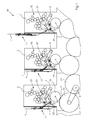
- the FIG. 1 shows a Bogenoffsetrotationsdruckmaschine 30 with multiple printing units in a row construction, of which three printing units 1, 2, 3 are shown.
- Each of the printing units 1, 2, 3 has an inking unit 25, which transfers the ink to a spanned in printing operation on a plate cylinder 23 printing plate with the printed image.
- the printed image is transferred via a blanket cylinder 22 to a substrate 31, which is printed in the nip between blanket cylinder 22 and impression cylinder 26.
- the printing materials 31 are moved by means of transport cylinders 24.
- the impression cylinder 26 and transport cylinder 24 and the blanket cylinder 22 are mechanically connected to each other via a gear train and are driven by a main drive motor 5.
- the plate cylinder 23 in the printing units 1, 2, 3 driven by the here schematically drawn couplings 29 between the plate cylinders 23 and the blanket cylinders 22 are closed. If a print job change is pending, so new plates 6 must be mounted with the new color separations on the plate cylinders 23 and the old printing plates 7 are removed.
- the printing units 1, 2, 3 each have a plate changer 17 on the left side, which accommodates the old printing plate 7 and provides the new printing plate 6.
- the plate cylinders 23 can be disengaged and driven independently of the other cylinders 22, 24, 26 by means of their own drive motor 4 (auxiliary drive).
- FIG. 1 are the three printing units 1, 2, 3 in different positions during the plate change.
- printing unit 3 the plate trailing edge of the old printing plate 7 is just released, so that the old printing plate 7 can be conveyed out.
- printing unit 2 the old printing plate 7 was pushed by the backward plate cylinder 23 out in the disc changer 17.
- the old printing plate 7 has been completely pushed out of the printing unit 1 and in the disc changer 17 in a position in which the new plate can be clamped.
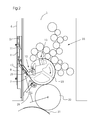
- FIG. 2 is fragmentary, the printing unit 3 shown.
- the plate changer 17 has a lower plate guide element 8 and an upper plate guide element 9.
- a pivotable guide element 10 which is intended to remove the old pressure plate 7 via rollers from the plate cylinder 23.
- the plate changer 17 itself is mechanically stored so that it can be easily lifted and lowered again by the operating personnel by gas pressure springs or other aids.
- the disc changer 17 also carries a sensor 27, with the correct removal of the old plate 7 can be determined.
- On the outside of the disk changer 17 are guide elements with rollers in which the new pressure plate 6 is mounted receptive.
- the guide element 10 is pivoted toward the plate cylinder 23, so that the old pressure plate 7 on the rollers of the guide element 10 out can slide.
- the plate clamping device is opened at the trailing edge 12 on the plate cylinder 23, so that the old pressure plate 7 solves due to their rigidity from the plate cylinder 23 and can slide on the rollers of the pivotable guide element 10 out.
- the feeding out of the old pressure plate 7 is usually done when employed on the plate cylinder 23 blanket cylinder 22, so that the old pressure plate 7 is conveyed in the gap between the blanket cylinder 22 and plate cylinder 23 in the direction of the pivotable guide element 10.
- On the pivotable guide element 10, a further sensor 28 is mounted on the pivotable guide element 10.
- the machine control is informed whether the old pressure plate 7 has actually detached from the plate cylinder 23 and is not tilted for any reason.
- blanket cylinder 22 and plate cylinder 23 are mechanically coupled together and are driven by the continuous gear train on the main drive motor 5.
- the plate cylinder 23 moves in the direction of arrow, so that the old printing plate 7 is required in the disc changer 17.
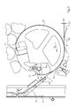
- FIG. 3 shows an enlargement of the area around the plate cylinder 23 in the printing unit 3.
- FIG. 3 is to recognize the open plate clamping device 12 for the plate trailing edge, which allows the feeding out of the old printing plate 7.
- the plate clamping device 13 for the front edge on the plate cylinder 23 remains closed until the old pressure plate 7 has passed the gap between blanket cylinder 22 and plate cylinder 23.
- a pressing element 16 can be seen, which is later required when clamping the new printing plate 6.
- the old pressure plate 7 has been conveyed out of the plate cylinder 23, so that only the plate clamping device for the front edge 13 has to be opened.
- This end position of the pushed out old pressure plate 7 can also be detected by the sensor 27.
- the control computer opens the mechanical clutch 29 between plate cylinder 23 and blanket cylinder 22 and disconnects the two cylinders from each other.
- the clutch 29 can be opened already when the clamping device 12 the Blanket cylinder 22 has happened.
- the plate cylinder 23 is driven only via its associated separate drive motor 4.
- the plate cylinder 23 is then driven independently of the other cylinders 22, 24, 26 in the gear train.
- This plate clamping device 11 is designed so that the old pressure plate 7 can be pushed only in one direction upwards, so that the old pressure plate 7 can not slip back again. This reliably prevents unintentional slipping back in the direction of the plate cylinder 23.
- This plate clamping device 11 consists of a pinch roller 11.1, a clamping surface 11.2 and a guide track 11.3.
- the pinch roller 11.1 When feeding out the old pressure plate 7, the pinch roller 11.1 is pushed along the guideway 11.3 upwards. By its own weight or additional support in the form of a spring force, the roller 11.3 clamps the old pressure plate 7 relative to the clamping surface 11.2, so that slipping back is reliably prevented. As a result, the old pressure plate 7 can only move upwards.
- the control of the printing press changes to a mode for rectifying this fault and, once, stops the main drive 5 of the machine.
- the faulty printing unit 3 goes to "pressure from”, ie the blanket cylinder 22 is turned off by the plate cylinder 23, ie shifted by not shown pneumatic actuated eccentric by ⁇ Z of about 0.5 millimeters in the dot-dash line position ( Fig. 3 ).
- the coupling 29 opens and thus interrupts the power flow between the plate cylinder 23 and the main drive 5 in the printing unit third
- the fault may be, for example, that the clamping rail of the plate clamping device 12 has not opened for the trailing edge of the pressure plate 7, which detected by the sensor 28 and reported by a corresponding signal of the control of the machine.
- the plate cylinder 23 is moved by the drive motor 4 of its auxiliary drive in the position in which the screws of the clamping rail can be opened manually. This is done by the operator and thus suppresses the printing unit.
- the motor 4 of the auxiliary drive rotates the coupled plate cylinder 23 in the currently suppressed printing unit until the end of the plate 7 has reached the sensor 28.
- the positioning movement of the plate cylinder takes place in the forward direction, while the blanket cylinder 22 either stands still or rotates backwards. In this way, it is ensured that the loose trailing edge of the plate 7 can nowhere abut in the printing unit and can thereby bend.
- the main drive 5 rotates in a position in which the printing units 1 and 2 are synchronous to the position occupied by the plate cylinder 23 in the currently suppressed printing unit 3. There, the clutch 29 between plate cylinder 23 and main drive 5 is still open.
- the plate cylinder 23 is now rotated by the drive motor 4 of its auxiliary drive backwards, at the same time the main drive 5 rotates the machine and thus the blanket cylinder 22 in the printing unit 1 also backwards, but with a slightly increased speed.
- the difference ⁇ V between the peripheral speed V PL of the plate cylinder 23 and the peripheral speed V GZ of the blanket cylinder 22 is between 0.5 and 10% of the amount of the speed.
- the plate 7 is then ejected in the printing unit 1 in the disc changer 17 and the drive 4 stops for the currently suppressed printing unit 3 and the operator can remove the ejected plate.
- the operator can create the side mounted on the disc changer 17 new printing plate 6 in all printing on the register pins in the disc clamping device 13 for the leading edge of the plate 6 or the system can be done in an alternative variant by an automatic feed of the plate.
- the new printing plates 6 can be retracted synchronously in all printing units together.
- all the plate cylinder as described above by opening the mechanical clutches 29 separated from the other cylinders 22, 24, 26 in the gear train and also the Beiwolf between the plate cylinders 23 and the blanket cylinders 22 in the non-disturbed printing units 1 and 2 in the position "pressure from "open. If the new pressure plate 6 is correctly applied, the plate clamping device is closed at the leading edge 13 and the control computer triggers the disc tray. In this case, all the plate cylinder 23 rotate in the printing units 1, 2 and 3 driven by the motor 4 of their auxiliary drives slowly forward, because the new printing plates 6 on the "ironing" rollers 15 are pressed to their respective plate cylinder 23.
- the trailing edge of the printing plates is pushed by means of the pressing member 16 in the plate clamping device for the trailing edge 12 so that the plate clamping device 12 can close and the plate is securely locked at the trailing edge.
- the engagement of the plate cylinder 23 in the mechanical gear train is then made automatically by the control computer of the printing press 30. So then the plate changing process is done.
- the undisturbed printing units 1 and 2 terminate their ejection of the old printing plate 7 in such a way that disengages the plate cylinder in the faulty printing unit, and the other printing their ejection in the coupled state only continue when the disturbance in faulty printing unit is manually removed.
- other processes are possible. So it may be useful if, when a fault occurs, for. B. again in the printing unit 3, once all printing units are turned off and go to "pressure off" and are separated via the couplings 29 from the main drive 5 and the gear train of the machine. Then all non-faulty printing units, z. B. continue their ejection by the plate cylinder 23 are moved backwards by the motors 4 of their auxiliary drives.
- the machine also rotates the blanket cylinders 22 backwards, again at a slightly higher peripheral speed, to avoid bulging of the pressure plates 7 as described above in accidental contact with the blanket cylinder. Only then, when all the printing plates are inserted into the non-disturbed printing units 1 and 2 in the respective disc changer 17, stop both the main drive 5 and the motors 4 of the auxiliary drives and the faulty printing unit 3 is then manually suppressed by the operator and can, after its pressure plate is removed, make the plate feeder synchronized with the other non-disturbed printing units.
- the plate cylinder 23 rotates backwards with entklemmter trailing edge, at the same time the blanket cylinder 22 is rotated at a slightly higher peripheral speed also backwards.
Landscapes
- Engineering & Computer Science (AREA)
- Mechanical Engineering (AREA)
- Inking, Control Or Cleaning Of Printing Machines (AREA)
- Supply, Installation And Extraction Of Printed Sheets Or Plates (AREA)
Applications Claiming Priority (1)
| Application Number | Priority Date | Filing Date | Title |
|---|---|---|---|
| DE102010012280A DE102010012280A1 (de) | 2010-03-22 | 2010-03-22 | Verfahren zum Wechseln von Druckplatten in Rotationsdruckmaschinen mit mehreren Druckwerken |
Publications (2)
| Publication Number | Publication Date |
|---|---|
| EP2368710A1 true EP2368710A1 (fr) | 2011-09-28 |
| EP2368710B1 EP2368710B1 (fr) | 2014-04-09 |
Family
ID=43836598
Family Applications (1)
| Application Number | Title | Priority Date | Filing Date |
|---|---|---|---|
| EP20110155520 Active EP2368710B1 (fr) | 2010-03-22 | 2011-02-23 | Procédé de changement de plaques d'impression dans des presses rotatives dotées de plusieurs unités d'impression |
Country Status (5)
| Country | Link |
|---|---|
| US (1) | US9061487B2 (fr) |
| EP (1) | EP2368710B1 (fr) |
| JP (1) | JP5904713B2 (fr) |
| CN (1) | CN102211449B (fr) |
| DE (1) | DE102010012280A1 (fr) |
Cited By (1)
| Publication number | Priority date | Publication date | Assignee | Title |
|---|---|---|---|---|
| WO2014101992A1 (fr) * | 2012-12-28 | 2014-07-03 | Bobst Lyon | Module d'impression pour imprimer a partir de cliches sur des elements en plaque et machine de transformation comprenant un tel module d'impression |
Families Citing this family (9)
| Publication number | Priority date | Publication date | Assignee | Title |
|---|---|---|---|---|
| EP2771742B1 (fr) | 2011-10-25 | 2016-05-25 | Hewlett-Packard Indigo B.V. | Système de remplacement de blanchet de transfert d' image et procédé correspondant |
| JP6116224B2 (ja) * | 2012-02-16 | 2017-04-19 | リョービMhiグラフィックテクノロジー株式会社 | 印刷機の版胴位相切替え装置 |
| JP5999752B2 (ja) * | 2012-02-21 | 2016-09-28 | 株式会社ミヤコシ | バリアブル印刷機 |
| DE102013012708B4 (de) * | 2012-09-10 | 2022-04-21 | Heidelberger Druckmaschinen Intellectual Property Ag & Co. Kg | Registerverstellung während Rüstvorgängen bei Druckmaschinen |
| JP2014226859A (ja) * | 2013-05-23 | 2014-12-08 | 株式会社秀峰 | 印刷方法 |
| DE102016206225A1 (de) * | 2015-05-22 | 2016-11-24 | Heidelberger Druckmaschinen Ag | Druckmaschine mit einem Plattenwechsler |
| DE102016207018A1 (de) * | 2015-05-22 | 2016-11-24 | Heidelberger Druckmaschinen Ag | Plattenbefestigungsverfahren und Druckmaschine zur Durchführung |
| DE102017209487A1 (de) * | 2017-06-06 | 2018-12-06 | Koenig & Bauer Ag | Verfahren zum Betreiben einer Bogendruckmaschine mit mehreren Druckwerken |
| DE102018220320A1 (de) * | 2018-01-23 | 2019-07-25 | Heidelberger Druckmaschinen Ag | Verfahren zur Kontrolle der Plattenklemmung in einer Druckmaschine |
Citations (6)
| Publication number | Priority date | Publication date | Assignee | Title |
|---|---|---|---|---|
| DE19636703A1 (de) | 1996-09-10 | 1998-03-12 | Roland Man Druckmasch | Vorrichtung zur Steuerung eines automatischen Druckplattenwechsels |
| WO2002024454A1 (fr) * | 2000-09-20 | 2002-03-28 | Koenig & Bauer Aktiengesellschaft | Unite d'impression |
| WO2006018105A2 (fr) | 2004-08-13 | 2006-02-23 | Man Roland Druckmaschinen Ag | Procede de commande d'une machine transformatrice de materiau en feuilles |
| DE102008030438A1 (de) | 2007-07-13 | 2009-01-22 | Heidelberger Druckmaschinen Ag | Verbesserter Plattenwechsel in Bogenoffsetdruckmaschinen |
| EP2036726A2 (fr) * | 2007-09-15 | 2009-03-18 | manroland AG | Procédé destiné au fonctionnement d'une machine d'impression à feuilles |
| EP1348551B1 (fr) | 2002-03-28 | 2009-05-27 | Komori Corporation | Procédé et dispositif de manipulation des plaques pour une machine d'impression |
Family Cites Families (7)
| Publication number | Priority date | Publication date | Assignee | Title |
|---|---|---|---|---|
| JPS5926265A (ja) * | 1982-08-04 | 1984-02-10 | Komori Printing Mach Co Ltd | 輪転印刷機の安全装置 |
| DE3940796A1 (de) * | 1989-12-09 | 1991-06-13 | Koenig & Bauer Ag | Verfahren und einrichtung zum automatischen wechseln einer druckplatte |
| DE19640649A1 (de) | 1996-10-02 | 1998-04-16 | Roland Man Druckmasch | Antrieb für eine Bogendruckmaschine |
| US6125757A (en) * | 1998-10-19 | 2000-10-03 | Heidelberger Druckmaschinen Ag | Method and apparatus for performing a flying printing plate change |
| DE10066095B4 (de) * | 2000-09-20 | 2009-11-26 | Koenig & Bauer Aktiengesellschaft | Druckeinheit |
| US6823785B2 (en) | 2000-09-20 | 2004-11-30 | Koenig & Bauer Aktiengesellschaft | Printing unit |
| JP4702916B2 (ja) * | 2001-03-05 | 2011-06-15 | 株式会社ミヤコシ | 輪転印刷機 |
-
2010
- 2010-03-22 DE DE102010012280A patent/DE102010012280A1/de not_active Withdrawn
-
2011
- 2011-02-23 EP EP20110155520 patent/EP2368710B1/fr active Active
- 2011-03-18 JP JP2011060187A patent/JP5904713B2/ja not_active Expired - Fee Related
- 2011-03-22 US US13/053,699 patent/US9061487B2/en not_active Expired - Fee Related
- 2011-03-22 CN CN201110071456.3A patent/CN102211449B/zh active Active
Patent Citations (6)
| Publication number | Priority date | Publication date | Assignee | Title |
|---|---|---|---|---|
| DE19636703A1 (de) | 1996-09-10 | 1998-03-12 | Roland Man Druckmasch | Vorrichtung zur Steuerung eines automatischen Druckplattenwechsels |
| WO2002024454A1 (fr) * | 2000-09-20 | 2002-03-28 | Koenig & Bauer Aktiengesellschaft | Unite d'impression |
| EP1348551B1 (fr) | 2002-03-28 | 2009-05-27 | Komori Corporation | Procédé et dispositif de manipulation des plaques pour une machine d'impression |
| WO2006018105A2 (fr) | 2004-08-13 | 2006-02-23 | Man Roland Druckmaschinen Ag | Procede de commande d'une machine transformatrice de materiau en feuilles |
| DE102008030438A1 (de) | 2007-07-13 | 2009-01-22 | Heidelberger Druckmaschinen Ag | Verbesserter Plattenwechsel in Bogenoffsetdruckmaschinen |
| EP2036726A2 (fr) * | 2007-09-15 | 2009-03-18 | manroland AG | Procédé destiné au fonctionnement d'une machine d'impression à feuilles |
Cited By (4)
| Publication number | Priority date | Publication date | Assignee | Title |
|---|---|---|---|---|
| WO2014101992A1 (fr) * | 2012-12-28 | 2014-07-03 | Bobst Lyon | Module d'impression pour imprimer a partir de cliches sur des elements en plaque et machine de transformation comprenant un tel module d'impression |
| FR3000429A1 (fr) * | 2012-12-28 | 2014-07-04 | Bobst Lyon | Module d’impression pour imprimer a partir de cliches sur des elements en plaque et machine de transformation comprenant un tel module d’impression |
| CN104903109A (zh) * | 2012-12-28 | 2015-09-09 | 鲍勃斯脱里昂公司 | 用于从底片印刷到板状元件上的印刷模块及包括该印刷模块的转换机器 |
| US9975325B2 (en) | 2012-12-28 | 2018-05-22 | Bobst Lyon | Printing unit for printing plate elements from printing plates and converting machine comprising such a printing unit |
Also Published As
| Publication number | Publication date |
|---|---|
| EP2368710B1 (fr) | 2014-04-09 |
| DE102010012280A1 (de) | 2011-09-22 |
| JP2011194892A (ja) | 2011-10-06 |
| US9061487B2 (en) | 2015-06-23 |
| CN102211449B (zh) | 2015-03-11 |
| CN102211449A (zh) | 2011-10-12 |
| US20110226146A1 (en) | 2011-09-22 |
| JP5904713B2 (ja) | 2016-04-20 |
Similar Documents
| Publication | Publication Date | Title |
|---|---|---|
| EP2368710B1 (fr) | Procédé de changement de plaques d'impression dans des presses rotatives dotées de plusieurs unités d'impression | |
| DE102008030438B4 (de) | Verbesserter Plattenwechsel in Bogenoffsetdruckmaschinen | |
| EP0933206B1 (fr) | Procédé et dispositifs pour amener et/ou enlever automatiquement des plaques d'impression vers le/du cylindre porte-plaque d'une machine à imprimer | |
| DE69619901T2 (de) | Automatischer Papierzuführer | |
| DE69331898T2 (de) | Bogenförderapparat | |
| DE102012014806A1 (de) | Verfahren und Vorrichtung zum Druckplattenwechsel | |
| DE3876362T2 (de) | Apparat fuer den papiertransport in einem drucker. | |
| DE4439623C2 (de) | Verfahren zum automatischen Zuführen von Druckplatten | |
| DE4140413A1 (de) | Vorrichtung zum wechseln von druckplatten bei offsetdruckmaschinen | |
| DE2833745A1 (de) | Lithographische einrichtung | |
| DE69006481T2 (de) | Druckmaschine mit beweglichem Farbwerk. | |
| DE102007040694A1 (de) | Verfahren und Vorrichtung zur Umstellung der Betriebsart von Schön- auf Schön- und Widerdruck in einer Bogen verarbeitenden Maschine | |
| DE102016000358B4 (de) | Zylinderanhebe-/absenkvorrichtung für eine Druckmaschine | |
| DE69303916T2 (de) | Vorrichtung zum Wechseln von Druckplatten in einer Druckmaschine | |
| DE3316580C1 (de) | Vorrichtung zur UEberwachung des ordnungsgemaessen Papiereinlaufes in Schreib- und aehnlichen Maschinen | |
| DE102008005797A1 (de) | Ausleger einer bogenverarbeitenden Maschine, insbesondere Bogendruckmaschine | |
| CH626832A5 (en) | Device for printing forms, in particular tickets | |
| EP0129718B1 (fr) | Dispositif pour le prélèvement d'échantillon des feuilles imprimées | |
| EP1070583A1 (fr) | Méthode et dispositif pour le changement de plaques. | |
| DE69417352T3 (de) | Druckschaltvorrichtung für eine Bogendruckmaschine mit einer Wendeeinrichtung | |
| DE102008005798A1 (de) | Druckmaschine mit einer Vorrichtung zum Wechseln von Druckplatten | |
| DE102013202317B4 (de) | Verfahren und Vorrichtung zum Schalten einer Plattenzylinderphase einer Druckmaschine | |
| EP2036726B1 (fr) | Procédé destiné au fonctionnement d'une machine d'impression à feuilles | |
| DE102014210109A1 (de) | Verfahren zum unterbrechungsfreien Stapelwechsel an einer bogenverarbeitenden Maschine und Auslage | |
| DE2435756C2 (de) | Vorrichtung für eine paßgenaue Anlage eines zu bedruckenden Bogens |
Legal Events
| Date | Code | Title | Description |
|---|---|---|---|
| PUAI | Public reference made under article 153(3) epc to a published international application that has entered the european phase |
Free format text: ORIGINAL CODE: 0009012 |
|
| AK | Designated contracting states |
Kind code of ref document: A1 Designated state(s): AL AT BE BG CH CY CZ DE DK EE ES FI FR GB GR HR HU IE IS IT LI LT LU LV MC MK MT NL NO PL PT RO RS SE SI SK SM TR |
|
| AX | Request for extension of the european patent |
Extension state: BA ME |
|
| 17P | Request for examination filed |
Effective date: 20120328 |
|
| GRAP | Despatch of communication of intention to grant a patent |
Free format text: ORIGINAL CODE: EPIDOSNIGR1 |
|
| INTG | Intention to grant announced |
Effective date: 20131105 |
|
| RIN1 | Information on inventor provided before grant (corrected) |
Inventor name: GREIVE, MARTIN Inventor name: KOERNER, JOCHEN Inventor name: KNABE, ALEXANDER Inventor name: TEUBERT, JAN |
|
| GRAS | Grant fee paid |
Free format text: ORIGINAL CODE: EPIDOSNIGR3 |
|
| GRAA | (expected) grant |
Free format text: ORIGINAL CODE: 0009210 |
|
| AK | Designated contracting states |
Kind code of ref document: B1 Designated state(s): AL AT BE BG CH CY CZ DE DK EE ES FI FR GB GR HR HU IE IS IT LI LT LU LV MC MK MT NL NO PL PT RO RS SE SI SK SM TR |
|
| REG | Reference to a national code |
Ref country code: GB Ref legal event code: FG4D Free format text: NOT ENGLISH |
|
| REG | Reference to a national code |
Ref country code: AT Ref legal event code: REF Ref document number: 661115 Country of ref document: AT Kind code of ref document: T Effective date: 20140415 Ref country code: CH Ref legal event code: EP |
|
| REG | Reference to a national code |
Ref country code: DE Ref legal event code: R096 Ref document number: 502011002654 Country of ref document: DE Effective date: 20140515 |
|
| REG | Reference to a national code |
Ref country code: IE Ref legal event code: FG4D Free format text: LANGUAGE OF EP DOCUMENT: GERMAN |
|
| REG | Reference to a national code |
Ref country code: NL Ref legal event code: VDEP Effective date: 20140409 |
|
| REG | Reference to a national code |
Ref country code: LT Ref legal event code: MG4D |
|
| PG25 | Lapsed in a contracting state [announced via postgrant information from national office to epo] |
Ref country code: GR Free format text: LAPSE BECAUSE OF FAILURE TO SUBMIT A TRANSLATION OF THE DESCRIPTION OR TO PAY THE FEE WITHIN THE PRESCRIBED TIME-LIMIT Effective date: 20140710 Ref country code: FI Free format text: LAPSE BECAUSE OF FAILURE TO SUBMIT A TRANSLATION OF THE DESCRIPTION OR TO PAY THE FEE WITHIN THE PRESCRIBED TIME-LIMIT Effective date: 20140409 Ref country code: LT Free format text: LAPSE BECAUSE OF FAILURE TO SUBMIT A TRANSLATION OF THE DESCRIPTION OR TO PAY THE FEE WITHIN THE PRESCRIBED TIME-LIMIT Effective date: 20140409 Ref country code: NO Free format text: LAPSE BECAUSE OF FAILURE TO SUBMIT A TRANSLATION OF THE DESCRIPTION OR TO PAY THE FEE WITHIN THE PRESCRIBED TIME-LIMIT Effective date: 20140709 Ref country code: NL Free format text: LAPSE BECAUSE OF FAILURE TO SUBMIT A TRANSLATION OF THE DESCRIPTION OR TO PAY THE FEE WITHIN THE PRESCRIBED TIME-LIMIT Effective date: 20140409 Ref country code: IS Free format text: LAPSE BECAUSE OF FAILURE TO SUBMIT A TRANSLATION OF THE DESCRIPTION OR TO PAY THE FEE WITHIN THE PRESCRIBED TIME-LIMIT Effective date: 20140809 Ref country code: BG Free format text: LAPSE BECAUSE OF FAILURE TO SUBMIT A TRANSLATION OF THE DESCRIPTION OR TO PAY THE FEE WITHIN THE PRESCRIBED TIME-LIMIT Effective date: 20140709 |
|
| PG25 | Lapsed in a contracting state [announced via postgrant information from national office to epo] |
Ref country code: RS Free format text: LAPSE BECAUSE OF FAILURE TO SUBMIT A TRANSLATION OF THE DESCRIPTION OR TO PAY THE FEE WITHIN THE PRESCRIBED TIME-LIMIT Effective date: 20140409 Ref country code: SE Free format text: LAPSE BECAUSE OF FAILURE TO SUBMIT A TRANSLATION OF THE DESCRIPTION OR TO PAY THE FEE WITHIN THE PRESCRIBED TIME-LIMIT Effective date: 20140409 Ref country code: ES Free format text: LAPSE BECAUSE OF FAILURE TO SUBMIT A TRANSLATION OF THE DESCRIPTION OR TO PAY THE FEE WITHIN THE PRESCRIBED TIME-LIMIT Effective date: 20140409 Ref country code: PL Free format text: LAPSE BECAUSE OF FAILURE TO SUBMIT A TRANSLATION OF THE DESCRIPTION OR TO PAY THE FEE WITHIN THE PRESCRIBED TIME-LIMIT Effective date: 20140409 Ref country code: LV Free format text: LAPSE BECAUSE OF FAILURE TO SUBMIT A TRANSLATION OF THE DESCRIPTION OR TO PAY THE FEE WITHIN THE PRESCRIBED TIME-LIMIT Effective date: 20140409 Ref country code: HR Free format text: LAPSE BECAUSE OF FAILURE TO SUBMIT A TRANSLATION OF THE DESCRIPTION OR TO PAY THE FEE WITHIN THE PRESCRIBED TIME-LIMIT Effective date: 20140409 |
|
| PG25 | Lapsed in a contracting state [announced via postgrant information from national office to epo] |
Ref country code: PT Free format text: LAPSE BECAUSE OF FAILURE TO SUBMIT A TRANSLATION OF THE DESCRIPTION OR TO PAY THE FEE WITHIN THE PRESCRIBED TIME-LIMIT Effective date: 20140811 |
|
| REG | Reference to a national code |
Ref country code: DE Ref legal event code: R097 Ref document number: 502011002654 Country of ref document: DE |
|
| PG25 | Lapsed in a contracting state [announced via postgrant information from national office to epo] |
Ref country code: RO Free format text: LAPSE BECAUSE OF FAILURE TO SUBMIT A TRANSLATION OF THE DESCRIPTION OR TO PAY THE FEE WITHIN THE PRESCRIBED TIME-LIMIT Effective date: 20140409 Ref country code: CZ Free format text: LAPSE BECAUSE OF FAILURE TO SUBMIT A TRANSLATION OF THE DESCRIPTION OR TO PAY THE FEE WITHIN THE PRESCRIBED TIME-LIMIT Effective date: 20140409 Ref country code: EE Free format text: LAPSE BECAUSE OF FAILURE TO SUBMIT A TRANSLATION OF THE DESCRIPTION OR TO PAY THE FEE WITHIN THE PRESCRIBED TIME-LIMIT Effective date: 20140409 Ref country code: SK Free format text: LAPSE BECAUSE OF FAILURE TO SUBMIT A TRANSLATION OF THE DESCRIPTION OR TO PAY THE FEE WITHIN THE PRESCRIBED TIME-LIMIT Effective date: 20140409 Ref country code: DK Free format text: LAPSE BECAUSE OF FAILURE TO SUBMIT A TRANSLATION OF THE DESCRIPTION OR TO PAY THE FEE WITHIN THE PRESCRIBED TIME-LIMIT Effective date: 20140409 |
|
| PLBE | No opposition filed within time limit |
Free format text: ORIGINAL CODE: 0009261 |
|
| STAA | Information on the status of an ep patent application or granted ep patent |
Free format text: STATUS: NO OPPOSITION FILED WITHIN TIME LIMIT |
|
| 26N | No opposition filed |
Effective date: 20150112 |
|
| PG25 | Lapsed in a contracting state [announced via postgrant information from national office to epo] |
Ref country code: IT Free format text: LAPSE BECAUSE OF FAILURE TO SUBMIT A TRANSLATION OF THE DESCRIPTION OR TO PAY THE FEE WITHIN THE PRESCRIBED TIME-LIMIT Effective date: 20140409 |
|
| REG | Reference to a national code |
Ref country code: DE Ref legal event code: R097 Ref document number: 502011002654 Country of ref document: DE Effective date: 20150112 |
|
| PG25 | Lapsed in a contracting state [announced via postgrant information from national office to epo] |
Ref country code: BE Free format text: LAPSE BECAUSE OF NON-PAYMENT OF DUE FEES Effective date: 20150228 |
|
| PG25 | Lapsed in a contracting state [announced via postgrant information from national office to epo] |
Ref country code: SI Free format text: LAPSE BECAUSE OF FAILURE TO SUBMIT A TRANSLATION OF THE DESCRIPTION OR TO PAY THE FEE WITHIN THE PRESCRIBED TIME-LIMIT Effective date: 20140409 |
|
| PG25 | Lapsed in a contracting state [announced via postgrant information from national office to epo] |
Ref country code: LU Free format text: LAPSE BECAUSE OF FAILURE TO SUBMIT A TRANSLATION OF THE DESCRIPTION OR TO PAY THE FEE WITHIN THE PRESCRIBED TIME-LIMIT Effective date: 20150223 |
|
| REG | Reference to a national code |
Ref country code: CH Ref legal event code: PL |
|
| PG25 | Lapsed in a contracting state [announced via postgrant information from national office to epo] |
Ref country code: LI Free format text: LAPSE BECAUSE OF NON-PAYMENT OF DUE FEES Effective date: 20150228 Ref country code: MC Free format text: LAPSE BECAUSE OF FAILURE TO SUBMIT A TRANSLATION OF THE DESCRIPTION OR TO PAY THE FEE WITHIN THE PRESCRIBED TIME-LIMIT Effective date: 20140409 Ref country code: CH Free format text: LAPSE BECAUSE OF NON-PAYMENT OF DUE FEES Effective date: 20150228 |
|
| REG | Reference to a national code |
Ref country code: IE Ref legal event code: MM4A |
|
| PG25 | Lapsed in a contracting state [announced via postgrant information from national office to epo] |
Ref country code: IE Free format text: LAPSE BECAUSE OF NON-PAYMENT OF DUE FEES Effective date: 20150223 |
|
| REG | Reference to a national code |
Ref country code: FR Ref legal event code: PLFP Year of fee payment: 6 |
|
| PG25 | Lapsed in a contracting state [announced via postgrant information from national office to epo] |
Ref country code: MT Free format text: LAPSE BECAUSE OF FAILURE TO SUBMIT A TRANSLATION OF THE DESCRIPTION OR TO PAY THE FEE WITHIN THE PRESCRIBED TIME-LIMIT Effective date: 20140409 |
|
| REG | Reference to a national code |
Ref country code: FR Ref legal event code: PLFP Year of fee payment: 7 |
|
| REG | Reference to a national code |
Ref country code: AT Ref legal event code: MM01 Ref document number: 661115 Country of ref document: AT Kind code of ref document: T Effective date: 20160223 |
|
| PG25 | Lapsed in a contracting state [announced via postgrant information from national office to epo] |
Ref country code: HU Free format text: LAPSE BECAUSE OF FAILURE TO SUBMIT A TRANSLATION OF THE DESCRIPTION OR TO PAY THE FEE WITHIN THE PRESCRIBED TIME-LIMIT; INVALID AB INITIO Effective date: 20110223 Ref country code: SM Free format text: LAPSE BECAUSE OF FAILURE TO SUBMIT A TRANSLATION OF THE DESCRIPTION OR TO PAY THE FEE WITHIN THE PRESCRIBED TIME-LIMIT Effective date: 20140409 Ref country code: AT Free format text: LAPSE BECAUSE OF NON-PAYMENT OF DUE FEES Effective date: 20160223 |
|
| PG25 | Lapsed in a contracting state [announced via postgrant information from national office to epo] |
Ref country code: CY Free format text: LAPSE BECAUSE OF FAILURE TO SUBMIT A TRANSLATION OF THE DESCRIPTION OR TO PAY THE FEE WITHIN THE PRESCRIBED TIME-LIMIT Effective date: 20140409 |
|
| PG25 | Lapsed in a contracting state [announced via postgrant information from national office to epo] |
Ref country code: TR Free format text: LAPSE BECAUSE OF FAILURE TO SUBMIT A TRANSLATION OF THE DESCRIPTION OR TO PAY THE FEE WITHIN THE PRESCRIBED TIME-LIMIT Effective date: 20140409 |
|
| REG | Reference to a national code |
Ref country code: FR Ref legal event code: PLFP Year of fee payment: 8 |
|
| PG25 | Lapsed in a contracting state [announced via postgrant information from national office to epo] |
Ref country code: MK Free format text: LAPSE BECAUSE OF FAILURE TO SUBMIT A TRANSLATION OF THE DESCRIPTION OR TO PAY THE FEE WITHIN THE PRESCRIBED TIME-LIMIT Effective date: 20140409 |
|
| PG25 | Lapsed in a contracting state [announced via postgrant information from national office to epo] |
Ref country code: AL Free format text: LAPSE BECAUSE OF FAILURE TO SUBMIT A TRANSLATION OF THE DESCRIPTION OR TO PAY THE FEE WITHIN THE PRESCRIBED TIME-LIMIT Effective date: 20140409 |
|
| PGFP | Annual fee paid to national office [announced via postgrant information from national office to epo] |
Ref country code: GB Payment date: 20190225 Year of fee payment: 9 |
|
| GBPC | Gb: european patent ceased through non-payment of renewal fee |
Effective date: 20200223 |
|
| PG25 | Lapsed in a contracting state [announced via postgrant information from national office to epo] |
Ref country code: GB Free format text: LAPSE BECAUSE OF NON-PAYMENT OF DUE FEES Effective date: 20200223 |
|
| P01 | Opt-out of the competence of the unified patent court (upc) registered |
Effective date: 20230426 |
|
| PGFP | Annual fee paid to national office [announced via postgrant information from national office to epo] |
Ref country code: DE Payment date: 20260228 Year of fee payment: 16 |
|
| PGFP | Annual fee paid to national office [announced via postgrant information from national office to epo] |
Ref country code: FR Payment date: 20260225 Year of fee payment: 16 |