EP2369059A2 - Réflecteur pour limitations de voie - Google Patents
Réflecteur pour limitations de voie Download PDFInfo
- Publication number
- EP2369059A2 EP2369059A2 EP11002281A EP11002281A EP2369059A2 EP 2369059 A2 EP2369059 A2 EP 2369059A2 EP 11002281 A EP11002281 A EP 11002281A EP 11002281 A EP11002281 A EP 11002281A EP 2369059 A2 EP2369059 A2 EP 2369059A2
- Authority
- EP
- European Patent Office
- Prior art keywords
- reflector
- legs
- roadway
- reflector according
- leg
- Prior art date
- Legal status (The legal status is an assumption and is not a legal conclusion. Google has not performed a legal analysis and makes no representation as to the accuracy of the status listed.)
- Withdrawn
Links
- 239000004033 plastic Substances 0.000 claims description 4
- 229920006346 thermoplastic polyester elastomer Polymers 0.000 claims description 3
- 230000005855 radiation Effects 0.000 abstract description 2
- 238000009434 installation Methods 0.000 description 4
- 239000000463 material Substances 0.000 description 4
- 238000004519 manufacturing process Methods 0.000 description 2
- 230000009286 beneficial effect Effects 0.000 description 1
- 230000001419 dependent effect Effects 0.000 description 1
- 238000005065 mining Methods 0.000 description 1
- 238000012986 modification Methods 0.000 description 1
- 230000004048 modification Effects 0.000 description 1
Images


Classifications
-
- E—FIXED CONSTRUCTIONS
- E01—CONSTRUCTION OF ROADS, RAILWAYS, OR BRIDGES
- E01F—ADDITIONAL WORK, SUCH AS EQUIPPING ROADS OR THE CONSTRUCTION OF PLATFORMS, HELICOPTER LANDING STAGES, SIGNS, SNOW FENCES, OR THE LIKE
- E01F9/00—Arrangement of road signs or traffic signals; Arrangements for enforcing caution
- E01F9/60—Upright bodies, e.g. marker posts or bollards; Supports for road signs
- E01F9/658—Upright bodies, e.g. marker posts or bollards; Supports for road signs characterised by means for fixing
- E01F9/669—Upright bodies, e.g. marker posts or bollards; Supports for road signs characterised by means for fixing for fastening to safety barriers or the like
Definitions
- the invention relates to a reflector for roadway boundaries - especially for Betonleitrise - with two legs, wherein the two legs are connected to each other and at least one leg has a reflector surface for reflecting light incident in the direction of radiation.
- Such reflectors for road boundaries are already known. These are primarily attached to guardrails and Betonleit brieflyn as well as to tunnel walls, etc., in order to draw attention to the moving on the road vehicles on the edges of the road. As a result, the light emitted by the vehicle is reflected by the reflector and thereby indicates the edge of the roadway,
- the object of the invention is to provide a comparison with the prior art improved reflector for road boundaries.
- the articulated connection is at least partially - preferably substantially completely - made of plastic - preferably made of a thermoplastic polyester elastomer - is formed.
- the reflector has at least two attachment points for mounting on a stationary structure, wherein the position of the two legs is fixed to one another by the installation of the reflector.
- the reflector has at least two reflector surfaces, wherein the reflector surfaces are each tautened on a leg, since thus vehicles which approach the reflector from two different directions of travel can be pointed to the road edges by the two reflector surfaces ,
- the two reflector surfaces are arranged substantially symmetrically on the reflector. This is particularly advantageous for the mounting of the reflector, since thus a Fehlrnontage is aussch towerbar.
- the reflector surface is designed as a retroreflector surface and / or has a multiplicity of retroreflectors. Retroreflectars have the beneficial property of reflecting light in the same direction from which the light was emitted.
- the reflector is formed in one piece. This allows a particularly simple and cost-effective production and installation of the reflector.
- FIG. 1 and FIG. 2 show a reflector 100 for roadway boundaries 101 (not shown) in front view and top view.
- This reflector 100 has in this embodiment, the two legs 1 and 2, wherein on both legs 1 and 2 each have a reflector surface 10 and 20 is formed symmetrically,
- the Reflektorflärchen 10 and 20 are equipped with retroreflectors 11 (actually a plurality thereof), wherein the retroreflectors 11 have been cast in the material of the reflector 1.
- these reflector surfaces 10 and 20 could natodich also be arranged as independently executed reflector surface parts on the legs 1 and 2.
- the two legs 1 and 2 are connected to each other via a film hinge 30.
- this articulated connection 3 could also be made differently, such as any other conceivable hinge or the like.
- the orientation of the reflector surfaces 10 and 20 can already be set during the assembly of the reflector 100.
- FIG. 1 the reflector 100, a fastening device - consisting of the holes 4 and 5 - -, with which the reflector 100 to a stationary structure 102 (see FIG. 3 ) can be attached.
- the distances of the bore 4 to the bore 5 of the inclination angle of the two legs 1 and 2 and thus the reflective surfaces 10 and 20 is set.
- the two legs 1 and 2 of the reflector 100 while an inclination angle of about 30 degrees to each other.
- the alignment of the reflector surfaces 10 and 20 is already fixed and can not be changed later, unless you wanted to solve the reflector 100 again from the stationary structure 102 and again - with a different distance of Holes 4 and 5 to each other - reassemble.
- a further embodiment for example, instead of the holes 4 and 5 have slots with the help of which the subsequent adjustment of the angle of the two legs would be carried out to each other.
- this has been shown in practice that this is not necessary or it is advantageous for reasons of cost to predetermine the angle of the reflector surfaces 10, 20 already during assembly.
- the reflector is formed mainly of plastic.
- the material of the plastic is preferably thermoplastic polyester elastomer, this material has been found to be particularly resistant to weathering and elastic and is thus well suited to reach the reflector 100 for use.
- the reflector could of course be made of any other material.
- FIG. 3 and FIG. 4 show a same reflector 100 as just in the Figures 1 and 2 described, with the only difference that the two legs 1 and 2 of the Reflector 100 thereby have an inclination angle of about 0 degrees to each other, so they are substantially parallel to each other. This can be achieved by the appropriate choice of the distance between the two holes 4 and 5. Otherwise, the same applies in the description of the figures to the Figures 1 and 2 Mentioned.
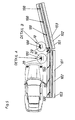
- FIG. 5 shows two roadway boundaries 101, which are formed as a stationary structure 102.
- the roadway boundaries 101 are formed as Botonleitance 103.
- These concrete guide walls 103 have a plurality of reflectors 100, wherein each one of these reflectors 100 can already be aligned with the mounting on the concrete Leit propositionn 103 to the road and the angle, the reflector surfaces 10 and 20, while it can be adjusted freely.
- the reflector 100 shown in detail A has parallel reflector surfaces 10 and 20
- the reflector 100 shown in detail B has reflector surfaces 10 and 20 which are at an angle of approximately 30 degrees to one another. This angle is freely selectable by suitable choice of the distances of the fasteners of the reflector 100 to the concrete guide wall 103.
- the reflector surfaces 10 and 20 can also follow a curved roadway, such as in a curve, even mounted on straight concrete guide walls 103.
Landscapes
- Engineering & Computer Science (AREA)
- Architecture (AREA)
- Civil Engineering (AREA)
- Structural Engineering (AREA)
- Road Signs Or Road Markings (AREA)
Applications Claiming Priority (1)
| Application Number | Priority Date | Filing Date | Title |
|---|---|---|---|
| AT0046210A AT509462B1 (de) | 2010-03-23 | 2010-03-23 | Reflektor für fahrbahnbegrenzungen |
Publications (2)
| Publication Number | Publication Date |
|---|---|
| EP2369059A2 true EP2369059A2 (fr) | 2011-09-28 |
| EP2369059A3 EP2369059A3 (fr) | 2013-09-25 |
Family
ID=44201048
Family Applications (1)
| Application Number | Title | Priority Date | Filing Date |
|---|---|---|---|
| EP11002281.1A Withdrawn EP2369059A3 (fr) | 2010-03-23 | 2011-03-21 | Réflecteur pour limitations de voie |
Country Status (2)
| Country | Link |
|---|---|
| EP (1) | EP2369059A3 (fr) |
| AT (1) | AT509462B1 (fr) |
Cited By (1)
| Publication number | Priority date | Publication date | Assignee | Title |
|---|---|---|---|---|
| WO2014164686A1 (fr) * | 2013-03-12 | 2014-10-09 | Dobbs Blaine Alan | Indicateur de chaussée solaire |
Citations (5)
| Publication number | Priority date | Publication date | Assignee | Title |
|---|---|---|---|---|
| JPS5854414U (ja) * | 1981-10-08 | 1983-04-13 | 渡辺 明一 | デリネ−タ |
| US4573763A (en) | 1984-12-18 | 1986-03-04 | Eagle Industries, Inc. | Three-dimensional flexible reflectors |
| EP0509788A1 (fr) | 1991-04-15 | 1992-10-21 | Allan Jarvis | Dispositif de signalisation routière et système de sécurité de la route |
| WO1999004095A1 (fr) | 1997-07-16 | 1999-01-28 | Minnesota Mining And Manufacturing Company | Revêtement reflechissant plisse pour glissiere de securite |
| DE10116354A1 (de) | 2001-04-02 | 2002-11-07 | Francesco Parrinello | Warnschild für Falschfahrer |
Family Cites Families (3)
| Publication number | Priority date | Publication date | Assignee | Title |
|---|---|---|---|---|
| DE3440468A1 (de) * | 1984-11-06 | 1986-08-21 | Ernst Ing.(grad.) 7060 Schorndorf Roethke | Optisches signal- bzw. informations-geraet |
| IE63963B1 (en) * | 1989-09-14 | 1995-06-28 | Paul Browne | A sign for mounting at a road bend |
| US6676331B1 (en) * | 2001-09-28 | 2004-01-13 | Alfredo Casale | Roadway delineator for new jersey-type concrete barriers |
-
2010
- 2010-03-23 AT AT0046210A patent/AT509462B1/de not_active IP Right Cessation
-
2011
- 2011-03-21 EP EP11002281.1A patent/EP2369059A3/fr not_active Withdrawn
Patent Citations (5)
| Publication number | Priority date | Publication date | Assignee | Title |
|---|---|---|---|---|
| JPS5854414U (ja) * | 1981-10-08 | 1983-04-13 | 渡辺 明一 | デリネ−タ |
| US4573763A (en) | 1984-12-18 | 1986-03-04 | Eagle Industries, Inc. | Three-dimensional flexible reflectors |
| EP0509788A1 (fr) | 1991-04-15 | 1992-10-21 | Allan Jarvis | Dispositif de signalisation routière et système de sécurité de la route |
| WO1999004095A1 (fr) | 1997-07-16 | 1999-01-28 | Minnesota Mining And Manufacturing Company | Revêtement reflechissant plisse pour glissiere de securite |
| DE10116354A1 (de) | 2001-04-02 | 2002-11-07 | Francesco Parrinello | Warnschild für Falschfahrer |
Cited By (4)
| Publication number | Priority date | Publication date | Assignee | Title |
|---|---|---|---|---|
| WO2014164686A1 (fr) * | 2013-03-12 | 2014-10-09 | Dobbs Blaine Alan | Indicateur de chaussée solaire |
| CN105229235A (zh) * | 2013-03-12 | 2016-01-06 | 布莱恩-艾伦·多布斯 | 太阳能道路轮廓标 |
| US9695996B2 (en) | 2013-03-12 | 2017-07-04 | Inq-Energy, Inc. | Solar-powered roadway delineator |
| CN105229235B (zh) * | 2013-03-12 | 2018-06-26 | 布莱恩-艾伦·多布斯 | 太阳能道路轮廓标 |
Also Published As
| Publication number | Publication date |
|---|---|
| AT509462B1 (de) | 2011-09-15 |
| EP2369059A3 (fr) | 2013-09-25 |
| AT509462A4 (de) | 2011-09-15 |
Similar Documents
| Publication | Publication Date | Title |
|---|---|---|
| DE102015222174B4 (de) | Radhausabdeckung für eine Kraftfahrzeugkarosserie und hiermit ausgestattetes Kraftfahrzeug | |
| EP2650196B1 (fr) | Toit de cabine pour poste de commande d'une machine de construction de chaussée | |
| DE102007061812A1 (de) | Kraftfahrzeug mit einer Luftleitvorrichtung | |
| EP3341538B1 (fr) | Store à bras articulé pour véhicules en forme d'éventail | |
| DE2546759A1 (de) | Aussenrueckblickspiegel fuer kraftfahrzeuge | |
| DE3413163C2 (de) | Absperrbake für Verkehrswege | |
| DE102020100493A1 (de) | Torpfosten für Sichtschutz | |
| AT509462B1 (de) | Reflektor für fahrbahnbegrenzungen | |
| EP1504967B1 (fr) | Support réglable pour un capteur | |
| EP3495227A1 (fr) | Passage entre deux parties de véhicule reliées de manière mobile | |
| EP1818198A1 (fr) | Dispositif d'acheminement de fluide, en particulier dispositif d'évacuation d'air pour véhicules | |
| DE202014003576U1 (de) | Rahmenlose Kennzeichenhalterung | |
| DE102011121401A1 (de) | Kraftfahrzeugkarosserie | |
| DE202010010684U1 (de) | Spannrahmen | |
| DE102004015721B4 (de) | Schutzeinrichtung für Gebäudeteile und -einbauteile | |
| EP1889742B1 (fr) | Véhicule automobile avec un réservoir | |
| EP2058786A1 (fr) | Dispositif d'affichage lumineux pour la représentation de signaux dans des tunnels ou autres | |
| DE10247418B4 (de) | Vorderer Stoßfänger eines LKW mit einer unten liegenden Bugschürze | |
| DE102013014240B4 (de) | Windabweiser für eine Windschutzscheibe und zusätzliche Windschutzscheibe | |
| DE202015101299U1 (de) | Schrankengelenkvorrichtung | |
| DE69420114T2 (de) | Befestigungsmittel für Blendschutzzaun auf Leitplanken | |
| CH688483A5 (de) | Verkehrssperre. | |
| DE102021003734B3 (de) | Motorradaerodynamikschutzvorichtung | |
| DE202005008391U1 (de) | Übergang bei Verkehrswegen von einer Betongleitwand auf eine Schutzplankenanordnung | |
| EP1516755B1 (fr) | Dispositif d'attelage articulé |
Legal Events
| Date | Code | Title | Description |
|---|---|---|---|
| PUAI | Public reference made under article 153(3) epc to a published international application that has entered the european phase |
Free format text: ORIGINAL CODE: 0009012 |
|
| AK | Designated contracting states |
Kind code of ref document: A2 Designated state(s): AL AT BE BG CH CY CZ DE DK EE ES FI FR GB GR HR HU IE IS IT LI LT LU LV MC MK MT NL NO PL PT RO RS SE SI SK SM TR |
|
| AX | Request for extension of the european patent |
Extension state: BA ME |
|
| PUAL | Search report despatched |
Free format text: ORIGINAL CODE: 0009013 |
|
| AK | Designated contracting states |
Kind code of ref document: A3 Designated state(s): AL AT BE BG CH CY CZ DE DK EE ES FI FR GB GR HR HU IE IS IT LI LT LU LV MC MK MT NL NO PL PT RO RS SE SI SK SM TR |
|
| AX | Request for extension of the european patent |
Extension state: BA ME |
|
| RIC1 | Information provided on ipc code assigned before grant |
Ipc: E01F 9/015 20060101AFI20130819BHEP Ipc: E01F 9/00 20060101ALI20130819BHEP Ipc: E01F 9/03 20060101ALI20130819BHEP |
|
| 17P | Request for examination filed |
Effective date: 20140324 |
|
| RBV | Designated contracting states (corrected) |
Designated state(s): AL AT BE BG CH CY CZ DE DK EE ES FI FR GB GR HR HU IE IS IT LI LT LU LV MC MK MT NL NO PL PT RO RS SE SI SK SM TR |
|
| 17Q | First examination report despatched |
Effective date: 20160415 |
|
| STAA | Information on the status of an ep patent application or granted ep patent |
Free format text: STATUS: THE APPLICATION IS DEEMED TO BE WITHDRAWN |
|
| 18D | Application deemed to be withdrawn |
Effective date: 20160826 |