EP2369193A1 - Structure de montage d'actionneur d'embrayage pour moteur à combustion interne - Google Patents
Structure de montage d'actionneur d'embrayage pour moteur à combustion interne Download PDFInfo
- Publication number
- EP2369193A1 EP2369193A1 EP11153625A EP11153625A EP2369193A1 EP 2369193 A1 EP2369193 A1 EP 2369193A1 EP 11153625 A EP11153625 A EP 11153625A EP 11153625 A EP11153625 A EP 11153625A EP 2369193 A1 EP2369193 A1 EP 2369193A1
- Authority
- EP
- European Patent Office
- Prior art keywords
- clutch actuator
- clutch
- containing part
- oil
- internal combustion
- Prior art date
- Legal status (The legal status is an assumption and is not a legal conclusion. Google has not performed a legal analysis and makes no representation as to the accuracy of the status listed.)
- Granted
Links
Images





Classifications
-
- F—MECHANICAL ENGINEERING; LIGHTING; HEATING; WEAPONS; BLASTING
- F16—ENGINEERING ELEMENTS AND UNITS; GENERAL MEASURES FOR PRODUCING AND MAINTAINING EFFECTIVE FUNCTIONING OF MACHINES OR INSTALLATIONS; THERMAL INSULATION IN GENERAL
- F16D—COUPLINGS FOR TRANSMITTING ROTATION; CLUTCHES; BRAKES
- F16D13/00—Friction clutches
- F16D13/58—Details
-
- F—MECHANICAL ENGINEERING; LIGHTING; HEATING; WEAPONS; BLASTING
- F16—ENGINEERING ELEMENTS AND UNITS; GENERAL MEASURES FOR PRODUCING AND MAINTAINING EFFECTIVE FUNCTIONING OF MACHINES OR INSTALLATIONS; THERMAL INSULATION IN GENERAL
- F16D—COUPLINGS FOR TRANSMITTING ROTATION; CLUTCHES; BRAKES
- F16D2300/00—Special features for couplings or clutches
- F16D2300/12—Mounting or assembling
Definitions
- the present invention relates to a structure of mounting a clutch actuator for engaging and disengaging a shift clutch of an internal combustion engine.
- Patent Document 1 An internal combustion engine with such a clutch actuator mounted to an engine case is disclosed in Patent Document 1.
- Patent Document 1 which is equipped with a twin clutch type transmission, a twin clutch operated by oil pressure is provided at an end portion of a main shaft of the transmission, and a clutch cover mounted to a right side surface of a crankcase is projected to the right side to cover the twin clutch.
- the crankcase is provided at its inner surface with a clutch actuator containing part bulged to the inner side.
- a clutch actuator for engaging and disengaging the twin clutch is inserted into the clutch actuator containing part through an opening formed in that surface of the clutch actuator containing part which is the same as the mating surface, and the clutch actuator is detachably mounted.
- a control oil passage for supplying a working oil to the shift clutch is formed in communication with the inside of a side wall of the crankcase and the inside of a side wall of the clutch cover.
- the structure for mounting the clutch actuator disclosed in Patent Document 1 is disposed on the inner side of the crankcase and the clutch cover. Therefore, for performing clutch actuator maintenance or the like, the clutch cover which is formed with the control oil passage and large in size must be dismounted, and workability is poor accordingly.
- the present invention has been made in consideration of this point. Accordingly, it is an object of the present invention to provide a clutch actuator mounting structure for internal combustion engine which has excellent maintainability such that clutch actuator maintenance and the like can be carried out without dismounting an engine case.
- a clutch actuator mounting structure for an internal combustion engine (E) including, in an engine case (70, 31R), a power transmission mechanism designed to transmit rotational power of a crankshaft (30) to an output shaft (37) through a shift clutch (41) and a transmission (T), characterized in that the engine case is formed with a clutch actuator containing part (72) in which a clutch actuator (81A, 81B) for engaging/disengaging the shift clutch (41) is contained; and the clutch actuator containing part (72) has a clutch actuator mounting/dismounting port (72h) through which to mount and dismount the clutch actuator (81A, 81B), the clutch actuator mounting/dismounting port (72h) being formed to be exposed to the exterior.
- the invention as described in claim 2 is characterized in that, in the clutch actuator mounting structure for the internal combustion engine as described in claim 1, the engine case (70) formed with the clutch actuator containing part (72) is a case cover for covering the shift clutch on a lateral side of a crankcase (31L, 31R) for rotatably supporting the crankshaft (30) thereon, and the clutch actuator containing part (72) is formed to project to a lateral side of the case cover (70).
- the invention as described in claim 3 is characterized in that, in the clutch actuator mounting structure for the internal combustion engine as described in claim 2, the internal combustion engine (E) is mounted on a vehicle with the crankshaft (30) oriented in a left-right direction; the shift clutch (41) is provided at that shaft end of a main shaft (35) in the transmission (T) provided inside the crankcase (31L, 31R) which is projected into the inside of the case cover (70); the case cover (70) has a bulged containing part (71) in which a gear pair (43, 44) for transmitting power from the crankshaft (30) to the shift clutch (41) and the shift clutch (41) are contained, the bulged containing part (71) being bulged to a lateral side; and the case cover (70) has the clutch actuator containing part (72) projected into a space on the lower side of the bulged containing part (71).
- the invention as described in claim 4 is characterized in that, the clutch actuator mounting structure for the internal combustion engine as described in claim 3, the case cover (70) is provided with an oil filter (85) so as to overlap, in front view, with the front side of the clutch actuator containing part (72) in the space on the lower side of the bulged containing part (71) of the case cover (70).
- the oil filter (85) has an oil filter housing (73) in which to contain a filter element (86), the oil filter housing (73) being projectingly formed as part of the case cover (70).
- the invention as described in claim 6 is characterized in that, in the clutch actuator mounting structure for the internal combustion engine as described in claim 5, the clutch actuator containing part (72) is formed on the inner side relative to an outside part of the oil filter housing (73) in a vehicle body width direction.
- the invention as described in claim 7 is characterized in that, in the clutch actuator mounting structure for the internal combustion engine as described in claim 5 or claim 6, the clutch actuator containing part (72) is formed to have its longitudinal direction oriented in a front-rear direction, and the oil filter housing (73) is formed in such a shape that the filter element (86) being cylindrical in shape is contained in the oil filter housing (73) with the center axis of the cylinder oriented in the front-rear direction.
- the invention as described in claim 8 is characterized in that, in the cutch actuator mounting structure for the internal combustion engine as described in claim 7, the clutch actuator containing part (72) is formed with the clutch actuator mounting/dismounting port (72h) oriented rearward; and the oil filter housing (73) is formed with a filter element mounting/dismounting port (73h) through which to mount and dismount the filter element (86), the filter element mounting/dismounting port (73h) being oriented forward.
- the invention as described in claim 9 is characterized in that, in the clutch actuator mounting structure for the internal combustion engine as described in claim 7 or claim 8, the clutch actuator containing part (72) is formed at a vertical position such that its lower end is proximate to or in contact with a lower end edge of the case cover (70), and the oil filter housing (73) has its upper end located at substantially the same vertical position as an upper end of the clutch actuator containing part (72).
- the shift clutch is a twin clutch (41); the two clutch actuators (81A, 81B) for respectively driving clutches of the twin clutch (41) by oil pressure are provided on a front lower side of the twin clutch (41); and a pair of control oil passages (76A, 76B) for supplying a working oil from the clutch actuators (81A, 81B) to the corresponding shift clutches (41A, 41b) respectively are formed at an outside surface of the right case cover (70) in the state of being oriented obliquely and extending rectilinearly in parallel to each other.
- a first control oil pressure sensor (79A) is upwardly projectingly provided at a substantially central position of a first control oil passage (76A) which is an upper-side one of the pair of control oil passages (76A, 76B) oriented obliquely; and a second control oil pressure sensor (79B) is rearwardly projectingly provided in a second control oil passage (76B) which is a lower-side one of the pair of control oil passages (76A, 76B), at a height position between the shift clutch (41) and the clutch actuators (81A, 81B).
- the invention as described in claim 12 is characterized in that, in the clutch actuator mounting structure for the internal combustion engine as described in any one of claims 4 to 11, a discharged oil from an oil pump (50) is led into the oil filter (85); and a discharge oil pressure sensor (88) for detecting the oil pressure of the discharged oil is forwardly projectingly provided on the oil filter (85).
- the invention as described in claim 13 is characterized in that, in the clutch actuator mounting structure for the internal combustion engine as described in claim 12, the discharge oil pressure sensor (88) is mounted to a filter cover member (87) for closing the filter element mounting/dismounting port (73h), which is oriented forward, of the oil filter housing (73) of the oil filter (85).
- the clutch actuator containing part (72) formed as part of the engine case (70, 31R) has the clutch actuator mounting/dismounting port (72h) formed to be exposed to the exterior. This ensures that the clutch actuator (81A, 81B) contained in the clutch actuator containing part (72) can be put in and out through the clutch actuator mounting/dismounting port (72h) without dismounting the engine case (70, 31R), and maintainability is extremely good accordingly.
- the case cover (70) for covering the shift clutch (41) has the clutch actuator containing part (72) formed to project to a lateral side, and the clutch actuator mounting/dismounting port (72h) formed as part of the clutch actuator containing part (72) is exposed to the exterior. Therefore, the clutch actuator (81A, 81B) can be put in and out through the clutch actuator mounting/dismounting port (72h) of the case cover (70) without dismounting the case cover (70), and maintainability is extremely good accordingly.
- the cutch actuator containing part (72) formed to project to a lateral side of the case cover (70) is formed with the clutch actuator mounting/dismounting port (72h) exposed to the exterior, so that the clutch actuator mounting structure can be simplified.
- the clutch actuator containing part (72) is projectingly formed by utilizing the space on the lower side of that bulged containing part (71) of the case cover (70) in which the gear pair (43, 44) for transmitting power from the crankshaft (30) to the shift clutch (41) at an end portion of the main shaft (35) and the shift clutch (41) are contained and which is formed to be bulged to a lateral side.
- This ensures that the clutch actuator containing part (72) can be formed without enlarging the internal combustion engine in overall left-right width or overall front-rear width, and it is therefore possible to obviate an enlargement of the size of the internal combustion engine.
- the case cover (70) is provided with the oil filter (85) so as to overlap, in front view, with the front side of the clutch actuator containing part (72) in the space on the lower side of the bulged containing part (71) of the case cover (70).
- the oil filter (85) has the oil filter housing (73) in which to contain the filter element (86), the oil filter housing (73) being projectingly formed as part of the case cover (70).
- the oil filter housing (73) is not formed separately from the case cover (70) but formed integrally with the case cover (70), which leads to a reduction in the number of component parts and to enhanced maintainability.
- the clutch actuator containing part (72) is formed on the inner side relative to the outside part of the oil filter housing (73) in the vehicle body width direction. Therefore, the oil filter housing (73) serves as a shield by which the clutch actuator (81A, 81B) can be protected from flying stones and the like.
- the clutch actuator containing part (72) is formed to have its longitudinal direction oriented in the front-rear direction, and the oil filter housing (73) is formed in such a shape that the filter element (86) being cylindrical in shape is contained in the oil filter housing (73) with the center axis of the cylinder oriented in the front-rear direction.
- This ensures that both the oil filter housing (73) and the clutch actuator containing part (72) formed in the space on the lower side of the bulged containing part (71) of the case cover (70) can be made small in vertical width and left-right width, so that the internal combustion engine as a whole is not enlarged in vertical width or left-right width.
- the clutch actuator containing part (72) and the oil filter housing (73) set proximate to each other, it is possible to obviate an enlargement of the size of the internal combustion engine.
- the clutch actuator containing part (72) is formed with the clutch actuator mounting/dismounting port (72h) oriented rearward, and the oil filter housing (73) is formed with a filter element mounting/dismounting port (73h) through which to mount and dismount the filter element (86), the filter element mounting/dismounting port (73h) being oriented forward.
- This makes it possible to mount and dismount the clutch actuators (81A, 81B) and the filter element (86) without interference between the clutch actuator containing part (72) and the oil filter housing (73) which are laid out proximate to each other. Consequently, easy maintenance can be achieved.
- the clutch actuator containing part (72) is formed at a vertical position such that its lower end is proximate to or in contact with the lower end edge of the case cover (70). This ensures that a lowering of the center of gravity can be contrived by lowering the clutch actuator containing part (72) as much as possible.
- the oil filter housing (73) has its upper end located at substantially the same vertical position as the upper end of the clutch actuator containing part (72). This enables effective utilization of the space on the upper side of the clutch actuator containing part (72) and the oil filter housing (73) which have their upper ends at substantially the same vertical position.
- the two clutch actuators (81A, 81B) for respectively driving clutches of the twin clutch (41) by oil pressure are provided on the front lower side of the twin clutch (41), and the pair of control oil passages (76A, 76B) for supplying the working oil from the clutch actuators (81A, 81B) to the corresponding shift clutches (41A, 41B) respectively are formed at the outside surface of the right case cover (70) in the state of being oriented obliquely and extending rectilinearly in parallel to each other.
- a space (S) which is opened on the rear side and the lower side and the outer side and which is suitable for putting the driver's foot can be secured near the case cover (70).
- the first control oil pressure sensor (79A) is upwardly projectingly provided at the substantially central position of the first control oil passage (76A) which is the upper-side one of the pair of control oil passages (76A, 76B) oriented obliquely
- the second control oil pressure sensor (79B) is rearwardly projectingly provided at the second control oil passage (76B) which is the lower-side one of the pair of control oil passages (76A, 76B), at a height position between the shift clutch (41) and the clutch actuators (81A, 81B).
- the oil discharged from the oil pump (50) is led into the oil filter (85), and the discharge oil pressure sensor for detecting the oil pressure of the discharged oil is forwardly projectingly provided on the oil filter (85).
- the discharge oil pressure sensor (88) can be provided while utilizing the space on the front side of the oil filter (85) and while obviating, as securely as possible, the projection of the discharge oil pressure sensor (88) from the internal combustion engine.
- the discharge oil pressure sensor (88) is mounted to the filter cover member (87) for closing the filter element mounting/dismounting port (73h), which is oriented forward, of the oil filter housing (73) of the oil filter (85). Therefore, by preliminarily mounting the discharge oil pressure sensor to the filter cover member (87) and handling them as one body, it is possible to enhance workability.
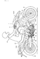
- FIG. 1 is a right side view of a motorcycle 130 on which an internal combustion engine according to this embodiment is mounted.
- a body frame 2 of the motorcycle 1 includes a head pipe 3, main frames 4 extending obliquely rearward from the head pipe 3, a center frame 5 extending downward from the rear ends of the main frames 4, a down frame 6 extending downward from the head pipe 3, seat stays 7 extending rearward from an upper portion of the center frame 5, and a mid frame 8 bridgingly interposed between a rear portion of the center frame 5 and rear portions of the seat stays 7.
- a front fork 10 supporting a front wheel 9 thereon is steerably supported on the head pipe 3, and a steering handle 11 is connected to an upper portion of the front fork 10.
- a rear fork 13 supporting a rear wheel 12 thereon is vertically swingably supported through a pivot bolt 25 of the center frame 5.
- An internal combustion engine E is a 2-cylinder 4-stroke internal combustion engine, and is supported by the main frame 4, the center frame 5 and the down frame 6. Rotational power of an output shaft of the internal combustion engine E is transmitted to the rear wheel 12 through a rear wheel driving chain 15.
- a fuel tank 16 is mounted between the left and right main frames 4, and a tandem type seat 17 on which a driver P and a pillion passenger can be seated is mounted on the left and right seat stays 7 on the rear side of the fuel tank 16.
- a step holder 20 is provided at a joint between a lower portion of the center frame 5 and the mid frame 8, and a foot step 21 is projectingly provided on the step holder 20.
- a foot step 21 is provided at a position in left-right symmetry with the position of the above-mentioned foot step 21.
- the internal combustion engine E is mounted in a horizontal posture on the body frame 2, with its crankshaft 30 oriented in the left-right direction, which is the vehicle body width direction.
- the crankshaft 30 is rotatably supported between an upper crankcase 31U and a lower crankcase 31L into which a crankcase is bisected, with bearings therebetween.
- a cylinder block 32, a cylinder head 33 and a cylinder head cover 34 which are sequentially stacked and slanted to the front side are provided in such a manner as to project along a forwardly upward direction from the upper crankcase 31U.
- the lower side of the lower crankcase 31L is closed with an oil pan 39.
- a main shaft 35 of a transmission T is rotatably borne on the upper crankcase 31U at a slightly obliquely upper position on the rear side of the crankshaft 30 and in parallel to the crankshaft 30, through bearings 36, 36 therebetween.
- a counter shaft 37 as an output shaft is rotatably borne between the upper crankcase 31U and the lower crankcase 31L, through bearings 38, 38 therebetween (see FIGS. 2 and 3 ).
- the main shaft 35 of the transmission T has a structure wherein a main outer shaft 35o is fitted over a main inner shaft 35i so as to be capable of relative rotation, and the main shafts are provided respectively with pluralities of drive gears m.
- a plurality of driven gears c provided on the counter shaft 37 and the corresponding drive gears m are normally meshed with each other.
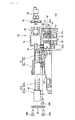
- the main outer shaft 35o and the main inner shaft 35i rightwardly penetrating the bearing 36 fitted to a right side wall of the upper crankcase 31U are provided thereon with a twin clutch 41 composed of a pair of a first friction clutch 41A and a second friction clutch 41B.
- a primary driven gear 43 is fitted to clutch outers of both the clutches. Engagement/disengagement of the first friction clutch 41A and the second friction clutch 41B is controlled respectively by oil pressures supplied through in-shaft oil passages 49a and 49b formed on the outer side and the inner side in the inside of the main shaft 35, whereby shifting of the transmission T is conducted.
- a right case cover 70 is put on a right side surface of a crankcase obtained by uniting the upper crankcase 31U and the lower crankcase 31L.
- the friction clutches 41A and 41B provided on the right side relative to the right side walls of the upper and lower crankcases 31U and 31L, the primary driven gear 43, a primary drive gear 44 fitted to the crankshaft 30 and meshed with the primary driven gear 43, etc. are covered by the right case cover 70.
- a control oil pump 50 provided at a front portion of the right side wall of the lower crankcase 31L is also covered by the right case cover 70 (see FIG. 2 ).
- a control oil pump case 51 is formed with a circular recess 51d opened on the left side for containing therein an inner rotor 53 and an outer rotor 54 which are provided respectively on the inner and outer sides and are meshed with each other.
- the circular recess 51d is covered with a partition plate 57 brought into contact with the oil pump case 51 from the left side.
- a lubricating oil pump 60 is provided on the left side of the partition plate 57, with a pump drive shaft 52 disposed in common for the lubricating oil pump 60 and the control oil pump 50.
- the lubricating oil pump 60 is formed with a circular recess 61d opened on the right side for containing therein an inner rotor 63 and an outer rotor 64 which are provided respectively on the inner and outer sides and are meshed with each other.
- the circular recess 61d is covered with the partition plate 57 brought into contact with the lubricating oil pump case 61 from the right side.
- the partition plate 57 is interposed between the control oil pump case 51 and the lubricating oil pump case 61, thereby partitioning the control oil pump 50 and the lubricating oil pump 60 from each other.
- the pump drive shaft 52 provided in common for both the oil pumps 50 and 60 is rotatably borne, with both its ends borne on the control oil pump case 51 and the lubricating oil pump case 61 and with its center borne on the partition plate 57, while being oriented in the left-right direction.
- the circular recess 51d is formed in a mating surface of the control oil pump case 51 for mating with the partition plate 57, whereas a suction oil passage 55 dug to be deeper than the circular recess 51d is formed along a little less than half a circumference around the front side of a bearing circular hole 51b of the pump drive shaft 52 and is formed to further extend downward and expand largely to the front and rear sides.
- a discharge oil passage 56 dug to be deeper than the circular recess 51d is formed along a little less than half a circumference around the rear side of the bearing circular hole 51b and is formed to further extent in a rearwardly downward direction toward the filter case 61.
- the partition plate 57 brought into contact with the mating surface of the control oil pump case 51 has a circular suction port 57h bored correspondingly to that portion of the suction oil passage 55 which is expanded rearward. Though not shown, a suction pipe extending from an oil strainer disposed along a bottom surface of the oil pan 39 is connected to the suction port 57h.
- the control oil pump case 51 is formed with a discharge port 51h opened in its portion on the rear side of the discharge oil passage 56 (see FIG. 16 ).
- a relief valve device 58 as an oil return mechanism is fitted in the state of being oriented in a direction orthogonal to the pump drive shaft 52.
- a valve element 59 of the relief valve device 58 fronts on the discharge oil passage 56.
- the discharge oil pressure exceeds a predetermined pressure
- a movement of the valve element 59 results in opening of the valve, whereby the discharge oil passage 56 and the suction oil passage 55 are made to communicate with each other, and a portion of the oil discharged into the discharge oil passage 56 is returned into the suction oil passage 55. Consequently, an adjustment is made so that the discharge oil pressure would not reach or exceeds a predetermined oil pressure.
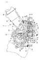
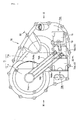
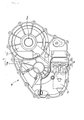
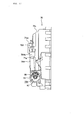
- FIG. 7 A right side view of the right case cover 70 is shown in FIG. 7 , a left side view of the same in FIG. 8 , a rear view of the same in FIG. 9 , a front view of the same in FIG. 10 , and a sectional view (sectional view taken along line XI-XI of FIG. 7 ) of the same is shown in FIG. 11 .
- the right case cover 70 has a structure in which a roughly upper half portion of its side wall facing the right crankcase 31R is bulged rightward to form a bulged containing part 71, a rear half portion of the bulged containing part 71 is further bulged to form a clutch containing part 71c for containing the twin clutch 41, and a front half portion of the bulged containing part 71 forms a gear containing part 71g for containing a pair of the primary drive gear 44 and the primary driven gear 43 which are meshed with each other and transmit power from the crankshaft 30 to the twin clutch 41.
- the right case cover 70 projects from a side wall into a space on the lower side of the bulged containing part 71 to form a clutch actuator containing part 72 for containing therein an upper-lower pair of a first clutch actuator 81A and a second clutch actuator 81B.
- the clutch actuator containing part 72 has a rectangular tubular shape oriented in the front-rear direction, in which a valve case 72v is formed in a front half, and a solenoid case 72s is formed in a rear half.
- the valve case 72v has a structure in which respective valve element driving parts 81Av and 81Bv of the first and second clutch actuators 81A and 81B are respectively inserted into circular holes which are bored on upper and lower sides while oriented in the front-rear direction and are closed at their front ends.
- the solenoid case 72s is provided at its rear end with a clutch actuator mounting/dismounting port 72h oriented rearward, opened in a vertically long rectangular shape and exposed to the exterior (see FIG. 9 ); respective linear solenoids 81As and 81Bs of the first and second clutch actuators 81A and 81B are inserted, while aligned on the upper and lower sides, in an internal common space.
- the first and second clutch actuators 81A and 81B are inserted as one body via the clutch actuator mounting/dismounting port 72h into the clutch actuator containing part 72, in the condition where those base parts of the valve element drive parts 81Av and 81Bv which are connected to the solenoids 81As and 81Bs are supported by a support plate 82.
- the support plate 82 is anchored by a bolt 82b (see FIG. 4 ).
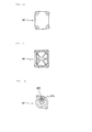
- the clutch actuator mounting/dismounting port 72h is closed with a rectangular plate-shaped clutch actuator cover member 83 (see FIGS. 12 and 13 ), and four corners of the clutch actuator cover member 83 are screwed by bolts 83b.
- the right case cover 70 has a structure in which an oil filter housing 73 of an oil filter 85 is formed to project from a side wall, on the front side of the clutch actuator containing part 72 in the space on the lower side of the bulged containing part 71. Therefore, the oil filter 85 can be provided without enlarging the internal combustion engine E in overall left-right width or overall front-rear width, and it is possible to avoid an enlargement of the size of the internal combustion engine E.
- the oil filter housing 73 is not formed separately from the right case cover 70 but formed integrally with the right case cover 70, which leads to a reduction in the number of component parts and to favorable maintainability.
- the oil filter housing 73 has a cylindrical shape with a center axis oriented in the front-rear direction, its rear end proximate to the valve case 72v of the clutch actuator containing part 72 is closed, it is formed at its front end with a filter element mounting/dismounting port 73h being opened toward the front side in a circular shape and exposed to the exterior (see FIG. 10 ), and a filter element 86 is inserted therein from the front side (see FIG. 5 ).
- the oil filter housing 73 cylindrical in shape is formed at such a position as to overlap with the clutch actuator containing part 72 in front view shown in FIG. 10 , and is restrained from projecting sideways.
- the oil filter housing 73 is cylindrical in shape and therefore its corners do not project sideways, the bank angle of the vehicle body can be designed to be large.
- the oil filter housing 73 is projected toward the right side relative to the clutch actuator containing part 72, and the clutch actuator containing part 72 is formed on the inner side relative to an outside portion of the oil filter housing 73 in the vehicle body width direction (see FIGS. 9 and 10 ). Therefore, the oil filter housing 73 serves as a shield, by which the clutch actuators 81A and 81B can be protected against flying stones and the like coming from the front side.
- the filter element mounting/dismounting port 73h oriented forward is closed with a circular plate-shaped filter cover member 87 (see FIGS. 14 and 15 ) put from the front side.
- the filter cover member 87 is anchored by two bolts 87b screwed at upper and lower positions.
- the oil filter housing 73 is located at such a position as to cover a lower portion of the control oil pump case 51 from the right side.
- a circular hole communicating with the inside of the oil filter housing 73 is formed to face the discharge port 51h of the control oil pump case 51, both of them are interconnected by a connection pipe 74 (see FIG. 4 ), and the oil discharged from the control oil pump 50 is led through the discharge oil passage 56 and the connection pipe 74 to the upstream side of the filter in the oil filter housing 73.
- connection oil pipe 75 is formed between the center of a rear wall of the oil filter housing 73 and the valve case 72v constituting a front half of the clutch actuator containing part 72.
- the connection oil pipe 75 communicates with the downstream side of the filter in the center of the filter element 86. Therefore, the oil filtered by the filter element 86 of the oil filter 85 is supplied through the connection oil pipe 75 into the valve case 72v.
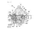
- the filter cover member 87 is provided with a mount boss part 87s for mounting a discharge oil pressure sensor 88, the mount boss part 87s being projectingly formed at an eccentric position.
- the mount boss part 87s is provided with a circular hole 87h in which to insert a pressure sensing part of the discharge oil pressure sensor 88, the circular hole 87h being bored from the face side to the back side.
- the tip of the circular hole 87h is tapered, and is then opened to the back side via a small hole. Therefore, the oil discharged from the control oil pump 50 is led through the connection pipe 74 to the upstream side of the filter in the oil filter housing 73.
- the discharged oil enters into the circular hole 87h in the filter cover member 87, to reach the pressure sensing part of the discharge oil pressure sensor 88, so that the discharge oil pressure sensor 88 detects the pressure of the oil discharged from the control oil pump 50.
- the oil supplied from the oil filter 85 into the valve case 72v of the clutch actuator containing part 72 is distributed to the respective valve element driving parts 81Av and 81Bv of the first and second clutch actuators 81A and 81B. Then, the working oils controlled by the valve element driving parts 81Av and 81Bv driven by the linear solenoids 81As and 81Bs respectively are served to drive control of the first and second friction clutches 41A and 41B of the twin clutch 41.
- the right case cover 70 is provided with a pair of mutually parallel, first and second control oil passages 76A and 76B which offer rectilinear connection between the valve case 72v of the clutch actuator containing part 72 and a central portion of the clutch containing part 71c containing the twin clutch 41 therein; the first and second control oil passages 76A and 76B are formed to expand in tubular shape on the surface of the right case cover 70.
- the valve case 72v of the clutch actuator containing part 72 is located on a front lower side of the clutch containing part 71c located at an upper portion of the rear half of the right case cover 70. Accordingly, the first and second control oil passages 76A and 76B extend rearwardly upward from the valve case 72v.
- the center of the clutch containing part 71c supports a portion near the right end of the crankshaft 35 through a bearing 77, together with the clutch inner of the first friction clutch 41A.
- a bottomed cylinder part 71cc covering the right end of the crankshaft 35 is formed to bulge to the right side.
- the first and second control oil passages 76A and 76B are connected to the bottomed cylinder part 71cc, and communicate with the inside of the latter.
- a partition member 78 is interposed between an inner peripheral surface of the bottomed cylinder part 71cc and an outer peripheral surface of the right end of the crankshaft 35.
- the partition member 78 is provided, at both ends of its cylindrical portion fitted to the right end of the crankshaft 35, with flange parts having an outside diameter equal to the inside diameter of the bottomed cylinder part 71cc.
- the inside of an outer peripheral groove between both the flange parts is divided into two spaces.
- the outer peripheral groove on one side which communicates with the first control oil passage 76A as the upper-side one of the pair of first and second control oil passages 76A and 76B oriented slantly, penetrates the cylindrical portion of the partition member 78 and the right end of the crankshaft 35, to communicate with the in-shaft oil passage 49a.
- the outer peripheral groove on the other side which communicates with the second control oil passage 76B on the lower side, penetrates the outer-side (right-side) flange part of the partition member 78, and extends around along a bottom surface of the bottomed cylinder part 71cc, to communicate with the in-shaft oil passage 49b.
- the working oil controlled by driving of the first clutch actuator 81A is supplied through the first control oil passage 76A and the in-shaft oil passage 49a to the first friction clutch 41A, to effect engagement/disengagement of the first friction clutch 41A.
- the working oil controlled by driving of the second clutch actuator 81B is supplied through the second control oil passage 76B and the in-shaft oil passage 49B, to effect engagement/disengagement of the second friction clutch 41B.
- an upper half portion of the right case cover 70 is bulged to the right side to form the bulged containing part 71, and the clutch actuator containing part 72 is projectingly formed on the front lower side of the clutch containing part 71c further bulged from a rear half portion of the bulged containing part 71. Therefore, on the lower side of the clutch containing part 71c and on the rear side of the clutch actuator containing part 72, a recessed space S is formed which is opened on the three sides, namely, the rear side, the lower side and the right side.
- the first and second control oil passages 76A and 76B are formed in the state of being oriented slantly while interconnecting the bottomed cylinder part 71cc at the center of the clutch containing part 71c with the valve case 72v as the front portion of the clutch actuator containing part 72, and, therefore, they do not interfere with the recessed space S. Accordingly, the recessed space S is largely opened on the right side.
- the slantly oriented first control oil passage 76A on the upper side, of the right case cover 70 is provided at a substantially central position thereof with a sensor mounting boss part 76Ab having a mounting port directed upward.
- the second control oil passage 76B on the lower side is provided with a sensor mounting boss part 76Bb having a mounting port directed rearward, between the clutch containing part 71c and the clutch actuator containing part 72.
- a first control oil pressure sensor 79A is mounted to the sensor mounting boss part 76Ab of the first control oil passage 76A on the upper side, in the state of being oriented in the vertical direction and projecting upward; on the other hand, a second control oil pressure sensor 79B is mounted to the sensor mounting boss part 76Bb of the second control oil passage 76B on the lower side, in the state of being oriented in the front-rear direction and projecting rearward (see FIG. 5 ).
- the first control oil pressure sensor 79A detects the oil pressure in the first control oil passage 76A for effecting engagement/disengagement of the first friction clutch 41A
- the second control oil pressure sensor 79B detects the oil pressure in the second control oil passage 76B for effecting engagement/disengagement of the second friction clutch 41B.
- the oil pressures thus detected are served for enhancing the shift control properties of the twin clutch 41.
- the first control oil pressure sensor 79A mounted to the first control oil passage 76A in the state of being oriented in the vertical direction and the second control oil pressure sensor 79B mounted to the second control oil passage 76B in the state of being oriented in the front-rear direction are both located at a peripheral edge portion of the bulged clutch containing part 71c of the right case cover 70, and can be provided in a compact form at such positions that they do not interfere with the twin clutch 41 and that their projection to a lateral side is minimized.
- the first control oil pressure sensor 79A (indicated by two-dotted chain line in FIG. 10 ) is disposed compactly on the inner side (the left side of the vehicle body) relative to the bottomed cylinder part 71cc bulged at the center of the clutch containing part 71c of the right case cover 70.
- the second control oil pressure sensor 79B (indicated by two-dotted chain line in FIG. 9 ) is disposed compactly on the inner side relative to the bottomed cylinder part 71cc at the center of the clutch containing part 71c.
- the right case cover 70 in this internal combustion engine E is integrally provided with the clutch actuator containing part 72 in which to contain the first and second clutch actuators 81A and 81B for effecting engagement/disengagement of the twin clutch 41, the clutch actuator containing part 72 being projected sideways.
- the clutch actuator mounting/dismounting port 72h of the clutch actuator containing part 72 is formed to be exposed to the exterior. Therefore, the first and second clutch actuators 81A and 81B contained in the clutch actuator containing part 72 can be put in and out through the clutch actuator mounting/dismounting port 72h, without need to dismount the right case cover 70. Consequently, maintainability is extremely good.
- the clutch actuator containing part 72 formed to project to a lateral side of the right case cover 70 has the clutch actuator mounting/dismounting port 72h formed to be exposed to the exterior; therefore, the clutch actuator mounting structure is simplified.
- the right case cover 70 is provided with the bulged containing part 71 which has an upper half portion composed generally of the clutch containing part 71c and a gear containing part 71g and which is bulged sideways.
- the clutch actuator containing part 72 is projectingly formed by utilizing the space on the lower side of the bulged containing part 71. Therefore, as shown in FIG. 9 , the clutch actuator containing part 72 is restrained from projecting sideways, and is compactly disposed on the inner side (the left side of the vehicle body) relative to the bottomed cylinder part 71cc bulged at the center of the clutch containing part 71c of the right case cover 70.
- the clutch actuator containing part 72 is contained within the front-rear width of the bulged containing part 71 on the upper side. Accordingly, the clutch actuator containing part 72 can be formed without enlarging the internal combustion engine E in overall left-right width or overall front-rear width, so that it is possible to obviate an enlargement of the size of the internal combustion engine E.
- the oil filter housing 73 is formed on the front side of the clutch actuator containing part 72, in such a shape that the cylinder center axis of the cylindrical filter element 86 is oriented in the front-rear direction and that the filter element mounting/dismounting port 73h is directed forward.
- the clutch actuator containing part 72 is formed with the clutch actuator mounting/dismounting port 72h directed rearward. Therefore, notwithstanding the clutch actuator containing part 72 and the oil filter housing 73 are disposed proximate to each other, the first and second clutch actuators 81A and 81B and the filter element 86 can be mounted and dismounted without interference with each other (see FIG. 5 ).
- the first and second clutch actuators 81A and 81B and the oil filter 85 juxtaposed in the front-rear direction can be kept small in the front-rear width, and an enlargement of the size of the internal combustion engine E can be avoided.
- the clutch actuator containing part 72 is formed at such a vertical position that its lower end is proximate to or in contact with the lower end edge of the right case cover 70. Therefore, the clutch actuator containing part 72 can be disposed as low as possible, whereby lowering of the center of gravity can be contrived.
- the oil filter 85 is so formed that its upper end is located at substantially the same vertical position as the upper end of the clutch actuator containing part 72. This ensures that the space on the upper side of the clutch actuator containing part 72 and the oil filter 85 having their upper ends at substantially the same vertical position is effectively utilized for the twin clutch 41, the pair of the primary drive gear 44 and the primary driven gear 43, and the like.
- the first and second clutch actuators 81A and 81B are provided on the front lower side of the twin clutch 41.
- the pair of first and second control oil passages 76A and 76B for supplying the working oil from the first and second clutch actuators 81A and 81B to the respectively corresponding first and second friction clutches 41A and 41B are formed at the outside surface of the right case cover 70 in the state of being oriented obliquely and extending rectilinearly in parallel to each other. Accordingly, the right case cover 70 is provided with the recessed space S on the rear side of the first and second clutch actuators 81A and 81B and on the lower side of the twin clutch 41, where the first and second control oil passages 76A and 76B do not interfere.
- the recessed space S is opened on the rear side, the lower side and the outer side, to form a space suitable for mounting the driver's foot.
- the tip of the foot Pf is contained within the recessed space S.
- the second control oil pressure sensor 79B mounted to the second control oil passage 76B is disposed at a lower portion of the peripheral edge of the clutch containing part 71c in the state of being oriented in the front-rear direction. Therefore, the second control oil pressure sensor 79B does not interfere with the recessed space S and, therefore, does not obstruct the disposition of the tip of the foot Pf within the recessed space S. Accordingly, the foot Pf of the driver P can be set in an optimum position, without needlessly protruding to the right outer side.
- the oil discharged from the control oil pump 50 is led into the oil filter housing 73 of the oil filter 85.
- the discharge oil pressure sensor 88 for detecting the pressure of the discharged oil is forwardly projectingly provided while being mounted to the housing cover member 87 for closing the filter element mounting/dismounting port 73h directed forward of the oil filter housing 73. Therefore, the discharge oil pressure sensor 88 can be provided utilizing the space on the front side of the oil filter 85, and its projection from the internal combustion engine E is avoided as securely as possible.
- the discharge oil pressure sensor 88 preliminarily mounted to the housing cover member 87 so that they can be handled as one body, workability can be enhanced.
Landscapes
- Engineering & Computer Science (AREA)
- General Engineering & Computer Science (AREA)
- Mechanical Engineering (AREA)
- Arrangement And Mounting Of Devices That Control Transmission Of Motive Force (AREA)
- Arrangement Of Transmissions (AREA)
- Hydraulic Clutches, Magnetic Clutches, Fluid Clutches, And Fluid Joints (AREA)
- General Details Of Gearings (AREA)
- Cylinder Crankcases Of Internal Combustion Engines (AREA)
Applications Claiming Priority (1)
| Application Number | Priority Date | Filing Date | Title |
|---|---|---|---|
| JP2010053925A JP5474618B2 (ja) | 2010-03-11 | 2010-03-11 | 内燃機関のクラッチアクチュエータ取付構造 |
Publications (2)
| Publication Number | Publication Date |
|---|---|
| EP2369193A1 true EP2369193A1 (fr) | 2011-09-28 |
| EP2369193B1 EP2369193B1 (fr) | 2017-06-28 |
Family
ID=43875250
Family Applications (1)
| Application Number | Title | Priority Date | Filing Date |
|---|---|---|---|
| EP11153625.6A Not-in-force EP2369193B1 (fr) | 2010-03-11 | 2011-02-08 | Structure de montage d'actionneur d'embrayage pour moteur à combustion interne |
Country Status (5)
| Country | Link |
|---|---|
| US (1) | US8671906B2 (fr) |
| EP (1) | EP2369193B1 (fr) |
| JP (1) | JP5474618B2 (fr) |
| BR (1) | BRPI1100703A2 (fr) |
| ES (1) | ES2632752T3 (fr) |
Families Citing this family (9)
| Publication number | Priority date | Publication date | Assignee | Title |
|---|---|---|---|---|
| JP5758224B2 (ja) * | 2011-08-09 | 2015-08-05 | 本田技研工業株式会社 | 車両用パワーユニットの油圧クラッチ制御装置 |
| JP6108299B2 (ja) * | 2012-05-31 | 2017-04-05 | 本田技研工業株式会社 | 動力伝達装置 |
| JP5848738B2 (ja) | 2013-09-27 | 2016-01-27 | 本田技研工業株式会社 | 内燃機関 |
| JP5927172B2 (ja) * | 2013-12-26 | 2016-06-01 | 本田技研工業株式会社 | 内燃機関 |
| JP5934320B2 (ja) * | 2014-09-30 | 2016-06-15 | 本田技研工業株式会社 | 鞍乗り型車両のオイルフィルタ配置構造 |
| US10408278B2 (en) | 2015-03-26 | 2019-09-10 | Kanzaki Kokyukoki Mfg. Co., Ltd. | Clutch system hydraulically controlling axial slide action of clutch slider |
| JP2016183769A (ja) * | 2015-03-26 | 2016-10-20 | 株式会社 神崎高級工機製作所 | 走行伝動ケース |
| US11156154B2 (en) * | 2015-12-09 | 2021-10-26 | Honda Motor Co., Ltd. | Internal combustion engine |
| JP7288361B2 (ja) * | 2019-07-02 | 2023-06-07 | カワサキモータース株式会社 | 鞍乗車両 |
Citations (5)
| Publication number | Priority date | Publication date | Assignee | Title |
|---|---|---|---|---|
| EP0389957A1 (fr) * | 1989-03-22 | 1990-10-03 | Kubota Corporation | Embrayage à friction |
| EP1696147A1 (fr) * | 2005-02-28 | 2006-08-30 | HONDA MOTOR CO., Ltd. | Dispositif de contrôle d'embrayage pour véhicule |
| DE202006019190U1 (de) * | 2006-12-15 | 2008-04-24 | Kwd Kupplungswerk Dresden Gmbh | Federdruck-Lamellenkupplung für Kompressoren |
| JP2008138541A (ja) | 2006-11-30 | 2008-06-19 | Honda Motor Co Ltd | クラッチアクチュエータを備えるエンジン |
| EP1998063A2 (fr) * | 2007-05-30 | 2008-12-03 | Yamaha Hatsudoki Kabushiki Kaisha | Embrayage centrifuge et véhicule de type à enfourcher l'incluant |
Family Cites Families (6)
| Publication number | Priority date | Publication date | Assignee | Title |
|---|---|---|---|---|
| JPS58639A (ja) * | 1981-06-23 | 1983-01-05 | Honda Motor Co Ltd | クラツチのレリ−ズ装置 |
| JP2001108093A (ja) * | 1999-10-05 | 2001-04-20 | Honda Motor Co Ltd | 車両の動力伝達装置 |
| JP2007198587A (ja) * | 2005-12-28 | 2007-08-09 | Yamaha Motor Co Ltd | シフトアクチュエータ、それを備えた車両、およびシフトアクチュエータの組立方法 |
| JP5089056B2 (ja) * | 2006-02-24 | 2012-12-05 | ヤマハ発動機株式会社 | クラッチ異常検出装置、自動クラッチ装置および鞍乗型車両 |
| JP5013815B2 (ja) * | 2006-10-31 | 2012-08-29 | 本田技研工業株式会社 | 車両用パワーユニット |
| JP4914776B2 (ja) * | 2007-06-22 | 2012-04-11 | 本田技研工業株式会社 | 自動二輪車用パワーユニット |
-
2010
- 2010-03-11 JP JP2010053925A patent/JP5474618B2/ja not_active Expired - Fee Related
-
2011
- 2011-02-08 ES ES11153625.6T patent/ES2632752T3/es active Active
- 2011-02-08 EP EP11153625.6A patent/EP2369193B1/fr not_active Not-in-force
- 2011-03-04 BR BRPI1100703-6A patent/BRPI1100703A2/pt not_active Application Discontinuation
- 2011-03-08 US US13/042,952 patent/US8671906B2/en active Active
Patent Citations (5)
| Publication number | Priority date | Publication date | Assignee | Title |
|---|---|---|---|---|
| EP0389957A1 (fr) * | 1989-03-22 | 1990-10-03 | Kubota Corporation | Embrayage à friction |
| EP1696147A1 (fr) * | 2005-02-28 | 2006-08-30 | HONDA MOTOR CO., Ltd. | Dispositif de contrôle d'embrayage pour véhicule |
| JP2008138541A (ja) | 2006-11-30 | 2008-06-19 | Honda Motor Co Ltd | クラッチアクチュエータを備えるエンジン |
| DE202006019190U1 (de) * | 2006-12-15 | 2008-04-24 | Kwd Kupplungswerk Dresden Gmbh | Federdruck-Lamellenkupplung für Kompressoren |
| EP1998063A2 (fr) * | 2007-05-30 | 2008-12-03 | Yamaha Hatsudoki Kabushiki Kaisha | Embrayage centrifuge et véhicule de type à enfourcher l'incluant |
Also Published As
| Publication number | Publication date |
|---|---|
| BRPI1100703A2 (pt) | 2014-04-22 |
| JP5474618B2 (ja) | 2014-04-16 |
| US8671906B2 (en) | 2014-03-18 |
| US20110220057A1 (en) | 2011-09-15 |
| JP2011185225A (ja) | 2011-09-22 |
| EP2369193B1 (fr) | 2017-06-28 |
| ES2632752T3 (es) | 2017-09-15 |
Similar Documents
| Publication | Publication Date | Title |
|---|---|---|
| EP2369193B1 (fr) | Structure de montage d'actionneur d'embrayage pour moteur à combustion interne | |
| JP6323759B2 (ja) | パワーユニット | |
| EP2236849B1 (fr) | Moteur de combustion pour moto | |
| US7717234B2 (en) | Lubricating device of internal combustion engine | |
| US8925513B2 (en) | Internal combustion engine oil supply system contained in a body of the engine | |
| US20080073153A1 (en) | Oil pump unit for internal combustion engine | |
| JP6238362B2 (ja) | 車両用内燃機関 | |
| US8955659B2 (en) | Internal combustion engine and supplying oil path structure for hydraulic clutch in internal combustion engine | |
| EP2239430B1 (fr) | Structure de stockage d'huile pour moteur | |
| JP5675467B2 (ja) | 内燃機関における油圧クラッチの供給油路構造 | |
| JP6304687B2 (ja) | 内燃機関のバランサ装置 | |
| JP5758177B2 (ja) | 内燃機関 | |
| JP2018054110A (ja) | 変速機 | |
| EP2039910B1 (fr) | Moteur et véhicule de type chariot cavalier | |
| EP2674641B1 (fr) | Moteur et véhicule de type chariot cavalier | |
| EP2031211B1 (fr) | Moteur et véhicule de type chariot cavalier | |
| JP5351587B2 (ja) | 小型車両用内燃機関 | |
| EP2031275B1 (fr) | Moteur et véhicule de type chariot cavalier | |
| JP5927172B2 (ja) | 内燃機関 | |
| JP2015068270A (ja) | パワーユニットのオイル戻し構造 | |
| JP2007315200A (ja) | エンジン用オイルポンプ | |
| JP2020159342A (ja) | 内燃機関のオイルポンプ駆動構造 | |
| JP2013107537A (ja) | 船外機の冷却水路構造 |
Legal Events
| Date | Code | Title | Description |
|---|---|---|---|
| PUAI | Public reference made under article 153(3) epc to a published international application that has entered the european phase |
Free format text: ORIGINAL CODE: 0009012 |
|
| 17P | Request for examination filed |
Effective date: 20110208 |
|
| AK | Designated contracting states |
Kind code of ref document: A1 Designated state(s): AL AT BE BG CH CY CZ DE DK EE ES FI FR GB GR HR HU IE IS IT LI LT LU LV MC MK MT NL NO PL PT RO RS SE SI SK SM TR |
|
| AX | Request for extension of the european patent |
Extension state: BA ME |
|
| RIC1 | Information provided on ipc code assigned before grant |
Ipc: F16D 13/58 20060101AFI20161116BHEP |
|
| GRAP | Despatch of communication of intention to grant a patent |
Free format text: ORIGINAL CODE: EPIDOSNIGR1 |
|
| STAA | Information on the status of an ep patent application or granted ep patent |
Free format text: STATUS: GRANT OF PATENT IS INTENDED |
|
| INTG | Intention to grant announced |
Effective date: 20170112 |
|
| GRAS | Grant fee paid |
Free format text: ORIGINAL CODE: EPIDOSNIGR3 |
|
| GRAA | (expected) grant |
Free format text: ORIGINAL CODE: 0009210 |
|
| STAA | Information on the status of an ep patent application or granted ep patent |
Free format text: STATUS: THE PATENT HAS BEEN GRANTED |
|
| AK | Designated contracting states |
Kind code of ref document: B1 Designated state(s): AL AT BE BG CH CY CZ DE DK EE ES FI FR GB GR HR HU IE IS IT LI LT LU LV MC MK MT NL NO PL PT RO RS SE SI SK SM TR |
|
| REG | Reference to a national code |
Ref country code: GB Ref legal event code: FG4D |
|
| REG | Reference to a national code |
Ref country code: CH Ref legal event code: EP |
|
| REG | Reference to a national code |
Ref country code: AT Ref legal event code: REF Ref document number: 905141 Country of ref document: AT Kind code of ref document: T Effective date: 20170715 |
|
| REG | Reference to a national code |
Ref country code: IE Ref legal event code: FG4D |
|
| REG | Reference to a national code |
Ref country code: DE Ref legal event code: R096 Ref document number: 602011039051 Country of ref document: DE |
|
| REG | Reference to a national code |
Ref country code: ES Ref legal event code: FG2A Ref document number: 2632752 Country of ref document: ES Kind code of ref document: T3 Effective date: 20170915 |
|
| PG25 | Lapsed in a contracting state [announced via postgrant information from national office to epo] |
Ref country code: FI Free format text: LAPSE BECAUSE OF FAILURE TO SUBMIT A TRANSLATION OF THE DESCRIPTION OR TO PAY THE FEE WITHIN THE PRESCRIBED TIME-LIMIT Effective date: 20170628 Ref country code: HR Free format text: LAPSE BECAUSE OF FAILURE TO SUBMIT A TRANSLATION OF THE DESCRIPTION OR TO PAY THE FEE WITHIN THE PRESCRIBED TIME-LIMIT Effective date: 20170628 Ref country code: GR Free format text: LAPSE BECAUSE OF FAILURE TO SUBMIT A TRANSLATION OF THE DESCRIPTION OR TO PAY THE FEE WITHIN THE PRESCRIBED TIME-LIMIT Effective date: 20170929 Ref country code: LT Free format text: LAPSE BECAUSE OF FAILURE TO SUBMIT A TRANSLATION OF THE DESCRIPTION OR TO PAY THE FEE WITHIN THE PRESCRIBED TIME-LIMIT Effective date: 20170628 Ref country code: NO Free format text: LAPSE BECAUSE OF FAILURE TO SUBMIT A TRANSLATION OF THE DESCRIPTION OR TO PAY THE FEE WITHIN THE PRESCRIBED TIME-LIMIT Effective date: 20170928 |
|
| REG | Reference to a national code |
Ref country code: NL Ref legal event code: MP Effective date: 20170628 |
|
| REG | Reference to a national code |
Ref country code: LT Ref legal event code: MG4D |
|
| REG | Reference to a national code |
Ref country code: AT Ref legal event code: MK05 Ref document number: 905141 Country of ref document: AT Kind code of ref document: T Effective date: 20170628 |
|
| PG25 | Lapsed in a contracting state [announced via postgrant information from national office to epo] |
Ref country code: BG Free format text: LAPSE BECAUSE OF FAILURE TO SUBMIT A TRANSLATION OF THE DESCRIPTION OR TO PAY THE FEE WITHIN THE PRESCRIBED TIME-LIMIT Effective date: 20170928 Ref country code: RS Free format text: LAPSE BECAUSE OF FAILURE TO SUBMIT A TRANSLATION OF THE DESCRIPTION OR TO PAY THE FEE WITHIN THE PRESCRIBED TIME-LIMIT Effective date: 20170628 Ref country code: LV Free format text: LAPSE BECAUSE OF FAILURE TO SUBMIT A TRANSLATION OF THE DESCRIPTION OR TO PAY THE FEE WITHIN THE PRESCRIBED TIME-LIMIT Effective date: 20170628 Ref country code: SE Free format text: LAPSE BECAUSE OF FAILURE TO SUBMIT A TRANSLATION OF THE DESCRIPTION OR TO PAY THE FEE WITHIN THE PRESCRIBED TIME-LIMIT Effective date: 20170628 Ref country code: NL Free format text: LAPSE BECAUSE OF FAILURE TO SUBMIT A TRANSLATION OF THE DESCRIPTION OR TO PAY THE FEE WITHIN THE PRESCRIBED TIME-LIMIT Effective date: 20170628 |
|
| REG | Reference to a national code |
Ref country code: FR Ref legal event code: PLFP Year of fee payment: 8 |
|
| PG25 | Lapsed in a contracting state [announced via postgrant information from national office to epo] |
Ref country code: CZ Free format text: LAPSE BECAUSE OF FAILURE TO SUBMIT A TRANSLATION OF THE DESCRIPTION OR TO PAY THE FEE WITHIN THE PRESCRIBED TIME-LIMIT Effective date: 20170628 Ref country code: EE Free format text: LAPSE BECAUSE OF FAILURE TO SUBMIT A TRANSLATION OF THE DESCRIPTION OR TO PAY THE FEE WITHIN THE PRESCRIBED TIME-LIMIT Effective date: 20170628 Ref country code: SK Free format text: LAPSE BECAUSE OF FAILURE TO SUBMIT A TRANSLATION OF THE DESCRIPTION OR TO PAY THE FEE WITHIN THE PRESCRIBED TIME-LIMIT Effective date: 20170628 Ref country code: RO Free format text: LAPSE BECAUSE OF FAILURE TO SUBMIT A TRANSLATION OF THE DESCRIPTION OR TO PAY THE FEE WITHIN THE PRESCRIBED TIME-LIMIT Effective date: 20170628 Ref country code: AT Free format text: LAPSE BECAUSE OF FAILURE TO SUBMIT A TRANSLATION OF THE DESCRIPTION OR TO PAY THE FEE WITHIN THE PRESCRIBED TIME-LIMIT Effective date: 20170628 |
|
| PG25 | Lapsed in a contracting state [announced via postgrant information from national office to epo] |
Ref country code: PL Free format text: LAPSE BECAUSE OF FAILURE TO SUBMIT A TRANSLATION OF THE DESCRIPTION OR TO PAY THE FEE WITHIN THE PRESCRIBED TIME-LIMIT Effective date: 20170628 Ref country code: IS Free format text: LAPSE BECAUSE OF FAILURE TO SUBMIT A TRANSLATION OF THE DESCRIPTION OR TO PAY THE FEE WITHIN THE PRESCRIBED TIME-LIMIT Effective date: 20171028 Ref country code: SM Free format text: LAPSE BECAUSE OF FAILURE TO SUBMIT A TRANSLATION OF THE DESCRIPTION OR TO PAY THE FEE WITHIN THE PRESCRIBED TIME-LIMIT Effective date: 20170628 |
|
| REG | Reference to a national code |
Ref country code: DE Ref legal event code: R097 Ref document number: 602011039051 Country of ref document: DE |
|
| PG25 | Lapsed in a contracting state [announced via postgrant information from national office to epo] |
Ref country code: DK Free format text: LAPSE BECAUSE OF FAILURE TO SUBMIT A TRANSLATION OF THE DESCRIPTION OR TO PAY THE FEE WITHIN THE PRESCRIBED TIME-LIMIT Effective date: 20170628 |
|
| PLBE | No opposition filed within time limit |
Free format text: ORIGINAL CODE: 0009261 |
|
| STAA | Information on the status of an ep patent application or granted ep patent |
Free format text: STATUS: NO OPPOSITION FILED WITHIN TIME LIMIT |
|
| 26N | No opposition filed |
Effective date: 20180329 |
|
| PG25 | Lapsed in a contracting state [announced via postgrant information from national office to epo] |
Ref country code: SI Free format text: LAPSE BECAUSE OF FAILURE TO SUBMIT A TRANSLATION OF THE DESCRIPTION OR TO PAY THE FEE WITHIN THE PRESCRIBED TIME-LIMIT Effective date: 20170628 |
|
| REG | Reference to a national code |
Ref country code: CH Ref legal event code: PL |
|
| PG25 | Lapsed in a contracting state [announced via postgrant information from national office to epo] |
Ref country code: MC Free format text: LAPSE BECAUSE OF FAILURE TO SUBMIT A TRANSLATION OF THE DESCRIPTION OR TO PAY THE FEE WITHIN THE PRESCRIBED TIME-LIMIT Effective date: 20170628 |
|
| GBPC | Gb: european patent ceased through non-payment of renewal fee |
Effective date: 20180208 |
|
| REG | Reference to a national code |
Ref country code: IE Ref legal event code: MM4A |
|
| REG | Reference to a national code |
Ref country code: BE Ref legal event code: MM Effective date: 20180228 |
|
| PG25 | Lapsed in a contracting state [announced via postgrant information from national office to epo] |
Ref country code: CH Free format text: LAPSE BECAUSE OF NON-PAYMENT OF DUE FEES Effective date: 20180228 Ref country code: LI Free format text: LAPSE BECAUSE OF NON-PAYMENT OF DUE FEES Effective date: 20180228 Ref country code: LU Free format text: LAPSE BECAUSE OF NON-PAYMENT OF DUE FEES Effective date: 20180208 |
|
| PG25 | Lapsed in a contracting state [announced via postgrant information from national office to epo] |
Ref country code: IE Free format text: LAPSE BECAUSE OF NON-PAYMENT OF DUE FEES Effective date: 20180208 |
|
| PG25 | Lapsed in a contracting state [announced via postgrant information from national office to epo] |
Ref country code: GB Free format text: LAPSE BECAUSE OF NON-PAYMENT OF DUE FEES Effective date: 20180208 Ref country code: BE Free format text: LAPSE BECAUSE OF NON-PAYMENT OF DUE FEES Effective date: 20180228 |
|
| PGFP | Annual fee paid to national office [announced via postgrant information from national office to epo] |
Ref country code: CH Payment date: 20190130 Year of fee payment: 18 Ref country code: ES Payment date: 20190301 Year of fee payment: 9 |
|
| REG | Reference to a national code |
Ref country code: DE Ref legal event code: R084 Ref document number: 602011039051 Country of ref document: DE |
|
| PG25 | Lapsed in a contracting state [announced via postgrant information from national office to epo] |
Ref country code: MT Free format text: LAPSE BECAUSE OF NON-PAYMENT OF DUE FEES Effective date: 20180208 |
|
| PG25 | Lapsed in a contracting state [announced via postgrant information from national office to epo] |
Ref country code: TR Free format text: LAPSE BECAUSE OF FAILURE TO SUBMIT A TRANSLATION OF THE DESCRIPTION OR TO PAY THE FEE WITHIN THE PRESCRIBED TIME-LIMIT Effective date: 20170628 |
|
| PG25 | Lapsed in a contracting state [announced via postgrant information from national office to epo] |
Ref country code: HU Free format text: LAPSE BECAUSE OF FAILURE TO SUBMIT A TRANSLATION OF THE DESCRIPTION OR TO PAY THE FEE WITHIN THE PRESCRIBED TIME-LIMIT; INVALID AB INITIO Effective date: 20110208 Ref country code: PT Free format text: LAPSE BECAUSE OF FAILURE TO SUBMIT A TRANSLATION OF THE DESCRIPTION OR TO PAY THE FEE WITHIN THE PRESCRIBED TIME-LIMIT Effective date: 20170628 |
|
| PG25 | Lapsed in a contracting state [announced via postgrant information from national office to epo] |
Ref country code: MK Free format text: LAPSE BECAUSE OF NON-PAYMENT OF DUE FEES Effective date: 20170628 Ref country code: CY Free format text: LAPSE BECAUSE OF FAILURE TO SUBMIT A TRANSLATION OF THE DESCRIPTION OR TO PAY THE FEE WITHIN THE PRESCRIBED TIME-LIMIT Effective date: 20170628 |
|
| PG25 | Lapsed in a contracting state [announced via postgrant information from national office to epo] |
Ref country code: AL Free format text: LAPSE BECAUSE OF FAILURE TO SUBMIT A TRANSLATION OF THE DESCRIPTION OR TO PAY THE FEE WITHIN THE PRESCRIBED TIME-LIMIT Effective date: 20170628 |
|
| PG25 | Lapsed in a contracting state [announced via postgrant information from national office to epo] |
Ref country code: FR Free format text: LAPSE BECAUSE OF NON-PAYMENT OF DUE FEES Effective date: 20200229 |
|
| PGFP | Annual fee paid to national office [announced via postgrant information from national office to epo] |
Ref country code: IT Payment date: 20210112 Year of fee payment: 11 |
|
| REG | Reference to a national code |
Ref country code: ES Ref legal event code: FD2A Effective date: 20210705 |
|
| PG25 | Lapsed in a contracting state [announced via postgrant information from national office to epo] |
Ref country code: ES Free format text: LAPSE BECAUSE OF NON-PAYMENT OF DUE FEES Effective date: 20200209 |
|
| PGFP | Annual fee paid to national office [announced via postgrant information from national office to epo] |
Ref country code: DE Payment date: 20211214 Year of fee payment: 12 |
|
| PG25 | Lapsed in a contracting state [announced via postgrant information from national office to epo] |
Ref country code: IT Free format text: LAPSE BECAUSE OF NON-PAYMENT OF DUE FEES Effective date: 20220208 |
|
| REG | Reference to a national code |
Ref country code: DE Ref legal event code: R119 Ref document number: 602011039051 Country of ref document: DE |
|
| PG25 | Lapsed in a contracting state [announced via postgrant information from national office to epo] |
Ref country code: DE Free format text: LAPSE BECAUSE OF NON-PAYMENT OF DUE FEES Effective date: 20230901 |