EP2371525B1 - Extrudeuse à deux vis et procédé de fusion thermomécanique de matières brutes et de résidus organiques - Google Patents
Extrudeuse à deux vis et procédé de fusion thermomécanique de matières brutes et de résidus organiques Download PDFInfo
- Publication number
- EP2371525B1 EP2371525B1 EP11160242.1A EP11160242A EP2371525B1 EP 2371525 B1 EP2371525 B1 EP 2371525B1 EP 11160242 A EP11160242 A EP 11160242A EP 2371525 B1 EP2371525 B1 EP 2371525B1
- Authority
- EP
- European Patent Office
- Prior art keywords
- extruder
- twin
- section
- shaped cross
- cup
- Prior art date
- Legal status (The legal status is an assumption and is not a legal conclusion. Google has not performed a legal analysis and makes no representation as to the accuracy of the status listed.)
- Not-in-force
Links
- 239000000463 material Substances 0.000 title claims description 31
- 238000000034 method Methods 0.000 title claims description 31
- 230000000930 thermomechanical effect Effects 0.000 title claims description 18
- 238000004537 pulping Methods 0.000 title claims description 7
- 230000008569 process Effects 0.000 claims description 19
- 239000002028 Biomass Substances 0.000 claims description 15
- 238000001125 extrusion Methods 0.000 claims description 14
- 239000002994 raw material Substances 0.000 claims description 14
- 238000000855 fermentation Methods 0.000 claims description 7
- 238000012423 maintenance Methods 0.000 claims description 5
- 238000004519 manufacturing process Methods 0.000 claims description 5
- 239000002131 composite material Substances 0.000 claims description 3
- 230000001105 regulatory effect Effects 0.000 claims description 3
- 230000029087 digestion Effects 0.000 description 20
- 239000000758 substrate Substances 0.000 description 12
- 241000196324 Embryophyta Species 0.000 description 7
- 230000008901 benefit Effects 0.000 description 4
- 230000007062 hydrolysis Effects 0.000 description 4
- 238000006460 hydrolysis reaction Methods 0.000 description 4
- 230000004151 fermentation Effects 0.000 description 3
- 241000209149 Zea Species 0.000 description 2
- 235000005824 Zea mays ssp. parviglumis Nutrition 0.000 description 2
- 235000002017 Zea mays subsp mays Nutrition 0.000 description 2
- 230000000035 biogenic effect Effects 0.000 description 2
- 230000005540 biological transmission Effects 0.000 description 2
- 210000004027 cell Anatomy 0.000 description 2
- 235000013339 cereals Nutrition 0.000 description 2
- 235000005822 corn Nutrition 0.000 description 2
- 238000005265 energy consumption Methods 0.000 description 2
- 239000004033 plastic Substances 0.000 description 2
- 229920003023 plastic Polymers 0.000 description 2
- 239000011257 shell material Substances 0.000 description 2
- 238000003756 stirring Methods 0.000 description 2
- 239000000126 substance Substances 0.000 description 2
- 239000002023 wood Substances 0.000 description 2
- 241000894006 Bacteria Species 0.000 description 1
- 235000016068 Berberis vulgaris Nutrition 0.000 description 1
- 241000335053 Beta vulgaris Species 0.000 description 1
- 244000025254 Cannabis sativa Species 0.000 description 1
- 229910000831 Steel Inorganic materials 0.000 description 1
- 230000001580 bacterial effect Effects 0.000 description 1
- 238000005452 bending Methods 0.000 description 1
- 230000015572 biosynthetic process Effects 0.000 description 1
- 210000003850 cellular structure Anatomy 0.000 description 1
- 239000000356 contaminant Substances 0.000 description 1
- 238000000354 decomposition reaction Methods 0.000 description 1
- 238000013461 design Methods 0.000 description 1
- 235000013399 edible fruits Nutrition 0.000 description 1
- 238000005516 engineering process Methods 0.000 description 1
- 238000002474 experimental method Methods 0.000 description 1
- 210000003608 fece Anatomy 0.000 description 1
- 239000000835 fiber Substances 0.000 description 1
- 238000007667 floating Methods 0.000 description 1
- 238000004362 fungal culture Methods 0.000 description 1
- 239000010921 garden waste Substances 0.000 description 1
- 230000006872 improvement Effects 0.000 description 1
- 229910010272 inorganic material Inorganic materials 0.000 description 1
- 239000011147 inorganic material Substances 0.000 description 1
- 235000021374 legumes Nutrition 0.000 description 1
- 239000002029 lignocellulosic biomass Substances 0.000 description 1
- 239000011159 matrix material Substances 0.000 description 1
- 239000002184 metal Substances 0.000 description 1
- 150000001247 metal acetylides Chemical class 0.000 description 1
- 238000005065 mining Methods 0.000 description 1
- 238000002156 mixing Methods 0.000 description 1
- 235000021232 nutrient availability Nutrition 0.000 description 1
- 235000015097 nutrients Nutrition 0.000 description 1
- 239000005416 organic matter Substances 0.000 description 1
- 239000002243 precursor Substances 0.000 description 1
- 238000003825 pressing Methods 0.000 description 1
- 238000012545 processing Methods 0.000 description 1
- 230000009467 reduction Effects 0.000 description 1
- 230000008439 repair process Effects 0.000 description 1
- 238000004904 shortening Methods 0.000 description 1
- 239000010959 steel Substances 0.000 description 1
- 239000010902 straw Substances 0.000 description 1
- 235000015112 vegetable and seed oil Nutrition 0.000 description 1
- 239000008158 vegetable oil Substances 0.000 description 1
- 235000013311 vegetables Nutrition 0.000 description 1
- XLYOFNOQVPJJNP-UHFFFAOYSA-N water Substances O XLYOFNOQVPJJNP-UHFFFAOYSA-N 0.000 description 1
Images



Classifications
-
- C—CHEMISTRY; METALLURGY
- C12—BIOCHEMISTRY; BEER; SPIRITS; WINE; VINEGAR; MICROBIOLOGY; ENZYMOLOGY; MUTATION OR GENETIC ENGINEERING
- C12M—APPARATUS FOR ENZYMOLOGY OR MICROBIOLOGY; APPARATUS FOR CULTURING MICROORGANISMS FOR PRODUCING BIOMASS, FOR GROWING CELLS OR FOR OBTAINING FERMENTATION OR METABOLIC PRODUCTS, i.e. BIOREACTORS OR FERMENTERS
- C12M21/00—Bioreactors or fermenters specially adapted for specific uses
- C12M21/04—Bioreactors or fermenters specially adapted for specific uses for producing gas, e.g. biogas
-
- B—PERFORMING OPERATIONS; TRANSPORTING
- B29—WORKING OF PLASTICS; WORKING OF SUBSTANCES IN A PLASTIC STATE IN GENERAL
- B29B—PREPARATION OR PRETREATMENT OF THE MATERIAL TO BE SHAPED; MAKING GRANULES OR PREFORMS; RECOVERY OF PLASTICS OR OTHER CONSTITUENTS OF WASTE MATERIAL CONTAINING PLASTICS
- B29B7/00—Mixing; Kneading
- B29B7/30—Mixing; Kneading continuous, with mechanical mixing or kneading devices
- B29B7/34—Mixing; Kneading continuous, with mechanical mixing or kneading devices with movable mixing or kneading devices
- B29B7/38—Mixing; Kneading continuous, with mechanical mixing or kneading devices with movable mixing or kneading devices rotary
- B29B7/46—Mixing; Kneading continuous, with mechanical mixing or kneading devices with movable mixing or kneading devices rotary with more than one shaft
- B29B7/48—Mixing; Kneading continuous, with mechanical mixing or kneading devices with movable mixing or kneading devices rotary with more than one shaft with intermeshing devices, e.g. screws
- B29B7/482—Mixing; Kneading continuous, with mechanical mixing or kneading devices with movable mixing or kneading devices rotary with more than one shaft with intermeshing devices, e.g. screws provided with screw parts in addition to other mixing parts, e.g. paddles, gears, discs
-
- B—PERFORMING OPERATIONS; TRANSPORTING
- B29—WORKING OF PLASTICS; WORKING OF SUBSTANCES IN A PLASTIC STATE IN GENERAL
- B29B—PREPARATION OR PRETREATMENT OF THE MATERIAL TO BE SHAPED; MAKING GRANULES OR PREFORMS; RECOVERY OF PLASTICS OR OTHER CONSTITUENTS OF WASTE MATERIAL CONTAINING PLASTICS
- B29B7/00—Mixing; Kneading
- B29B7/30—Mixing; Kneading continuous, with mechanical mixing or kneading devices
- B29B7/34—Mixing; Kneading continuous, with mechanical mixing or kneading devices with movable mixing or kneading devices
- B29B7/38—Mixing; Kneading continuous, with mechanical mixing or kneading devices with movable mixing or kneading devices rotary
- B29B7/46—Mixing; Kneading continuous, with mechanical mixing or kneading devices with movable mixing or kneading devices rotary with more than one shaft
- B29B7/48—Mixing; Kneading continuous, with mechanical mixing or kneading devices with movable mixing or kneading devices rotary with more than one shaft with intermeshing devices, e.g. screws
- B29B7/488—Parts, e.g. casings, sealings; Accessories, e.g. flow controlling or throttling devices
-
- B—PERFORMING OPERATIONS; TRANSPORTING
- B29—WORKING OF PLASTICS; WORKING OF SUBSTANCES IN A PLASTIC STATE IN GENERAL
- B29B—PREPARATION OR PRETREATMENT OF THE MATERIAL TO BE SHAPED; MAKING GRANULES OR PREFORMS; RECOVERY OF PLASTICS OR OTHER CONSTITUENTS OF WASTE MATERIAL CONTAINING PLASTICS
- B29B7/00—Mixing; Kneading
- B29B7/30—Mixing; Kneading continuous, with mechanical mixing or kneading devices
- B29B7/34—Mixing; Kneading continuous, with mechanical mixing or kneading devices with movable mixing or kneading devices
- B29B7/38—Mixing; Kneading continuous, with mechanical mixing or kneading devices with movable mixing or kneading devices rotary
- B29B7/46—Mixing; Kneading continuous, with mechanical mixing or kneading devices with movable mixing or kneading devices rotary with more than one shaft
- B29B7/48—Mixing; Kneading continuous, with mechanical mixing or kneading devices with movable mixing or kneading devices rotary with more than one shaft with intermeshing devices, e.g. screws
- B29B7/488—Parts, e.g. casings, sealings; Accessories, e.g. flow controlling or throttling devices
- B29B7/489—Screws
-
- B—PERFORMING OPERATIONS; TRANSPORTING
- B29—WORKING OF PLASTICS; WORKING OF SUBSTANCES IN A PLASTIC STATE IN GENERAL
- B29C—SHAPING OR JOINING OF PLASTICS; SHAPING OF MATERIAL IN A PLASTIC STATE, NOT OTHERWISE PROVIDED FOR; AFTER-TREATMENT OF THE SHAPED PRODUCTS, e.g. REPAIRING
- B29C48/00—Extrusion moulding, i.e. expressing the moulding material through a die or nozzle which imparts the desired form; Apparatus therefor
- B29C48/03—Extrusion moulding, i.e. expressing the moulding material through a die or nozzle which imparts the desired form; Apparatus therefor characterised by the shape of the extruded material at extrusion
- B29C48/09—Articles with cross-sections having partially or fully enclosed cavities, e.g. pipes or channels
-
- B—PERFORMING OPERATIONS; TRANSPORTING
- B29—WORKING OF PLASTICS; WORKING OF SUBSTANCES IN A PLASTIC STATE IN GENERAL
- B29C—SHAPING OR JOINING OF PLASTICS; SHAPING OF MATERIAL IN A PLASTIC STATE, NOT OTHERWISE PROVIDED FOR; AFTER-TREATMENT OF THE SHAPED PRODUCTS, e.g. REPAIRING
- B29C48/00—Extrusion moulding, i.e. expressing the moulding material through a die or nozzle which imparts the desired form; Apparatus therefor
- B29C48/25—Component parts, details or accessories; Auxiliary operations
- B29C48/36—Means for plasticising or homogenising the moulding material or forcing it through the nozzle or die
- B29C48/395—Means for plasticising or homogenising the moulding material or forcing it through the nozzle or die using screws surrounded by a cooperating barrel, e.g. single screw extruders
- B29C48/40—Means for plasticising or homogenising the moulding material or forcing it through the nozzle or die using screws surrounded by a cooperating barrel, e.g. single screw extruders using two or more parallel screws or at least two parallel non-intermeshing screws, e.g. twin screw extruders
-
- B—PERFORMING OPERATIONS; TRANSPORTING
- B29—WORKING OF PLASTICS; WORKING OF SUBSTANCES IN A PLASTIC STATE IN GENERAL
- B29C—SHAPING OR JOINING OF PLASTICS; SHAPING OF MATERIAL IN A PLASTIC STATE, NOT OTHERWISE PROVIDED FOR; AFTER-TREATMENT OF THE SHAPED PRODUCTS, e.g. REPAIRING
- B29C48/00—Extrusion moulding, i.e. expressing the moulding material through a die or nozzle which imparts the desired form; Apparatus therefor
- B29C48/25—Component parts, details or accessories; Auxiliary operations
- B29C48/36—Means for plasticising or homogenising the moulding material or forcing it through the nozzle or die
- B29C48/395—Means for plasticising or homogenising the moulding material or forcing it through the nozzle or die using screws surrounded by a cooperating barrel, e.g. single screw extruders
- B29C48/40—Means for plasticising or homogenising the moulding material or forcing it through the nozzle or die using screws surrounded by a cooperating barrel, e.g. single screw extruders using two or more parallel screws or at least two parallel non-intermeshing screws, e.g. twin screw extruders
- B29C48/41—Intermeshing counter-rotating screws
-
- B—PERFORMING OPERATIONS; TRANSPORTING
- B29—WORKING OF PLASTICS; WORKING OF SUBSTANCES IN A PLASTIC STATE IN GENERAL
- B29C—SHAPING OR JOINING OF PLASTICS; SHAPING OF MATERIAL IN A PLASTIC STATE, NOT OTHERWISE PROVIDED FOR; AFTER-TREATMENT OF THE SHAPED PRODUCTS, e.g. REPAIRING
- B29C48/00—Extrusion moulding, i.e. expressing the moulding material through a die or nozzle which imparts the desired form; Apparatus therefor
- B29C48/25—Component parts, details or accessories; Auxiliary operations
- B29C48/36—Means for plasticising or homogenising the moulding material or forcing it through the nozzle or die
- B29C48/50—Details of extruders
- B29C48/505—Screws
- B29C48/64—Screws with two or more threads
- B29C48/655—Screws with two or more threads having three or more threads
-
- B—PERFORMING OPERATIONS; TRANSPORTING
- B29—WORKING OF PLASTICS; WORKING OF SUBSTANCES IN A PLASTIC STATE IN GENERAL
- B29C—SHAPING OR JOINING OF PLASTICS; SHAPING OF MATERIAL IN A PLASTIC STATE, NOT OTHERWISE PROVIDED FOR; AFTER-TREATMENT OF THE SHAPED PRODUCTS, e.g. REPAIRING
- B29C48/00—Extrusion moulding, i.e. expressing the moulding material through a die or nozzle which imparts the desired form; Apparatus therefor
- B29C48/25—Component parts, details or accessories; Auxiliary operations
- B29C48/36—Means for plasticising or homogenising the moulding material or forcing it through the nozzle or die
- B29C48/50—Details of extruders
- B29C48/68—Barrels or cylinders
- B29C48/6801—Barrels or cylinders characterised by the material or their manufacturing process
-
- B—PERFORMING OPERATIONS; TRANSPORTING
- B29—WORKING OF PLASTICS; WORKING OF SUBSTANCES IN A PLASTIC STATE IN GENERAL
- B29C—SHAPING OR JOINING OF PLASTICS; SHAPING OF MATERIAL IN A PLASTIC STATE, NOT OTHERWISE PROVIDED FOR; AFTER-TREATMENT OF THE SHAPED PRODUCTS, e.g. REPAIRING
- B29C48/00—Extrusion moulding, i.e. expressing the moulding material through a die or nozzle which imparts the desired form; Apparatus therefor
- B29C48/25—Component parts, details or accessories; Auxiliary operations
- B29C48/36—Means for plasticising or homogenising the moulding material or forcing it through the nozzle or die
- B29C48/50—Details of extruders
- B29C48/68—Barrels or cylinders
- B29C48/682—Barrels or cylinders for twin screws
-
- C—CHEMISTRY; METALLURGY
- C12—BIOCHEMISTRY; BEER; SPIRITS; WINE; VINEGAR; MICROBIOLOGY; ENZYMOLOGY; MUTATION OR GENETIC ENGINEERING
- C12M—APPARATUS FOR ENZYMOLOGY OR MICROBIOLOGY; APPARATUS FOR CULTURING MICROORGANISMS FOR PRODUCING BIOMASS, FOR GROWING CELLS OR FOR OBTAINING FERMENTATION OR METABOLIC PRODUCTS, i.e. BIOREACTORS OR FERMENTERS
- C12M45/00—Means for pre-treatment of biological substances
- C12M45/02—Means for pre-treatment of biological substances by mechanical forces; Stirring; Trituration; Comminuting
-
- C—CHEMISTRY; METALLURGY
- C12—BIOCHEMISTRY; BEER; SPIRITS; WINE; VINEGAR; MICROBIOLOGY; ENZYMOLOGY; MUTATION OR GENETIC ENGINEERING
- C12M—APPARATUS FOR ENZYMOLOGY OR MICROBIOLOGY; APPARATUS FOR CULTURING MICROORGANISMS FOR PRODUCING BIOMASS, FOR GROWING CELLS OR FOR OBTAINING FERMENTATION OR METABOLIC PRODUCTS, i.e. BIOREACTORS OR FERMENTERS
- C12M45/00—Means for pre-treatment of biological substances
- C12M45/20—Heating; Cooling
-
- Y—GENERAL TAGGING OF NEW TECHNOLOGICAL DEVELOPMENTS; GENERAL TAGGING OF CROSS-SECTIONAL TECHNOLOGIES SPANNING OVER SEVERAL SECTIONS OF THE IPC; TECHNICAL SUBJECTS COVERED BY FORMER USPC CROSS-REFERENCE ART COLLECTIONS [XRACs] AND DIGESTS
- Y02—TECHNOLOGIES OR APPLICATIONS FOR MITIGATION OR ADAPTATION AGAINST CLIMATE CHANGE
- Y02E—REDUCTION OF GREENHOUSE GAS [GHG] EMISSIONS, RELATED TO ENERGY GENERATION, TRANSMISSION OR DISTRIBUTION
- Y02E50/00—Technologies for the production of fuel of non-fossil origin
- Y02E50/30—Fuel from waste, e.g. synthetic alcohol or diesel
Definitions
- the invention relates to a twin-screw extruder for the thermomechanical digestion of organic raw materials and residues. Furthermore, the invention relates to a process carried out with the twin-screw extruder according to the invention for the thermomechanical digestion of organic raw materials and residues.
- the main field of application of the invention is the thermomechanical digestion of biological useful and residual materials, such as corn, cereals, grass, dung, wood, beets, fruit, vegetables and garden waste for biogas production.
- biological useful and residual materials such as corn, cereals, grass, dung, wood, beets, fruit, vegetables and garden waste for biogas production.
- the invention can also be used for feed processing and feed mixing in animal husbandry and for splitting legumes for vegetable oil production.
- the use of the invention is possible or conceivable not only in the digestion of renewable raw materials, but also in the treatment of solid-like fossil raw materials or inorganic materials.
- EP 1 978 086 A1 are a method and a suitable apparatus for hybrid digestion of lignocellulosic biomass by defibration and hydrolysis with the apparatus combination of known fiberizing apparatus, such as Example extruder, and a high-pressure microwave for use in biogas and bioethanol production processes described.
- From the DE 10 2004 054 468 A1 is a method for the anaerobic digestion of plant substrates in a reactor and their pretreatment by means of thermomechanical digestion known.
- the fermentation process is preceded by a treatment-technical precursor outside the reactor, in which an extrusion of the plant substrates takes place.
- the extrusion produces a highly homogenized biomass whose cell structure has been largely destroyed.
- the substrate is compressed several times in the extruder and relaxed again. Due to the high pressure, the water contained in the substrate heats up and evaporates explosively when released. As a result, the cell structure of the input materials is torn open from the inside out. In this way, the bacterial cultures, which normally take over this function in the hydrolysis, the access to the nutrients much easier.
- the hydrolysis process and thus the entire decomposition process of organic matter to biogas is thus shortened.
- thermomechanical digestion process using a double extruder in already existing biogas plants yields advantages which are shown below.
- the required substrate quantities and the associated substrate costs are reduced. It will be digested material components that were previously difficult to ferment. This increases the specific gas yield by 15 to 25 percent depending on the substrate.
- thermomechanical pulping process increases the range of fermentable substrates.
- renewable raw materials which are cheaper than the previously used, possible, in particular of agricultural residues such as corn and cereal straw.
- the annual utilization of the biogas plant can be increased.
- the volume load in the fermenter is lowered, which results in a more stable process.
- the substrate is heated to about 70 ° C, which leads to a reduction of undesirable fungal cultures (Fusaria).
- the revenue for generated electric energy and heat can be increased.
- material components are digested, which were previously difficult to ferment, and that increases the specific gas yield depending on the substrate over conventional systems by 15 to 25 percent, more energy can be obtained from the existing substrates.
- thermomechanical pulping methods are the short service lives of screws and wear plates. As a result, high operating costs arise. In addition, these methods are still associated with a very high energy consumption. Another disadvantage is a difficult access to equipment for maintenance and repair. Finally, the input materials can not be fed into the existing plants in a controlled manner.
- the object of the invention is not only in providing a device in which the service life for the wear parts are increased over previous systems.
- this device is intended to increase the efficiency of the mechanical digestion of biomass and thus the increase in the surface area of the biogenic material. In this way, it should be possible with the device to further increase the gas yield in the anaerobic fermentation of biomass compared to the systems of the prior art.
- the device should be used to reduce the residence time of the biomass in the fermenter and to reduce energy consumption, as well as to achieve larger flow rates. Furthermore, the accessibility to the system for the purpose of maintenance should be improved.
- the lower housing part and the housing cover are each provided on their inner sides with wear inserts, wherein the wear insert of the housing lower part has a U-shaped cross-section with upwardly curved side walls.
- the upwardly curved side walls form the U-legs in the U-shell-shaped cross section.
- the upwardly curved side walls of the housing lower part are each folded horizontally to form flanges to the outside.
- the wear insert of the housing cover forms a U-cup-shaped cross-section turned over in the closed state with two side walls curved downwards, which form the U-legs in the U-cup-shaped cross-section turned over in the closed state.
- the extruder screws each have a screw pitch which becomes smaller from the first end to the beginning of the free end module, the free end module having an opposite screw pitch.
- a smaller screw pitch is equivalent to a smaller distance between the webs of the screw flight.
- the changing screw pitch results in improved defibering efficiency. Since the screw from their slope to the end of becoming smaller and smaller and the end module has an opposite slope, created during the extrusion, a back pressure, which contributes to the improvement of the fiberization result.
- the wear insert of the housing lower part has a flat bottom wall, which forms the U base region in cross section.
- the wear insert of the housing cover has a flat top wall, which forms the U-base region in the inverted U-shell-shaped cross section.
- the flat top wall and the flat bottom wall are spaced parallel in the closed state.
- a guide prism is formed on the flat bottom wall of the wear insert of the housing base and on the flat top wall of the wear liner of the housing cover, which in each case has the shape of a triangular, in each case in the middle of the bottom wall and the top wall placed projection has concavely curved legs and extends over the entire length of the respective wear insert.
- the concavely curved legs of the opposite guide prisms on the bottom wall and the top wall and the curved side walls together advantageously form part guides for both extruder screws.
- splitting of the material to be extruded takes place in the gap between the wear plate and the screw shell of the extruder screws.
- the partial guides are used primarily to compensate for radial forces acting on the free ends of the extruder screws in the extrusion process, and keep the extruder screws in a defined position.
- both the extruder screws and the wear plates can generally be used materials available from the mining or plastics industry.
- the Wear inserts made of a soft carrier sheet coated with a hardened layer of highly wear-resistant composite armor material.
- the composite shell material preferably consists of an austenitic steel matrix in which the extremely hard carbides necessary for wear protection are evenly distributed.
- an upper housing part with an inlet funnel with an upper inlet opening and a lower outlet opening is provided on the lower housing part in a region extending between the rear end plate and the housing cover, wherein the outlet opening of the inlet funnel above the extruder screws is located and directed to this.
- a region is provided between the inlet funnel and the housing cover, in which the extruder screws are covered with a sloping from the inlet funnel to the housing cover inlet slope. Due to the presence of the inlet slope, the material to be extruded passes more harmoniously into the extruder screws than would be the case in the presence of a horizontal wall between the inlet funnel and the housing cover, where the material frequently accumulates above the screws.
- the front end plate has a size-adjustable outlet opening for the metering of the extruded material.
- the subframe on which the extruder housing is mounted has access doors for maintenance below the twin screw extruder.
- a metal separator and / or a contaminant filter are integrated in the device prior to access to the inlet funnel.
- Another aspect of the invention relates to a method for the thermomechanical digestion of organic raw materials and residues, in which the material to be digested is fed to a twin-screw extruder according to the invention and undergoes an extrusion process in the same.
- the twin-screw extruder according to the invention and undergoes an extrusion process in the same.
- all the above-mentioned embodiments of the twin-screw extruder and its placement in the device described are possible.
- the previously described closed state of the twin-screw extruder is present during the extrusion process.
- the material to be extruded passes through an external feed device into said inlet funnel, which leads directly to the counter-rotating extruder screws leads.
- the flow of the material is regulated via the previously described size-adjustable outlet opening on the front end plate of the twin-screw extruder.
- a preferred field of application of the twin-screw extruder according to the invention is a method for the thermomechanical digestion of biomass as a pretreatment for the anaerobic fermentation of biomass in a reactor.
- the biomass Via an external feeder, the biomass preferably passes into an inlet funnel, which leads directly to the counter-rotating extruder screws, wherein the extruder screws according to the invention from their slope ago to the end are becoming smaller and smaller.
- a smaller screw pitch is synonymous with a smaller distance between the webs of the screw spiral.
- the end module has an opposite slope, creating a back pressure.
- the extruder screws have a small gap to each other, so that the biomass is pressed through. During pressing, the individual fibers are broken up mechanically.
- the flow rate is regulated by means of a size-adjustable outlet opening, preferably by the sliding movement of a slide fitting which is shaped like a slide recess.
- the biomass then falls from the machine to another external transport device, preferably a pump, a screw or a conveyor belt, with which the biomass can then be fed to a fermentation plant for biogas production.
- the Fig. 1 shows a twin-screw extruder 1 in a perspective view.
- the twin-screw extruder 1 for the thermomechanical pulping of organic raw materials and residues comprises an elongate extruder housing 2, which has a housing lower part 3 with a U-shaped cross section and upward opening 4, the opening 4 being formed by two upper longitudinal edge surfaces 5.1, 5.2 of the housing lower part 3 is limited.
- the housing lower part 3 extends with its upper longitudinal edge surfaces 5.1, 5.2 horizontally between a rear end plate 6 and a front end plate 7 of the elongated extruder housing 2.
- a housing cover 8 which is an inverted U-shaped cross-section with downwardly directed opening 9 and has two downwardly directed opening 9 limiting lower longitudinal edge surfaces 10.1, 10.2.
- the lower housing part 3 and the housing cover 8 by superimposing the upward opening 4 of the housing base 3 and the downward opening 9 of the housing cover 8, that is, by superimposing the upper longitudinal edge surfaces 5.1, 5.2 of the housing base 3 and the lower Longitudinal edge surfaces 10.1, 10.2 of the housing cover 8, together a hollow cylinder-like guide section.
- the housing cover 8 is vertically pivotably mounted with a longitudinal edge surface 10.2 on a longitudinal edge surface 5.2 of the lower housing part 3, so that the housing cover 8 can be moved between the closed position and an open position, wherein the Fig. 1 shows an open position.
- the lower housing part 3 and the housing cover 8 are provided on their inner sides with wear inserts 11, 12 each having a U-shaped cross-section with the openings 4, 9 horizontally outwardly flanged flanges 13, 14, wherein in the closed state when superimposing the openings 4, 9 contact the two outwardly folded flanges 13 of the lower housing part 3 and the outwardly folded flanges 14 of the housing cover 8 with each other, that is congruent to one another.
- the wear insert 12 of the housing cover 8 has a flat top wall 15, which forms the U-base region in a U-cup-shaped cross-section turned over in the closed state.
- the U-legs in the inverted U-shell-shaped cross section are formed by two downwardly curved side walls 16, which are folded horizontally at their lower ends in each case to form the flange 14 to the outside.
- the wear insert 11 of the housing lower part 3 has a flat bottom wall (which in FIG Fig. 1 is not visible), which forms the U-base area in cross section.
- the U-legs in the U-shaped cross-section are formed by two upwardly curved side walls (in Fig. 1 not shown) formed, which are folded horizontally at their upper ends to form a flange 13 to the outside.
- the flat top wall 15 and the flat bottom wall are spaced parallel in the closed state.
- a guide prism 17 is formed in each case in cross section in each case the shape of a triangular, respectively in the middle of the bottom wall and the top wall 15 placed projection with concave curved legs 18th wherein the guide prism 17 extends over the entire length of the respective wear insert 11, 12.
- the lower housing part 3 is covered in a region which extends between the rear end plate 6 and the housing cover 8, with a housing upper part 19, wherein the housing upper part 19 rests against the rear end plate 6.
- An integral part of the upper housing part 19 is an inlet funnel 20 with a rectangular upper inlet opening 21.
- extruder screws 22.1, 22.2 are mounted side by side.
- the extruder screws 22.1, 22.2 are both each cantilevered, that is, only on one of the end plates 6, 7 stored.
- the hollow cylindrical guide portion of the lower housing part 3 with the wear insert 11 and the housing cover 8 with wear insert 12 encloses a part of the two extruder screws 22.1, 22.2 in the closed state.
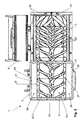
- the Fig. 2 shows the twin-screw extruder 1 in plan view.
- the two juxtaposed parallel juxtaposed extruder screws 22.1, 22.2 are mounted only at a first end 23 on the rear end plate 6 of the elongated extruder housing 2 and have at the opposite second end 24 each have a non-stored, free end module 25, which belongs to the subregion which is in the closed state of hollow cylindrical guide portion of the lower housing part 3 and the housing cover 8 is enclosed.
- the extruder screws 22.1, 22.2 each have a screw pitch, which is smaller from the first end 23 to the beginning of the free end module 25, wherein the free end module 25 has an opposite screw pitch.
- a smaller screw pitch is equivalent to a smaller distance between the webs 26 of the screw flight.
- the inlet funnel 20 in addition to the rectangular, upper inlet opening 21 has a narrower rectangular, lower outlet opening 27, wherein the inlet opening 21 and the outlet opening 27 are connected by two opposite on the longitudinal sides of the extruder housing 2 inwardly sloping funnel walls 28.
- the lower outlet opening 27 is above the extruder screws 22.1, 22.2 and is directed to this, whereby the material to be extruded directly to the extruder screws 22.1, 22.2 can be given.
- the Fig. 3 shows a front view of the twin-screw extruder 1.
- the front end plate 7 has a size-adjustable outlet opening 29 for the metering of the extruded material.
- For a Schieberausnaturalung 30 is provided in the front end plate 7, which extends from the upper edge 31 of the end plate 7 vertically downwards to approximately in the central region of the end plate 7, wherein the Schieberaus Principleung 30 is concavely rounded in the central region.
- the slide recess 30 is covered by a slide fitting 32 of the same shape as the slide recess 30.
- an adjusting spindle 33 is arranged, which can be operated with a crank, wherein the adjusting spindle 33 is connected to the upper end of the slide fitting 32.
- the size of the outlet opening 29 and thus the quantity dosage of the extruded material can be achieved via the vertical sliding movement 34 of the slide fitting 32 within the identical SchieberausEnglishung 30 effected by actuation of the adjusting spindle 33.
- twin-screw extruder 1 is arranged behind the drive module 37, wherein the (not shown) extruder screws 22.1, 22.2 of the twin-screw extruder 1 are driven by the drive module 37.
- the undercarriage 36, on which the twin-screw extruder 1 is mounted, has below the twin-screw extruder 1 two access doors 39 for maintenance.
Landscapes
- Engineering & Computer Science (AREA)
- Mechanical Engineering (AREA)
- Health & Medical Sciences (AREA)
- Life Sciences & Earth Sciences (AREA)
- Chemical & Material Sciences (AREA)
- Wood Science & Technology (AREA)
- Zoology (AREA)
- Organic Chemistry (AREA)
- Bioinformatics & Cheminformatics (AREA)
- Genetics & Genomics (AREA)
- Molecular Biology (AREA)
- General Engineering & Computer Science (AREA)
- Sustainable Development (AREA)
- Biochemistry (AREA)
- Biomedical Technology (AREA)
- General Health & Medical Sciences (AREA)
- Microbiology (AREA)
- Biotechnology (AREA)
- Manufacturing & Machinery (AREA)
- General Chemical & Material Sciences (AREA)
- Oil, Petroleum & Natural Gas (AREA)
- Extrusion Moulding Of Plastics Or The Like (AREA)
- Paper (AREA)
Claims (10)
- Extrudeuse à vis jumelées (1) pour le dépulpage thermomécanique de matières premières organiques et de résidus, comprenant:• un carter d'extrudeuse allongé (2) présentant une partie inférieure du carter (3) avec une section transversale en forme de coupe en U à l'intérieur avec une ouverture (4) étant dirigée vers le haut, s'étendant horizontalement entre une plaque terminale arrière (6) et une plaque terminale avant (7), dans lequel la partie inférieure du carter (3), dans un état fermé, conjointement avec un couvercle du carter (8), présentant une section transversale inversée en forme de coupe en U à l'intérieur avec une ouverture (9) étant dirigée vers le bas, en superposant l'ouverture (4) de la partie inférieure du carter (3) et l'ouverture (9) du couvercle du carter (8), forme une section de guidage en forme de cylindre creux venant en butée contre la plaque terminale avant (7),• deux vis d'extrudeuse (22.1, 22.2) conçues en sens inversé étant agencées l'une à côté de l'autre en parallèle et étant dans chaque cas autoportante, sont montées seulement à une première extrémité (23) sur la plaque terminale arrière (6) du carter d'extrudeuse allongé (2), et à la deuxième extrémité opposée (24) présentent chacune un module terminale libre (25) non monté, dans lequel lesdites vis d'extrudeuse (22.1, 22.2), dans l'état fermé, sont au moins partiellement entourées par la section de guidage en forme de cylindre creux de la partie inférieure du carter (3) et le couvercle du carter (8),dans laquelle la partie inférieure du carter (3) et le couvercle du carter (8) à leur intérieur sont chacun muni d'inserts d'usure (11, 12), ledit insert d'usure (11) de la partie inférieure du carter (3) présentant une section transversale en forme de coupe en U avec des parois latérales courbées vers le haut formant les jambes en forme de U dans la section transversale en forme de coupe en U, et à leurs extrémités supérieures à l'ouverture (4) dans chaque cas étant chanfreinées horizontalement vers l'extérieur en formant des flasques (13), et dans laquelle l'insert d'usure (12) du couvercle du carter (8), dans l'état fermé, présente une section transversale inversée en forme de coupe en U avec deux parois latérales (16) courbées vers le bas formant les jambes en forme de U dans la section transversale inversée en forme de coupe en U dans l'état fermé, et à leurs extrémités inférieures étant chanfreinées horizontalement vers l'extérieur en formant des flasques (14), et dans l'état fermé, en superposant les ouvertures (4, 9), les deux flasques (13) étant chanfreinés vers l'extérieur de la partie inférieure du carter (3) et les flasques (14) étant chanfreinés vers l'extérieur du couvercle du carter (8) prennent contact l'une avec l'autre, caractérisée en ce que les vis d'extrudeuse (22.1, 22.2) présentent chacune un pas de vis devenant plus petit à partir de la première extrémité (23) vers le début du module terminale libre (25), dans lequel un pas de vis plus petit équivaut à une distance plus petite entre les âmes (26) du pas de vis, et dans lequel le module terminale libre (25) présente un pas de vis en sens inversé.
- Extrudeuse à vis jumelées (1) selon la revendication 1, caractérisée en ce que• l'insert d'usure (11) de la partie inférieure du carter (3) présente une paroi de fond plate formant dans la section transversale la section de base en forme de U, et• l'insert d'usure (12) du couvercle du carter (8) présente une paroi de plafond plate (15) formant, dans l'état fermé, la section de base en forme de U dans la section transversale inversée en forme de coupe en U,dans laquelle la paroi de plafond plate (15) et la paroi de fond plate, dans l'état fermé, sont espacées l'une de l'autre en parallèle, et un prisme de guidage (17) est formé respectivement sur la paroi de fond plate de l'insert d'usure (11) et sur la paroi de plafond plate (15) de l'insert d'usure (12) et dans la section transversale présente la forme d'une saillie triangulaire ayant des jambes courbées de façon concave (18) et étant dans chaque cas placées au millieu de la paroi de fond et de la paroi de plafond (15), et s'étendant sur toute la longueur de l'insert d'usure (11, 12) correspondant.
- Extrudeuse à vis jumelées (1) selon la revendication 1 ou 2, caractérisée en ce que les inserts d'usure (11, 12) se composent d'une plaque de soutien flexible étant revêtue d'une couche durcie d'un matériau composite d'armure étant hautement resistant à l'usure.
- Extrudeuse à vis jumelées (1) selon l'une quelconque des revendications 1 à 3, caracterisée en ce qu'une partie supérieure du carter (19) avec une trémie d'alimentation (2) présentant une ouverture d'entrée supérieure (21) et une ouverture de sortie inférieure (27) est pourvue dans une région s'étendant entre la plaque terminale arrière (6) et le couvercle du carter (8), dans laquelle l'ouverture de sortie inférieure (27) de la trémie d'alimentation (20) est agencée au-dessus de et est dirigée vers les vis d'extrudeuse (22.1, 22.2).
- Extrudeuse à vis jumelées (1) selon la revendication 4, caractérisée en ce que les vis d'extrudeuse (22.1, 22.2), dans une région entre la trémis d'alimentation (20) et le couvercle du carter (8), sont recouvertes d'un chanfrein d'entree descendant vers le couvercle du carter (8).
- Extrudeuse à vis jumelées (1) selon l'une quelconque des revendications 1 à 5, caractérisée en ce que la plaque terminale avant (7) présente une ouverture de sortie à taille réglable (29) pour la mésure de la quantité du matériau extrudé, dans laquelle un évidement de glissement (30) émanant à partir d'un bord (31) de la plaque terminale avant (7) est pourvue dans la plaque terminale avant (7), et le réglage de la taille de l'ouverture de sortie (29) peut être realisé par le mouvement glissant (34) d'une pièce de façonnage glissante (32) ayant la même forme que l'évidement de glissement (30) dans l'évidement de glissement (30) par l'intermédiaire d'une broche de réglage (33) étant reliée à la pièce de façonnage glissante (32).
- Dispositif (35) pour le dépulpage thermomécanique de matières premières organiques et de résidus, comprenant:• un cadre de base (36),• un module d'entraînement (37) étant monté sur le cadre de base (36), comprenant deux moteurs à engrenage (38) et deux arbres à cardan pour la transmission de puissance, et deux axes d'extrudeuse étant reliés aux arbres à cardan,• une extrudeuse à vis jumelées (1) selon l'une quelconque des revendications 1 à 6, qui est agencée sur le cadre de base (36) derrière le module d'entraînement (37), dans laquelle les vis d'extrudeuse (22.1, 22.2) de l'extrudeuse à vis jumelées (1) sont entraînées par le module d'entraînement (37),caractérisé en ce que le cadre de base (36), sur lequel l'extrudeuse à vis jumelées (1) est montée, présente des portes d'accès (39) destinèes à l'entretien au-dessous de l'extrudeuse à vis jumelées (1).
- Procédé pour le dépulpage thermomécanique de matières premières organiques et de résidus, dans lequel le matériau à digester est alimenté vers une extrudeuse à vis jumelées (1) dans laquelle le matériau à digester passe par un processus d'extrusion, dans lequel l'extrudeuse à vis jumelées (1) comprend le suivant:• un carter d'extrudeuse allongé (2) présentant une partie inférieure du carter (3) avec une section transversale en forme de coupe en U à l'intérieur avec une ouverture (4) étant dirigée vers le haut, s'étendant horizontalement entre une plaque terminale arrière (6) et une plaque terminale avant (7), dans lequel la partie inférieure du carter (3), dans un état fermé étant présent dans le processus d'extrusion, conjointement avec un couvercle du carter (8) présentant une section transversale inversée en forme de coupe en U à l'intérieur avec une ouverture (9) étant dirigée vers le bas, en superposant l'ouverture (4) de la partie inférieure du carter (3) et l'ouverture (9) du couvercle du carter (8), forme une section de guidage en forme de cylindre creux venant en butée contre la plaque terminale avant (7),• deux vis d'extrudeuse (22.1, 22.2) conçues en sens inversé étant agencées l'une à côté de l'autre en parallèle et étant dans chaque cas autoportante, sont montées seulement à une première extrémité (23) sur la plaque terminale arrière (6) du carter d'extrudeuse allongé (2) et à la deuxième extrémité opposée (24) présentent chacune un module terminale libre (25) non monté, dans lequel lesdites vis d'extrudeuse (22.1, 22.2), dans l'état fermé pendant le processus d'extrusion, sont au moins partiellement entourées par la section de guidage en forme de cylindre creux de la partie inférieure du carter (3) et le couvercle du carter (8),dans laquelle la partie inférieure du carter (3) et le couvercle du carter (8) à l'intérieur sont chacun muni d'inserts d'usure (11, 12), ledit insert d'usure (11) de la partie inférieure du carter (3) présentant une section transversale en forme de coupe en U avec des parois latérales coubées vers le haut formant les jambes en forme de U dans la section transversale en forme de coupe en U et à leurs extrémités supérieures à l'ouverture (4) dans chaque cas étant chanfreinées horizontalement vers l'extérieur en formant de flasques (13), et dans laquelle l'insert d'usure (12) du couvercle du carter (8), dans l'état fermé pendant le processus d'extrusion, présente une section transversale inversée en forme de coupe en U avec deux parois latérales (16) courbées vers le bas formant les jambes en forme de U dans la section transversale inversée en forme de coupe en U dans l'état fermé pendant le processus d'extrusion, et à leurs extrémités inférieures étant chanfreinées horizontalement vers l'extérieur en formant des flasques (14), et dans l'état fermé, en superposant les ouvertures (4, 9), les deux flasques (13) étant chanfreinés vers l'extérieur de la partie inférieure du carter (3) et les flasques (13) étant chanfreinés vers l'éxtérieur du couverture du carter (8) prennent contact l'un avec l'autre, caractérisée en ce que les vis d'extrudeuse (22.1, 22.2) présentent chacune un pas de vis devenant plus petit à partir de la première extrémité (23) vers le début du module terminale libre (25), dans lequel un pas de vis plus petit équivaut à une distance plus petite entre les âmes (26) du pas de vis, et dans lequel le module terminale libre (25) présente un pas de vis en sens inversé.
- Procédé selon la revendication 8, caractérisé en ce que le matériau à extruder passe d'un système externe d'alimentation jusqu'à une trémie d'alimentation (20) mènant directement aux vis d'extrudeuse (22.1, 22.2) en sens inversé, et le flux de matériau étant regulé par une overture de sortie (29) à taille reglable à la plaque terminale avant (7) de l'extrudeuse à vis jumelées (1).
- Procédé selon la revendication 8 ou 9, caractérisé en ce que le matériau à extruder est de la biomasse étant thermomécaniquement digestée avant d'être alimentée jusqu'à un système de fermentation anaérobie pour la production de biogaz.
Priority Applications (1)
| Application Number | Priority Date | Filing Date | Title |
|---|---|---|---|
| PL11160242T PL2371525T5 (pl) | 2010-04-01 | 2011-03-29 | Wytłaczarka dwuślimakowa i sposób termomechanicznego roztwarzania surowców i resztkowych substancji organicznych |
Applications Claiming Priority (1)
| Application Number | Priority Date | Filing Date | Title |
|---|---|---|---|
| DE201010003601 DE102010003601B4 (de) | 2010-04-01 | 2010-04-01 | Doppelschneckenextruder |
Publications (4)
| Publication Number | Publication Date |
|---|---|
| EP2371525A2 EP2371525A2 (fr) | 2011-10-05 |
| EP2371525A3 EP2371525A3 (fr) | 2011-12-07 |
| EP2371525B1 true EP2371525B1 (fr) | 2014-02-12 |
| EP2371525B2 EP2371525B2 (fr) | 2018-01-03 |
Family
ID=44202114
Family Applications (1)
| Application Number | Title | Priority Date | Filing Date |
|---|---|---|---|
| EP11160242.1A Not-in-force EP2371525B2 (fr) | 2010-04-01 | 2011-03-29 | Extrudeuse à deux vis et procédé de fusion thermomécanique de matières brutes et de résidus organiques |
Country Status (3)
| Country | Link |
|---|---|
| EP (1) | EP2371525B2 (fr) |
| DE (1) | DE102010003601B4 (fr) |
| PL (1) | PL2371525T5 (fr) |
Families Citing this family (8)
| Publication number | Priority date | Publication date | Assignee | Title |
|---|---|---|---|---|
| DE102012200167B4 (de) | 2012-01-06 | 2016-07-28 | Thilo Lehmann | Doppelschneckenextruder zum Aufschluss von organischen Rest- und Rohstoffen |
| WO2014117779A2 (fr) * | 2013-01-30 | 2014-08-07 | Xergi Nix Technology A/S | Système de prétraitement de biomasse et procédé correspondant |
| CN109228242B (zh) * | 2018-08-02 | 2020-06-23 | 上海羽迪新材料科技有限公司 | 一种双螺杆挤出机 |
| CN210684012U (zh) * | 2019-09-27 | 2020-06-05 | 苏州比达尔创新材料科技有限公司 | 一种超细纤维挤出装置 |
| CN113021822A (zh) * | 2021-03-26 | 2021-06-25 | 王天寿 | 一种立体网及其生产用双螺杆挤出机 |
| CN114670360B (zh) * | 2022-03-28 | 2023-12-05 | 张家港市五合机械有限公司 | 基于原料测定的自调节粒径的塑料造粒机 |
| CN117400510B (zh) * | 2023-05-12 | 2024-08-30 | 江苏浙标通用零部件股份有限公司 | 一种组合式螺杆装置 |
| CN116855361B (zh) * | 2023-07-14 | 2025-02-11 | 吉林大学 | 同时球磨预处理与微生物发酵的卧式恒温厌氧生物反应器 |
Family Cites Families (14)
| Publication number | Priority date | Publication date | Assignee | Title |
|---|---|---|---|---|
| GB791234A (en) * | 1954-09-29 | 1958-02-26 | Welding Engineers | Mixing and extruding apparatus for thermoplastic materials |
| DE2423785C2 (de) * | 1974-05-16 | 1980-06-12 | Werner & Pfleiderer, 7000 Stuttgart | Verschleißeinsatz für das Schneckengehäuse einer Doppelschneckenstrangpresse oder -Spritzgießmaschine |
| EP0113719B1 (fr) * | 1982-07-16 | 1992-03-11 | Josef Probst | Dispositif pour la production de gaz biologique |
| JPS60176556A (ja) * | 1984-02-24 | 1985-09-10 | Mitsubishi Kakoki Kaisha Ltd | パン粉の製造装置 |
| JPS6283857A (ja) * | 1985-10-08 | 1987-04-17 | Tech Res Assoc Extru Cook Food Ind | 改質小麦粉の製造方法 |
| AT401156B (de) * | 1989-07-12 | 1996-07-25 | Cincinnati Milacron Austria | Schnecke, insbesondere doppelschnecke, für eine schneckenstrangpresse zum verarbeiten von kunststoffen |
| CH685494A5 (de) * | 1993-09-08 | 1995-07-31 | Buehler Ag | Verfahren und Anlage zur Vergärung von Bioabfall. |
| GB2304619A (en) * | 1995-09-09 | 1997-03-26 | Apv Uk Plc | Screw extruders and pressed powder insert components |
| BR9808404A (pt) * | 1997-03-18 | 2000-05-16 | 2B Ag | Processo para aproveitamento de biomassa vegetal e prensa helicoidal para realização desse processo |
| DE102004054468A1 (de) | 2004-11-11 | 2006-05-24 | Rösing, Gerhard, Dr. | Verfahren zur anaeroben Vergärung pflanzlicher Substrate und deren Vorbehandlung mittels thermomechanischem Aufschluss |
| JP2006239729A (ja) † | 2005-03-02 | 2006-09-14 | Mori Machinery Corp | 2軸スクリュー押出し機 |
| DE102007012104A1 (de) | 2007-03-13 | 2008-09-18 | Stirl Anlagentechnik Gmbh | Verfahren zum Hybridaufschluss von lignocellulosehaltiger Biomasse |
| DE202008000161U1 (de) * | 2008-01-04 | 2008-03-13 | Lehmann Maschinenbau Gmbh | Gerätekombination für Intensivaufschluss biogener Stoffe |
| US20120040328A1 (en) * | 2009-01-28 | 2012-02-16 | Michael Niederbacher | Fermenter feed system for fermentable biomass of a biogas system and method for operating the feed system |
-
2010
- 2010-04-01 DE DE201010003601 patent/DE102010003601B4/de not_active Revoked
-
2011
- 2011-03-29 PL PL11160242T patent/PL2371525T5/pl unknown
- 2011-03-29 EP EP11160242.1A patent/EP2371525B2/fr not_active Not-in-force
Also Published As
| Publication number | Publication date |
|---|---|
| EP2371525A2 (fr) | 2011-10-05 |
| EP2371525A3 (fr) | 2011-12-07 |
| EP2371525B2 (fr) | 2018-01-03 |
| PL2371525T3 (pl) | 2014-07-31 |
| PL2371525T5 (pl) | 2018-06-29 |
| DE102010003601A1 (de) | 2011-10-06 |
| DE102010003601B4 (de) | 2015-05-13 |
Similar Documents
| Publication | Publication Date | Title |
|---|---|---|
| EP2371525B1 (fr) | Extrudeuse à deux vis et procédé de fusion thermomécanique de matières brutes et de résidus organiques | |
| WO2007025739A2 (fr) | Melangeur-agitateur pour fermenteur, fermenteur et procede pour actionner un fermenteur | |
| DE4226087A1 (de) | Verfahren zur biologischen Aufbereitung organischer Substanzen, insbesondere zur anaeroben biologischen Hydrolyse zur anschließenden Biomethanisierung und Vorrichtung zur Durchführung des Verfahrens | |
| EP1978086A1 (fr) | Procédé destiné à la dissolution hybride de biomasse contenant de la lignocellulose | |
| DE202010018395U1 (de) | Vorrichtung zur Behandlung von Fest-Flüssig-Gemischen | |
| EP2351824A1 (fr) | Dispositif et procédé destinés à la production de biogaz à partir de matières organiques | |
| EP1756021A1 (fr) | Procede et installation de fermentation pour la fermentation anaerobie de dechets biogenes | |
| EP1987129B1 (fr) | Dispositif de fermentation a transport couple du substrat et des sediments et procede permettant de faire fonctionner ledit dispositif | |
| EP3354718A1 (fr) | Procédé et dispositif destinés a la production de biogaz | |
| EP2243823A2 (fr) | Procédé et dispositif destinés à la production et à la distribution d'énergie | |
| EP1986963B1 (fr) | Procédé et dispositif pour liquéfier en continu des substances organiques solides | |
| DE202010004564U1 (de) | Doppelschneckenextruder zum thermomechanischen Aufschluß von organischen Roh- und Reststoffen | |
| EP1987130B1 (fr) | Dispositif de fermentation et procede de recuperation de biogaz | |
| EP1985692A1 (fr) | Installation de biogaz destinée à la fabrication de biogaz dans un procédé d'écoulement en une étape | |
| EP2730338A2 (fr) | Dispositif de broyage de substrat et paroi de boîtier pour un tel dispositif | |
| DE102007025903A1 (de) | Vorrichtung und Verfahren zur Erzeugung von Biogas durch kontinuierliche Trockenfermentierung stapelbarer Biomasse | |
| DE102004054468A1 (de) | Verfahren zur anaeroben Vergärung pflanzlicher Substrate und deren Vorbehandlung mittels thermomechanischem Aufschluss | |
| EP1013614B1 (fr) | Déshydratation des produits fermentés avec presse à vis sans fin | |
| EP2803729B1 (fr) | Procédé pour la production de biogaz avec fermentation en continu de mélanges de substrat et installation de biogaz destinée à la fermentation en continu de mélanges de substrat | |
| EP2465918B1 (fr) | Fermenteur sec de biomasse doté d'une alimentation et d'une extraction en continu | |
| WO2011035762A1 (fr) | Presse à rouleau | |
| DE10354597B4 (de) | Verfahren zum Erzeugen von Biogas sowie Anlage zum Durchführen dieses Verfahrens | |
| DE102005030980A1 (de) | Verfahren und Anordnung zur Verbesserung der Gasausbeute in Anlagen zur Erzeugung von Biogas | |
| DE102012112086A1 (de) | Ansiedlungseinrichtung für einen Biogasreaktor | |
| DE202007007855U1 (de) | Vorrichtung zur Erzeugung von Biogas durch kontinuierliche Trockenfermentierung stapelbarer Biomasse |
Legal Events
| Date | Code | Title | Description |
|---|---|---|---|
| PUAI | Public reference made under article 153(3) epc to a published international application that has entered the european phase |
Free format text: ORIGINAL CODE: 0009012 |
|
| AK | Designated contracting states |
Kind code of ref document: A2 Designated state(s): AL AT BE BG CH CY CZ DE DK EE ES FI FR GB GR HR HU IE IS IT LI LT LU LV MC MK MT NL NO PL PT RO RS SE SI SK SM TR |
|
| AX | Request for extension of the european patent |
Extension state: BA ME |
|
| PUAL | Search report despatched |
Free format text: ORIGINAL CODE: 0009013 |
|
| AK | Designated contracting states |
Kind code of ref document: A3 Designated state(s): AL AT BE BG CH CY CZ DE DK EE ES FI FR GB GR HR HU IE IS IT LI LT LU LV MC MK MT NL NO PL PT RO RS SE SI SK SM TR |
|
| AX | Request for extension of the european patent |
Extension state: BA ME |
|
| RIC1 | Information provided on ipc code assigned before grant |
Ipc: C12M 1/107 20060101ALI20111101BHEP Ipc: B30B 15/08 20060101AFI20111101BHEP |
|
| 17P | Request for examination filed |
Effective date: 20120305 |
|
| 17Q | First examination report despatched |
Effective date: 20130612 |
|
| GRAP | Despatch of communication of intention to grant a patent |
Free format text: ORIGINAL CODE: EPIDOSNIGR1 |
|
| INTG | Intention to grant announced |
Effective date: 20130903 |
|
| GRAS | Grant fee paid |
Free format text: ORIGINAL CODE: EPIDOSNIGR3 |
|
| GRAA | (expected) grant |
Free format text: ORIGINAL CODE: 0009210 |
|
| AK | Designated contracting states |
Kind code of ref document: B1 Designated state(s): AL AT BE BG CH CY CZ DE DK EE ES FI FR GB GR HR HU IE IS IT LI LT LU LV MC MK MT NL NO PL PT RO RS SE SI SK SM TR |
|
| REG | Reference to a national code |
Ref country code: GB Ref legal event code: FG4D Free format text: NOT ENGLISH |
|
| REG | Reference to a national code |
Ref country code: CH Ref legal event code: EP |
|
| REG | Reference to a national code |
Ref country code: AT Ref legal event code: REF Ref document number: 651948 Country of ref document: AT Kind code of ref document: T Effective date: 20140215 |
|
| REG | Reference to a national code |
Ref country code: IE Ref legal event code: FG4D Free format text: LANGUAGE OF EP DOCUMENT: GERMAN |
|
| REG | Reference to a national code |
Ref country code: DE Ref legal event code: R096 Ref document number: 502011002137 Country of ref document: DE Effective date: 20140327 |
|
| REG | Reference to a national code |
Ref country code: NL Ref legal event code: VDEP Effective date: 20140212 |
|
| REG | Reference to a national code |
Ref country code: LT Ref legal event code: MG4D |
|
| PG25 | Lapsed in a contracting state [announced via postgrant information from national office to epo] |
Ref country code: LT Free format text: LAPSE BECAUSE OF FAILURE TO SUBMIT A TRANSLATION OF THE DESCRIPTION OR TO PAY THE FEE WITHIN THE PRESCRIBED TIME-LIMIT Effective date: 20140212 Ref country code: IS Free format text: LAPSE BECAUSE OF FAILURE TO SUBMIT A TRANSLATION OF THE DESCRIPTION OR TO PAY THE FEE WITHIN THE PRESCRIBED TIME-LIMIT Effective date: 20140612 Ref country code: NO Free format text: LAPSE BECAUSE OF FAILURE TO SUBMIT A TRANSLATION OF THE DESCRIPTION OR TO PAY THE FEE WITHIN THE PRESCRIBED TIME-LIMIT Effective date: 20140512 |
|
| REG | Reference to a national code |
Ref country code: PL Ref legal event code: T3 |
|
| PG25 | Lapsed in a contracting state [announced via postgrant information from national office to epo] |
Ref country code: FI Free format text: LAPSE BECAUSE OF FAILURE TO SUBMIT A TRANSLATION OF THE DESCRIPTION OR TO PAY THE FEE WITHIN THE PRESCRIBED TIME-LIMIT Effective date: 20140212 Ref country code: PT Free format text: LAPSE BECAUSE OF FAILURE TO SUBMIT A TRANSLATION OF THE DESCRIPTION OR TO PAY THE FEE WITHIN THE PRESCRIBED TIME-LIMIT Effective date: 20140612 Ref country code: CY Free format text: LAPSE BECAUSE OF FAILURE TO SUBMIT A TRANSLATION OF THE DESCRIPTION OR TO PAY THE FEE WITHIN THE PRESCRIBED TIME-LIMIT Effective date: 20140212 Ref country code: SE Free format text: LAPSE BECAUSE OF FAILURE TO SUBMIT A TRANSLATION OF THE DESCRIPTION OR TO PAY THE FEE WITHIN THE PRESCRIBED TIME-LIMIT Effective date: 20140212 Ref country code: ES Free format text: LAPSE BECAUSE OF FAILURE TO SUBMIT A TRANSLATION OF THE DESCRIPTION OR TO PAY THE FEE WITHIN THE PRESCRIBED TIME-LIMIT Effective date: 20140212 Ref country code: NL Free format text: LAPSE BECAUSE OF FAILURE TO SUBMIT A TRANSLATION OF THE DESCRIPTION OR TO PAY THE FEE WITHIN THE PRESCRIBED TIME-LIMIT Effective date: 20140212 |
|
| PG25 | Lapsed in a contracting state [announced via postgrant information from national office to epo] |
Ref country code: HR Free format text: LAPSE BECAUSE OF FAILURE TO SUBMIT A TRANSLATION OF THE DESCRIPTION OR TO PAY THE FEE WITHIN THE PRESCRIBED TIME-LIMIT Effective date: 20140212 Ref country code: RS Free format text: LAPSE BECAUSE OF FAILURE TO SUBMIT A TRANSLATION OF THE DESCRIPTION OR TO PAY THE FEE WITHIN THE PRESCRIBED TIME-LIMIT Effective date: 20140212 Ref country code: LV Free format text: LAPSE BECAUSE OF FAILURE TO SUBMIT A TRANSLATION OF THE DESCRIPTION OR TO PAY THE FEE WITHIN THE PRESCRIBED TIME-LIMIT Effective date: 20140212 |
|
| PG25 | Lapsed in a contracting state [announced via postgrant information from national office to epo] |
Ref country code: EE Free format text: LAPSE BECAUSE OF FAILURE TO SUBMIT A TRANSLATION OF THE DESCRIPTION OR TO PAY THE FEE WITHIN THE PRESCRIBED TIME-LIMIT Effective date: 20140212 Ref country code: CZ Free format text: LAPSE BECAUSE OF FAILURE TO SUBMIT A TRANSLATION OF THE DESCRIPTION OR TO PAY THE FEE WITHIN THE PRESCRIBED TIME-LIMIT Effective date: 20140212 Ref country code: DK Free format text: LAPSE BECAUSE OF FAILURE TO SUBMIT A TRANSLATION OF THE DESCRIPTION OR TO PAY THE FEE WITHIN THE PRESCRIBED TIME-LIMIT Effective date: 20140212 Ref country code: RO Free format text: LAPSE BECAUSE OF FAILURE TO SUBMIT A TRANSLATION OF THE DESCRIPTION OR TO PAY THE FEE WITHIN THE PRESCRIBED TIME-LIMIT Effective date: 20140212 |
|
| REG | Reference to a national code |
Ref country code: CH Ref legal event code: PL |
|
| REG | Reference to a national code |
Ref country code: DE Ref legal event code: R026 Ref document number: 502011002137 Country of ref document: DE |
|
| PLBI | Opposition filed |
Free format text: ORIGINAL CODE: 0009260 |
|
| PG25 | Lapsed in a contracting state [announced via postgrant information from national office to epo] |
Ref country code: MC Free format text: LAPSE BECAUSE OF FAILURE TO SUBMIT A TRANSLATION OF THE DESCRIPTION OR TO PAY THE FEE WITHIN THE PRESCRIBED TIME-LIMIT Effective date: 20140212 Ref country code: SK Free format text: LAPSE BECAUSE OF FAILURE TO SUBMIT A TRANSLATION OF THE DESCRIPTION OR TO PAY THE FEE WITHIN THE PRESCRIBED TIME-LIMIT Effective date: 20140212 |
|
| PLAX | Notice of opposition and request to file observation + time limit sent |
Free format text: ORIGINAL CODE: EPIDOSNOBS2 |
|
| 26 | Opposition filed |
Opponent name: LEHMANN-UMT GMBH Effective date: 20141112 |
|
| REG | Reference to a national code |
Ref country code: IE Ref legal event code: MM4A |
|
| PG25 | Lapsed in a contracting state [announced via postgrant information from national office to epo] |
Ref country code: CH Free format text: LAPSE BECAUSE OF NON-PAYMENT OF DUE FEES Effective date: 20140331 Ref country code: IE Free format text: LAPSE BECAUSE OF NON-PAYMENT OF DUE FEES Effective date: 20140329 Ref country code: LI Free format text: LAPSE BECAUSE OF NON-PAYMENT OF DUE FEES Effective date: 20140331 |
|
| REG | Reference to a national code |
Ref country code: DE Ref legal event code: R026 Ref document number: 502011002137 Country of ref document: DE Effective date: 20141112 |
|
| PLBB | Reply of patent proprietor to notice(s) of opposition received |
Free format text: ORIGINAL CODE: EPIDOSNOBS3 |
|
| PG25 | Lapsed in a contracting state [announced via postgrant information from national office to epo] |
Ref country code: SI Free format text: LAPSE BECAUSE OF FAILURE TO SUBMIT A TRANSLATION OF THE DESCRIPTION OR TO PAY THE FEE WITHIN THE PRESCRIBED TIME-LIMIT Effective date: 20140212 |
|
| GBPC | Gb: european patent ceased through non-payment of renewal fee |
Effective date: 20150329 |
|
| PG25 | Lapsed in a contracting state [announced via postgrant information from national office to epo] |
Ref country code: GB Free format text: LAPSE BECAUSE OF NON-PAYMENT OF DUE FEES Effective date: 20150329 |
|
| PG25 | Lapsed in a contracting state [announced via postgrant information from national office to epo] |
Ref country code: MT Free format text: LAPSE BECAUSE OF FAILURE TO SUBMIT A TRANSLATION OF THE DESCRIPTION OR TO PAY THE FEE WITHIN THE PRESCRIBED TIME-LIMIT Effective date: 20140212 |
|
| REG | Reference to a national code |
Ref country code: FR Ref legal event code: PLFP Year of fee payment: 6 |
|
| PG25 | Lapsed in a contracting state [announced via postgrant information from national office to epo] |
Ref country code: SM Free format text: LAPSE BECAUSE OF FAILURE TO SUBMIT A TRANSLATION OF THE DESCRIPTION OR TO PAY THE FEE WITHIN THE PRESCRIBED TIME-LIMIT Effective date: 20140212 |
|
| PG25 | Lapsed in a contracting state [announced via postgrant information from national office to epo] |
Ref country code: BG Free format text: LAPSE BECAUSE OF FAILURE TO SUBMIT A TRANSLATION OF THE DESCRIPTION OR TO PAY THE FEE WITHIN THE PRESCRIBED TIME-LIMIT Effective date: 20140212 Ref country code: GR Free format text: LAPSE BECAUSE OF FAILURE TO SUBMIT A TRANSLATION OF THE DESCRIPTION OR TO PAY THE FEE WITHIN THE PRESCRIBED TIME-LIMIT Effective date: 20140513 |
|
| PG25 | Lapsed in a contracting state [announced via postgrant information from national office to epo] |
Ref country code: BE Free format text: LAPSE BECAUSE OF FAILURE TO SUBMIT A TRANSLATION OF THE DESCRIPTION OR TO PAY THE FEE WITHIN THE PRESCRIBED TIME-LIMIT Effective date: 20140331 Ref country code: TR Free format text: LAPSE BECAUSE OF FAILURE TO SUBMIT A TRANSLATION OF THE DESCRIPTION OR TO PAY THE FEE WITHIN THE PRESCRIBED TIME-LIMIT Effective date: 20140212 Ref country code: HU Free format text: LAPSE BECAUSE OF FAILURE TO SUBMIT A TRANSLATION OF THE DESCRIPTION OR TO PAY THE FEE WITHIN THE PRESCRIBED TIME-LIMIT; INVALID AB INITIO Effective date: 20110329 Ref country code: LU Free format text: LAPSE BECAUSE OF NON-PAYMENT OF DUE FEES Effective date: 20140329 |
|
| REG | Reference to a national code |
Ref country code: FR Ref legal event code: PLFP Year of fee payment: 7 |
|
| PUAH | Patent maintained in amended form |
Free format text: ORIGINAL CODE: 0009272 |
|
| STAA | Information on the status of an ep patent application or granted ep patent |
Free format text: STATUS: PATENT MAINTAINED AS AMENDED |
|
| 27A | Patent maintained in amended form |
Effective date: 20180103 |
|
| AK | Designated contracting states |
Kind code of ref document: B2 Designated state(s): AL AT BE BG CH CY CZ DE DK EE ES FI FR GB GR HR HU IE IS IT LI LT LU LV MC MK MT NL NO PL PT RO RS SE SI SK SM TR |
|
| REG | Reference to a national code |
Ref country code: DE Ref legal event code: R102 Ref document number: 502011002137 Country of ref document: DE |
|
| REG | Reference to a national code |
Ref country code: FR Ref legal event code: PLFP Year of fee payment: 8 |
|
| PGFP | Annual fee paid to national office [announced via postgrant information from national office to epo] |
Ref country code: DE Payment date: 20180322 Year of fee payment: 8 |
|
| PGFP | Annual fee paid to national office [announced via postgrant information from national office to epo] |
Ref country code: AT Payment date: 20180320 Year of fee payment: 8 Ref country code: FR Payment date: 20180326 Year of fee payment: 8 Ref country code: IT Payment date: 20180322 Year of fee payment: 8 |
|
| PG25 | Lapsed in a contracting state [announced via postgrant information from national office to epo] |
Ref country code: MK Free format text: LAPSE BECAUSE OF FAILURE TO SUBMIT A TRANSLATION OF THE DESCRIPTION OR TO PAY THE FEE WITHIN THE PRESCRIBED TIME-LIMIT Effective date: 20140212 |
|
| PGFP | Annual fee paid to national office [announced via postgrant information from national office to epo] |
Ref country code: PL Payment date: 20180322 Year of fee payment: 8 |
|
| PG25 | Lapsed in a contracting state [announced via postgrant information from national office to epo] |
Ref country code: AL Free format text: LAPSE BECAUSE OF FAILURE TO SUBMIT A TRANSLATION OF THE DESCRIPTION OR TO PAY THE FEE WITHIN THE PRESCRIBED TIME-LIMIT Effective date: 20140212 |
|
| REG | Reference to a national code |
Ref country code: DE Ref legal event code: R119 Ref document number: 502011002137 Country of ref document: DE |
|
| REG | Reference to a national code |
Ref country code: AT Ref legal event code: MM01 Ref document number: 651948 Country of ref document: AT Kind code of ref document: T Effective date: 20190329 |
|
| PG25 | Lapsed in a contracting state [announced via postgrant information from national office to epo] |
Ref country code: AT Free format text: LAPSE BECAUSE OF NON-PAYMENT OF DUE FEES Effective date: 20190329 Ref country code: DE Free format text: LAPSE BECAUSE OF NON-PAYMENT OF DUE FEES Effective date: 20191001 |
|
| PG25 | Lapsed in a contracting state [announced via postgrant information from national office to epo] |
Ref country code: FR Free format text: LAPSE BECAUSE OF NON-PAYMENT OF DUE FEES Effective date: 20190331 Ref country code: IT Free format text: LAPSE BECAUSE OF NON-PAYMENT OF DUE FEES Effective date: 20190329 |
|
| PG25 | Lapsed in a contracting state [announced via postgrant information from national office to epo] |
Ref country code: PL Free format text: LAPSE BECAUSE OF NON-PAYMENT OF DUE FEES Effective date: 20190329 |