EP2371560B1 - Imprimante - Google Patents
Imprimante Download PDFInfo
- Publication number
- EP2371560B1 EP2371560B1 EP08879134A EP08879134A EP2371560B1 EP 2371560 B1 EP2371560 B1 EP 2371560B1 EP 08879134 A EP08879134 A EP 08879134A EP 08879134 A EP08879134 A EP 08879134A EP 2371560 B1 EP2371560 B1 EP 2371560B1
- Authority
- EP
- European Patent Office
- Prior art keywords
- unit
- holding mechanism
- carriage
- moved
- unit holding
- Prior art date
- Legal status (The legal status is an assumption and is not a legal conclusion. Google has not performed a legal analysis and makes no representation as to the accuracy of the status listed.)
- Not-in-force
Links
- 230000007246 mechanism Effects 0.000 claims description 114
- 230000002093 peripheral effect Effects 0.000 claims description 24
- 238000007639 printing Methods 0.000 description 91
- 238000012423 maintenance Methods 0.000 description 34
- 239000000976 ink Substances 0.000 description 20
- 239000003086 colorant Substances 0.000 description 17
- 230000000694 effects Effects 0.000 description 4
- 238000003780 insertion Methods 0.000 description 3
- 230000037431 insertion Effects 0.000 description 3
- 238000004519 manufacturing process Methods 0.000 description 3
- 239000001041 dye based ink Substances 0.000 description 1
- 239000000463 material Substances 0.000 description 1
- 239000001042 pigment based ink Substances 0.000 description 1
Images


Classifications
-
- B—PERFORMING OPERATIONS; TRANSPORTING
- B41—PRINTING; LINING MACHINES; TYPEWRITERS; STAMPS
- B41J—TYPEWRITERS; SELECTIVE PRINTING MECHANISMS, i.e. MECHANISMS PRINTING OTHERWISE THAN FROM A FORME; CORRECTION OF TYPOGRAPHICAL ERRORS
- B41J3/00—Typewriters or selective printing or marking mechanisms characterised by the purpose for which they are constructed
- B41J3/54—Typewriters or selective printing or marking mechanisms characterised by the purpose for which they are constructed with two or more sets of type or printing elements
-
- B—PERFORMING OPERATIONS; TRANSPORTING
- B41—PRINTING; LINING MACHINES; TYPEWRITERS; STAMPS
- B41J—TYPEWRITERS; SELECTIVE PRINTING MECHANISMS, i.e. MECHANISMS PRINTING OTHERWISE THAN FROM A FORME; CORRECTION OF TYPOGRAPHICAL ERRORS
- B41J11/00—Devices or arrangements of selective printing mechanisms, e.g. ink-jet printers or thermal printers, for supporting or handling copy material in sheet or web form
- B41J11/66—Applications of cutting devices
- B41J11/70—Applications of cutting devices cutting perpendicular to the direction of paper feed
- B41J11/706—Applications of cutting devices cutting perpendicular to the direction of paper feed using a cutting tool mounted on a reciprocating carrier
-
- B—PERFORMING OPERATIONS; TRANSPORTING
- B41—PRINTING; LINING MACHINES; TYPEWRITERS; STAMPS
- B41J—TYPEWRITERS; SELECTIVE PRINTING MECHANISMS, i.e. MECHANISMS PRINTING OTHERWISE THAN FROM A FORME; CORRECTION OF TYPOGRAPHICAL ERRORS
- B41J3/00—Typewriters or selective printing or marking mechanisms characterised by the purpose for which they are constructed
- B41J3/54—Typewriters or selective printing or marking mechanisms characterised by the purpose for which they are constructed with two or more sets of type or printing elements
- B41J3/543—Typewriters or selective printing or marking mechanisms characterised by the purpose for which they are constructed with two or more sets of type or printing elements with multiple inkjet print heads
Definitions
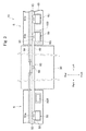
- Fig. 3 is a plan view showing a vicinity of the guide rail of the printer apparatus.
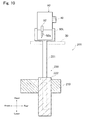
- Fig. 9 is a side view showing the vertically moving mechanism (lower side moved state) in accordance with the second embodiment.
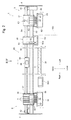
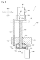
- the ball screw shaft 130 is a screw shaft which is formed with a male screw part (not shown) on its outer peripheral face and extended in the upper and lower direction and its upper end part is attached to an under face of the left standby station 95L. Further, the ball screw shaft 130 is inserted into the ball screw shaft hole 111 so as to be capable of moving vertically (upper and lower direction) and the outer peripheral face (male screw part) of the ball screw shaft 130 is fitted with the inner peripheral face (female screw part) of the ball screw gear 131 in the gear housing chamber 113.
- the vertically drive motor 120 is controlled so as to be driven and rotated by the controller to rotatably drive the ball screw gear 131 through a drive gear 122 which is attached to an output shaft 121.
- the guide member 101 is inserted into the guide hole 112 of the fixed support base 110 so as to be capable of moving in a vertical direction.
- a vertically moving mechanism 150 will be described below with reference to Figs. 8 and 9 as another embodiment of the vertically moving mechanism 100 in the printer apparatus 1 in accordance with the first embodiment.
- the same reference numbers are used for the members described in the first embodiment and their descriptions are omitted.
- Fig. 8 shows a state that the cutting unit 90 is held by the left standby station 95L and
- Fig. 9 shows a state that the cutting unit 90 has been moved down and retreated respectively.
- the manufacturing cost of the printer apparatus 1 can be reduced in total.
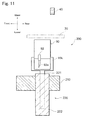
- a vertically moving mechanism 250 will be described below with reference to Fig. 12 as another embodiment of the vertically moving mechanism 100 in the printer apparatus 1 in accordance with the first embodiment.
- the same reference numbers are used for the members described in the first embodiment and their descriptions are omitted.
- Fig. 12 a state where the cutting unit 90 is held by the left standby station 95L is shown by the solid line and a state where the cutting unit 90 has been moved down and retreated is shown by the dotted line respectively.
Landscapes
- Handling Of Sheets (AREA)
- Ink Jet (AREA)
Claims (8)
- Dispositif formant imprimante (1) comprenant :un rail de guidage (40) qui fait face à un moyen de retenue de médium (30) destiné à supporter un objet formant médium (8), peut être déplacé relativement dans une direction d'alimentation prédéterminée par rapport à l'objet formant médium lorsqu'il est supporté par le moyen de retenue de médium (30), et s'étend suivant une direction de balayage perpendiculaire à la direction d'alimentation prédéterminée ;une première unité (50) qui comporte un premier chariot (85) qui peut être déplacé dans la direction de balayage le long du rail de guidage (40) et un premier dispositif opérationnel (30) qui est monté sur le premier chariot (85) afin d'exécuter une opération prédéterminée sur l'objet formant médium (8) ;une seconde unité (60) qui comporte un second chariot (61) qui peut être déplacé dans la direction de balayage le long du rail de guidage (40) et un second dispositif opérationnel (62) qui est monté sur le second chariot (61) afin d'exécuter une opération prédéterminée sur l'objet formant médium ;un premier mécanisme de retenue d'unité qui est formé sur un côté dans la direction de balayage par rapport au moyen de retenue de médium (30) et permet de retenir la première unité (50) ;un second mécanisme de retenue d'unité qui est formé entre le moyen de retenue de médium (30) et le premier mécanisme de retenue d'unité dans la direction de balayage et permet de retenir la seconde unité (60) ; etun mécanisme de retrait vertical (100) qui est structuré de telle sorte que la seconde unité (60) retenue par le second mécanisme de retenue d'unité et le second mécanisme de retenue d'unité peuvent être déplacés ensemble vers le haut et vers le bas par rapport au moyen de retenue de médium (30) ;dans lequel lorsque la retenue de la première unité (50) par le premier mécanisme de retenue d'unité doit être arrêtée afin d'exécuter une opération prédéterminée alors que le premier dispositif opérationnel est déplacé dans la direction du balayage, la seconde unité (60) et le second mécanisme de retenue d'unité sont déplacés par le mécanisme de retrait vertical (100) de manière à être positionnés sur un côté inférieur par rapport au moyen de retenue de médium (30).
- Dispositif formant imprimante selon la revendication 1, dans lequel
la première unité est une unité de tête qui comporte un chariot de tête qui peut être déplacé dans la direction de balayage le long du rail de guidage et une tête d'impression qui est montée sur le chariot de tête et à partir de laquelle de l'encre est éjectée vers l'objet formant médium, et
la seconde unité est une unité de découpe qui comporte un chariot de coupe qui peut être déplacé dans la direction de balayage le long du rail de guidage et un dispositif de coupe qui est monté sur le chariot de coupe afin d'exécuter une opération de coupe sur l'objet formant médium suivant une forme prédéterminée. - Dispositif formant imprimante selon la revendication 1, dans lequel
la première unité est une unité de découpe qui comporte un chariot de coupe qui peut être déplacé dans la direction de balayage le long du rail de guidage et un dispositif de coupe qui est monté sur le chariot de coupe afin d'exécuter une opération de coupe sur l'objet formant médium suivant une forme prédéterminée, et
la seconde unité est une unité de tête qui comporte un chariot de tête qui peut être déplacé dans la direction de balayage le long du rail de guidage et une tête d'impression qui est montée sur le chariot de tête et à partir de laquelle de l'encre est éjectée sur l'objet formant médium. - Dispositif formant imprimante selon la revendication 1, dans lequel chacune des première et seconde unités est une unité de tête qui comporte un chariot de tête qui peut être déplacé dans la direction de balayage le long du rail de guidage et une tête d'impression qui est montée sur le chariot de tête et à partir de laquelle de l'encre est éjectée vers l'objet formant médium.
- Dispositif formant imprimante selon l'une des revendications 1 à 4, dans lequel le mécanisme de retrait vertical comporte :un arbre rainuré dont la face périphérique externe comporte une partie de rainure en spirale et qui s'étend verticalement et est fixé sur le second mécanisme de retenue d'unité,un élément de rotation assemblé dont la face périphérique interne comporte une partie de rainure en spirale pouvant être assemblée sur la face périphérique externe de l'arbre rainuré et qui est reçu à l'intérieur d'une partie de retenue fixe formée sur un côté inférieur du second mécanisme de retenue d'unité dans un état supporté de manière à pouvoir tourner dans un plan horizontal de telle sorte que la face périphérique interne est assemblée à la face périphérique externe de l'arbre rainuré afin de supporter l'arbre rainuré, etun moteur d'entraînement qui permet d'entraîner en rotation l'élément de rotation assemblé,et un effort est appliqué vers le haut et vers le bas sur l'arbre rainuré qui est assemblé sur l'élément de rotation assemblé au moyen duquel le moteur d'entraînement est entraîné en rotation afin de faire tourner l'élément de rotation assemblé de telle sorte que le second mécanisme de retenue d'unité et la seconde unité sont déplacés verticalement par rapport à la partie de retenue fixe.
- Dispositif formant imprimante selon l'une des revendications 1 à 4, dans lequel le mécanisme de retrait vertical comporte ;
un dispositif de transfert vertical qui reçoit un arbre rainuré dont la face périphérique externe comporte une partie de rainure en spirale de manière à s'étendre verticalement, qui supporte avec liberté de rotation l'arbre rainuré, et qui est fixé sur une partie de retenue fixe formée sur une face inférieure du second mécanisme de retenue d'unité,
un élément de retenue mobile qui est fixé sur le second mécanisme de retenue d'unité afin de supporter le second mécanisme de retenue d'unité et, dans lequel une partie assemblée qui comporte une partie de rainure en spirale pouvant s'assembler sur la face périphérique externe de l'arbre rainuré est assemblée sur l'arbre rainuré de manière à pouvoir être déplacée verticalement par rapport au dispositif de transfert vertical, et
un moteur d'entraînement qui permet d'entraîner en rotation l'arbre rainuré, et un effort est appliqué vers le haut et vers le bas de l'élément de retenue mobile qui est assemblé sur l'arbre rainuré au moyen duquel le moteur d'entraînement est entraîné en rotation de manière à faire tourner l'arbre rainuré de telle sorte que le second mécanisme de retenue d'unité et la seconde unité sont déplacés verticalement par rapport à la partie de retenue fixe. - Dispositif formant imprimante selon l'une des revendications 1 à 4, dans lequel
le mécanisme de retrait vertical comporte un dispositif à piston dont une extrémité est fixée sur une partie de retenue fixe formée sur un côté inférieur du second mécanisme de retenue d'unité et dont l'autre extrémité est fixée sur le second mécanisme de retenue d'unité, le dispositif à piston étant disposé de manière à pouvoir être étendu et rétracté vers le haut et vers le bas, et
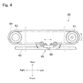
le second mécanisme de retenue d'unité et la seconde unité sont déplacés verticalement par rapport à la partie de retenue fixe par le dispositif à piston qui est étendu et rétracté. - Dispositif formant imprimante selon l'une des revendications 1 à 4, dans lequel le mécanisme de retrait vertical comporte :une paire de poulies qui sont agencées à une position supérieure et une position inférieure,un tapis de transfert sans fin qui est tendu sur une paire de poulies de manière à être étendu vers le haut et vers le bas et couplé au second mécanisme de retenue d'unité, etun moteur d'entraînement qui permet d'entraîner en rotation l'une de la paire de poulies, etle tapis de transfert sans fin tendu sur la paire de poulies est déplacé vers le haut et vers le bas par le moteur d'entraînement qui est entraîné en rotation de telle sorte que le second mécanisme de retenue d'unité et la seconde unité sont déplacés verticalement par rapport à la paire de poulies.
Applications Claiming Priority (1)
| Application Number | Priority Date | Filing Date | Title |
|---|---|---|---|
| PCT/JP2008/073586 WO2010073338A1 (fr) | 2008-12-25 | 2008-12-25 | Imprimante |
Publications (3)
| Publication Number | Publication Date |
|---|---|
| EP2371560A1 EP2371560A1 (fr) | 2011-10-05 |
| EP2371560A4 EP2371560A4 (fr) | 2011-10-05 |
| EP2371560B1 true EP2371560B1 (fr) | 2012-05-16 |
Family
ID=42287006
Family Applications (1)
| Application Number | Title | Priority Date | Filing Date |
|---|---|---|---|
| EP08879134A Not-in-force EP2371560B1 (fr) | 2008-12-25 | 2008-12-25 | Imprimante |
Country Status (6)
| Country | Link |
|---|---|
| US (1) | US8192097B2 (fr) |
| EP (1) | EP2371560B1 (fr) |
| JP (1) | JP5143915B2 (fr) |
| KR (1) | KR101239860B1 (fr) |
| CN (1) | CN102066117B (fr) |
| WO (1) | WO2010073338A1 (fr) |
Families Citing this family (12)
| Publication number | Priority date | Publication date | Assignee | Title |
|---|---|---|---|---|
| JP5760694B2 (ja) * | 2011-05-26 | 2015-08-12 | セイコーエプソン株式会社 | 液体吐出装置 |
| JP5854198B2 (ja) * | 2011-09-09 | 2016-02-09 | 株式会社リコー | 画像形成装置及び記録媒体 |
| JP5862182B2 (ja) * | 2011-10-12 | 2016-02-16 | 株式会社リコー | 画像形成装置 |
| CN105224975B (zh) * | 2015-08-28 | 2018-07-20 | 河北汇金机电股份有限公司 | 一种纸币清分流水线及纸币管理方法 |
| JP7056100B2 (ja) * | 2017-11-29 | 2022-04-19 | セイコーエプソン株式会社 | キャリッジ移動機構、及び液体吐出装置 |
| JP7277078B2 (ja) * | 2018-03-29 | 2023-05-18 | キヤノン株式会社 | インクジェット記録装置 |
| CN108927995A (zh) * | 2018-04-27 | 2018-12-04 | 合肥海闻自动化设备有限公司 | 一种用于袖子便携式工业数字打印的平台机构 |
| KR101985413B1 (ko) | 2018-06-14 | 2019-06-03 | 에이에스티엔지니어링(주) | 버티컬 복층 베이킹 챔버장치 |
| KR102083031B1 (ko) | 2019-03-25 | 2020-04-23 | 김용태 | 베이퍼 챔버 접합 방법 및 그 구조 |
| JP7669673B2 (ja) * | 2020-11-30 | 2025-04-30 | ブラザー工業株式会社 | 印刷装置 |
| CN114590037A (zh) * | 2022-03-11 | 2022-06-07 | 洛阳环升建筑科技有限公司 | 一种移动喷码装置 |
| CN116118365B (zh) * | 2023-02-03 | 2024-01-26 | 北京中程志远科技有限公司 | 一种促墨干燥的打印机 |
Family Cites Families (15)
| Publication number | Priority date | Publication date | Assignee | Title |
|---|---|---|---|---|
| JP3333312B2 (ja) * | 1994-03-24 | 2002-10-15 | ローランドディー.ジー.株式会社 | 画像作成および切り抜き装置 |
| JP2773725B2 (ja) * | 1996-01-09 | 1998-07-09 | 日本電気株式会社 | シリアル記録装置 |
| JPH09240097A (ja) * | 1996-03-08 | 1997-09-16 | Canon Inc | 走査型キャリアを備える機器およびプリント装置 |
| JP3245359B2 (ja) * | 1996-07-30 | 2002-01-15 | キヤノン株式会社 | 画像記録装置 |
| JPH1071710A (ja) * | 1996-08-30 | 1998-03-17 | Oki Data:Kk | インクジェットプリンタ |
| JPH1076729A (ja) * | 1996-09-03 | 1998-03-24 | Shinko Seisakusho Co Ltd | プリンタ |
| JP2000218884A (ja) * | 1999-02-02 | 2000-08-08 | Canon Inc | 記録装置 |
| JP2005297248A (ja) | 2004-04-07 | 2005-10-27 | Roland Dg Corp | 画像作成および切り抜き装置 |
| JP4241639B2 (ja) * | 2005-02-14 | 2009-03-18 | セイコーエプソン株式会社 | 液滴吐出装置及び液滴吐出ヘッドの保守方法 |
| JP2006341420A (ja) * | 2005-06-08 | 2006-12-21 | Roland Dg Corp | 画像作成および切り抜き装置 |
| JP2007030253A (ja) * | 2005-07-25 | 2007-02-08 | Canon Inc | インクジェット記録装置 |
| JP4879181B2 (ja) * | 2005-08-31 | 2012-02-22 | 平田機工株式会社 | ワークハンドリング装置 |
| JP4529929B2 (ja) * | 2006-03-27 | 2010-08-25 | ブラザー工業株式会社 | インクジェット記録装置 |
| JP4909785B2 (ja) * | 2007-03-28 | 2012-04-04 | 株式会社ミマキエンジニアリング | プリンタ/プロッタ装置 |
| JP4990001B2 (ja) * | 2007-03-30 | 2012-08-01 | 株式会社ミマキエンジニアリング | プリンタ・プロッタ装置 |
-
2008
- 2008-12-25 KR KR1020107027482A patent/KR101239860B1/ko not_active Expired - Fee Related
- 2008-12-25 EP EP08879134A patent/EP2371560B1/fr not_active Not-in-force
- 2008-12-25 CN CN200880129859.5A patent/CN102066117B/zh not_active Expired - Fee Related
- 2008-12-25 JP JP2010543676A patent/JP5143915B2/ja active Active
- 2008-12-25 WO PCT/JP2008/073586 patent/WO2010073338A1/fr not_active Ceased
-
2010
- 2010-11-30 US US12/955,934 patent/US8192097B2/en active Active
Also Published As
| Publication number | Publication date |
|---|---|
| JPWO2010073338A1 (ja) | 2012-05-31 |
| KR20110015612A (ko) | 2011-02-16 |
| US8192097B2 (en) | 2012-06-05 |
| JP5143915B2 (ja) | 2013-02-13 |
| EP2371560A1 (fr) | 2011-10-05 |
| EP2371560A4 (fr) | 2011-10-05 |
| US20110103870A1 (en) | 2011-05-05 |
| CN102066117B (zh) | 2014-04-30 |
| CN102066117A (zh) | 2011-05-18 |
| WO2010073338A1 (fr) | 2010-07-01 |
| KR101239860B1 (ko) | 2013-03-06 |
Similar Documents
| Publication | Publication Date | Title |
|---|---|---|
| EP2371560B1 (fr) | Imprimante | |
| US7948650B2 (en) | Printer-plotter | |
| US8721067B2 (en) | Printer apparatus | |
| US8272733B2 (en) | Printer apparatus | |
| JP7000288B2 (ja) | インクジェットプリンタおよびカッティングヘッド付きインクジェットプリンタ | |
| US8262214B2 (en) | Ink jet printer | |
| JP7628672B2 (ja) | インクジェットプリンタ | |
| US8267508B2 (en) | Ink jet printer | |
| WO2010035780A1 (fr) | Traceur électrostatique | |
| US8277038B2 (en) | Ink jet printer | |
| US8794740B2 (en) | Ink jet recording apparatus | |
| JPH1158877A (ja) | ドットマトリックスプリンタ及びその製造方法 | |
| JP2001162872A (ja) | 印刷方法並びにインクジェットプリンタおよびこれに用いるテープカートリッジ | |
| JP2011218813A (ja) | 印刷装置、印刷方法及び印刷物の製造方法 | |
| JP2001163512A (ja) | インクジェットプリンタ | |
| JP2011201324A (ja) | インクジェットヘッドユニット、印刷装置、印刷方法、および印刷物を製造する方法 | |
| JP2010280220A (ja) | 印刷装置 | |
| JPH03146357A (ja) | プリンタ | |
| JP2005280977A (ja) | 液体噴射装置 | |
| JP2001162883A (ja) | インクジェットプリンタ | |
| JP2006095979A (ja) | 記録装置 | |
| JP2005028701A (ja) | 記録媒体切断装置及び記録装置 | |
| JP2011136582A (ja) | 印刷装置 | |
| JP2000272147A (ja) | インクジェットヘッドのメンテナンス機構 |
Legal Events
| Date | Code | Title | Description |
|---|---|---|---|
| PUAI | Public reference made under article 153(3) epc to a published international application that has entered the european phase |
Free format text: ORIGINAL CODE: 0009012 |
|
| 17P | Request for examination filed |
Effective date: 20101117 |
|
| A4 | Supplementary search report drawn up and despatched |
Effective date: 20110318 |
|
| AK | Designated contracting states |
Kind code of ref document: A1 Designated state(s): AT BE BG CH CY CZ DE DK EE ES FI FR GB GR HR HU IE IS IT LI LT LU LV MC MT NL NO PL PT RO SE SI SK TR |
|
| GRAP | Despatch of communication of intention to grant a patent |
Free format text: ORIGINAL CODE: EPIDOSNIGR1 |
|
| RIC1 | Information provided on ipc code assigned before grant |
Ipc: B41J 3/54 20060101AFI20111125BHEP Ipc: B41J 11/70 20060101ALI20111125BHEP |
|
| GRAS | Grant fee paid |
Free format text: ORIGINAL CODE: EPIDOSNIGR3 |
|
| DAX | Request for extension of the european patent (deleted) | ||
| GRAA | (expected) grant |
Free format text: ORIGINAL CODE: 0009210 |
|
| RAP1 | Party data changed (applicant data changed or rights of an application transferred) |
Owner name: MIMAKI ENGINEERING CO., LTD. |
|
| AK | Designated contracting states |
Kind code of ref document: B1 Designated state(s): AT BE BG CH CY CZ DE DK EE ES FI FR GB GR HR HU IE IS IT LI LT LU LV MC MT NL NO PL PT RO SE SI SK TR |
|
| REG | Reference to a national code |
Ref country code: GB Ref legal event code: FG4D |
|
| REG | Reference to a national code |
Ref country code: CH Ref legal event code: EP |
|
| REG | Reference to a national code |
Ref country code: AT Ref legal event code: REF Ref document number: 557894 Country of ref document: AT Kind code of ref document: T Effective date: 20120615 |
|
| REG | Reference to a national code |
Ref country code: IE Ref legal event code: FG4D |
|
| REG | Reference to a national code |
Ref country code: DE Ref legal event code: R096 Ref document number: 602008015768 Country of ref document: DE Effective date: 20120712 |
|
| REG | Reference to a national code |
Ref country code: NL Ref legal event code: VDEP Effective date: 20120516 |
|
| REG | Reference to a national code |
Ref country code: LT Ref legal event code: MG4D Effective date: 20120516 |
|
| PG25 | Lapsed in a contracting state [announced via postgrant information from national office to epo] |
Ref country code: SE Free format text: LAPSE BECAUSE OF FAILURE TO SUBMIT A TRANSLATION OF THE DESCRIPTION OR TO PAY THE FEE WITHIN THE PRESCRIBED TIME-LIMIT Effective date: 20120516 Ref country code: NO Free format text: LAPSE BECAUSE OF FAILURE TO SUBMIT A TRANSLATION OF THE DESCRIPTION OR TO PAY THE FEE WITHIN THE PRESCRIBED TIME-LIMIT Effective date: 20120816 Ref country code: CY Free format text: LAPSE BECAUSE OF FAILURE TO SUBMIT A TRANSLATION OF THE DESCRIPTION OR TO PAY THE FEE WITHIN THE PRESCRIBED TIME-LIMIT Effective date: 20120516 Ref country code: PL Free format text: LAPSE BECAUSE OF FAILURE TO SUBMIT A TRANSLATION OF THE DESCRIPTION OR TO PAY THE FEE WITHIN THE PRESCRIBED TIME-LIMIT Effective date: 20120516 Ref country code: LT Free format text: LAPSE BECAUSE OF FAILURE TO SUBMIT A TRANSLATION OF THE DESCRIPTION OR TO PAY THE FEE WITHIN THE PRESCRIBED TIME-LIMIT Effective date: 20120516 Ref country code: IS Free format text: LAPSE BECAUSE OF FAILURE TO SUBMIT A TRANSLATION OF THE DESCRIPTION OR TO PAY THE FEE WITHIN THE PRESCRIBED TIME-LIMIT Effective date: 20120916 Ref country code: FI Free format text: LAPSE BECAUSE OF FAILURE TO SUBMIT A TRANSLATION OF THE DESCRIPTION OR TO PAY THE FEE WITHIN THE PRESCRIBED TIME-LIMIT Effective date: 20120516 |
|
| REG | Reference to a national code |
Ref country code: AT Ref legal event code: MK05 Ref document number: 557894 Country of ref document: AT Kind code of ref document: T Effective date: 20120516 |
|
| PG25 | Lapsed in a contracting state [announced via postgrant information from national office to epo] |
Ref country code: PT Free format text: LAPSE BECAUSE OF FAILURE TO SUBMIT A TRANSLATION OF THE DESCRIPTION OR TO PAY THE FEE WITHIN THE PRESCRIBED TIME-LIMIT Effective date: 20120917 Ref country code: GR Free format text: LAPSE BECAUSE OF FAILURE TO SUBMIT A TRANSLATION OF THE DESCRIPTION OR TO PAY THE FEE WITHIN THE PRESCRIBED TIME-LIMIT Effective date: 20120817 Ref country code: LV Free format text: LAPSE BECAUSE OF FAILURE TO SUBMIT A TRANSLATION OF THE DESCRIPTION OR TO PAY THE FEE WITHIN THE PRESCRIBED TIME-LIMIT Effective date: 20120516 Ref country code: SI Free format text: LAPSE BECAUSE OF FAILURE TO SUBMIT A TRANSLATION OF THE DESCRIPTION OR TO PAY THE FEE WITHIN THE PRESCRIBED TIME-LIMIT Effective date: 20120516 Ref country code: HR Free format text: LAPSE BECAUSE OF FAILURE TO SUBMIT A TRANSLATION OF THE DESCRIPTION OR TO PAY THE FEE WITHIN THE PRESCRIBED TIME-LIMIT Effective date: 20120516 |
|
| PG25 | Lapsed in a contracting state [announced via postgrant information from national office to epo] |
Ref country code: BE Free format text: LAPSE BECAUSE OF FAILURE TO SUBMIT A TRANSLATION OF THE DESCRIPTION OR TO PAY THE FEE WITHIN THE PRESCRIBED TIME-LIMIT Effective date: 20120516 |
|
| PG25 | Lapsed in a contracting state [announced via postgrant information from national office to epo] |
Ref country code: EE Free format text: LAPSE BECAUSE OF FAILURE TO SUBMIT A TRANSLATION OF THE DESCRIPTION OR TO PAY THE FEE WITHIN THE PRESCRIBED TIME-LIMIT Effective date: 20120516 Ref country code: NL Free format text: LAPSE BECAUSE OF FAILURE TO SUBMIT A TRANSLATION OF THE DESCRIPTION OR TO PAY THE FEE WITHIN THE PRESCRIBED TIME-LIMIT Effective date: 20120516 Ref country code: AT Free format text: LAPSE BECAUSE OF FAILURE TO SUBMIT A TRANSLATION OF THE DESCRIPTION OR TO PAY THE FEE WITHIN THE PRESCRIBED TIME-LIMIT Effective date: 20120516 Ref country code: CZ Free format text: LAPSE BECAUSE OF FAILURE TO SUBMIT A TRANSLATION OF THE DESCRIPTION OR TO PAY THE FEE WITHIN THE PRESCRIBED TIME-LIMIT Effective date: 20120516 Ref country code: RO Free format text: LAPSE BECAUSE OF FAILURE TO SUBMIT A TRANSLATION OF THE DESCRIPTION OR TO PAY THE FEE WITHIN THE PRESCRIBED TIME-LIMIT Effective date: 20120516 Ref country code: SK Free format text: LAPSE BECAUSE OF FAILURE TO SUBMIT A TRANSLATION OF THE DESCRIPTION OR TO PAY THE FEE WITHIN THE PRESCRIBED TIME-LIMIT Effective date: 20120516 Ref country code: DK Free format text: LAPSE BECAUSE OF FAILURE TO SUBMIT A TRANSLATION OF THE DESCRIPTION OR TO PAY THE FEE WITHIN THE PRESCRIBED TIME-LIMIT Effective date: 20120516 |
|
| PG25 | Lapsed in a contracting state [announced via postgrant information from national office to epo] |
Ref country code: IT Free format text: LAPSE BECAUSE OF FAILURE TO SUBMIT A TRANSLATION OF THE DESCRIPTION OR TO PAY THE FEE WITHIN THE PRESCRIBED TIME-LIMIT Effective date: 20120516 |
|
| PLBE | No opposition filed within time limit |
Free format text: ORIGINAL CODE: 0009261 |
|
| STAA | Information on the status of an ep patent application or granted ep patent |
Free format text: STATUS: NO OPPOSITION FILED WITHIN TIME LIMIT |
|
| 26N | No opposition filed |
Effective date: 20130219 |
|
| REG | Reference to a national code |
Ref country code: DE Ref legal event code: R097 Ref document number: 602008015768 Country of ref document: DE Effective date: 20130219 |
|
| PG25 | Lapsed in a contracting state [announced via postgrant information from national office to epo] |
Ref country code: MC Free format text: LAPSE BECAUSE OF NON-PAYMENT OF DUE FEES Effective date: 20121231 Ref country code: BG Free format text: LAPSE BECAUSE OF FAILURE TO SUBMIT A TRANSLATION OF THE DESCRIPTION OR TO PAY THE FEE WITHIN THE PRESCRIBED TIME-LIMIT Effective date: 20120816 |
|
| REG | Reference to a national code |
Ref country code: CH Ref legal event code: PL |
|
| REG | Reference to a national code |
Ref country code: IE Ref legal event code: MM4A |
|
| PG25 | Lapsed in a contracting state [announced via postgrant information from national office to epo] |
Ref country code: CH Free format text: LAPSE BECAUSE OF NON-PAYMENT OF DUE FEES Effective date: 20121231 Ref country code: LI Free format text: LAPSE BECAUSE OF NON-PAYMENT OF DUE FEES Effective date: 20121231 Ref country code: ES Free format text: LAPSE BECAUSE OF FAILURE TO SUBMIT A TRANSLATION OF THE DESCRIPTION OR TO PAY THE FEE WITHIN THE PRESCRIBED TIME-LIMIT Effective date: 20120827 Ref country code: IE Free format text: LAPSE BECAUSE OF NON-PAYMENT OF DUE FEES Effective date: 20121225 |
|
| PG25 | Lapsed in a contracting state [announced via postgrant information from national office to epo] |
Ref country code: MT Free format text: LAPSE BECAUSE OF FAILURE TO SUBMIT A TRANSLATION OF THE DESCRIPTION OR TO PAY THE FEE WITHIN THE PRESCRIBED TIME-LIMIT Effective date: 20120516 |
|
| PG25 | Lapsed in a contracting state [announced via postgrant information from national office to epo] |
Ref country code: TR Free format text: LAPSE BECAUSE OF FAILURE TO SUBMIT A TRANSLATION OF THE DESCRIPTION OR TO PAY THE FEE WITHIN THE PRESCRIBED TIME-LIMIT Effective date: 20120516 |
|
| PG25 | Lapsed in a contracting state [announced via postgrant information from national office to epo] |
Ref country code: LU Free format text: LAPSE BECAUSE OF NON-PAYMENT OF DUE FEES Effective date: 20121225 |
|
| PG25 | Lapsed in a contracting state [announced via postgrant information from national office to epo] |
Ref country code: HU Free format text: LAPSE BECAUSE OF FAILURE TO SUBMIT A TRANSLATION OF THE DESCRIPTION OR TO PAY THE FEE WITHIN THE PRESCRIBED TIME-LIMIT Effective date: 20081225 |
|
| REG | Reference to a national code |
Ref country code: FR Ref legal event code: PLFP Year of fee payment: 8 |
|
| REG | Reference to a national code |
Ref country code: FR Ref legal event code: PLFP Year of fee payment: 9 |
|
| PGFP | Annual fee paid to national office [announced via postgrant information from national office to epo] |
Ref country code: DE Payment date: 20161220 Year of fee payment: 9 Ref country code: GB Payment date: 20161221 Year of fee payment: 9 Ref country code: FR Payment date: 20161111 Year of fee payment: 9 |
|
| REG | Reference to a national code |
Ref country code: DE Ref legal event code: R119 Ref document number: 602008015768 Country of ref document: DE |
|
| GBPC | Gb: european patent ceased through non-payment of renewal fee |
Effective date: 20171225 |
|
| REG | Reference to a national code |
Ref country code: FR Ref legal event code: ST Effective date: 20180831 |
|
| PG25 | Lapsed in a contracting state [announced via postgrant information from national office to epo] |
Ref country code: FR Free format text: LAPSE BECAUSE OF NON-PAYMENT OF DUE FEES Effective date: 20180102 Ref country code: DE Free format text: LAPSE BECAUSE OF NON-PAYMENT OF DUE FEES Effective date: 20180703 |
|
| PG25 | Lapsed in a contracting state [announced via postgrant information from national office to epo] |
Ref country code: GB Free format text: LAPSE BECAUSE OF NON-PAYMENT OF DUE FEES Effective date: 20171225 |