EP2371638B1 - Dispositif de commande de pression de liquide de frein pour véhicule - Google Patents
Dispositif de commande de pression de liquide de frein pour véhicule Download PDFInfo
- Publication number
- EP2371638B1 EP2371638B1 EP11160598.6A EP11160598A EP2371638B1 EP 2371638 B1 EP2371638 B1 EP 2371638B1 EP 11160598 A EP11160598 A EP 11160598A EP 2371638 B1 EP2371638 B1 EP 2371638B1
- Authority
- EP
- European Patent Office
- Prior art keywords
- base body
- piston
- face
- plate member
- brake fluid
- Prior art date
- Legal status (The legal status is an assumption and is not a legal conclusion. Google has not performed a legal analysis and makes no representation as to the accuracy of the status listed.)
- Not-in-force
Links
Images



Classifications
-
- B—PERFORMING OPERATIONS; TRANSPORTING
- B60—VEHICLES IN GENERAL
- B60T—VEHICLE BRAKE CONTROL SYSTEMS OR PARTS THEREOF; BRAKE CONTROL SYSTEMS OR PARTS THEREOF, IN GENERAL; ARRANGEMENT OF BRAKING ELEMENTS ON VEHICLES IN GENERAL; PORTABLE DEVICES FOR PREVENTING UNWANTED MOVEMENT OF VEHICLES; VEHICLE MODIFICATIONS TO FACILITATE COOLING OF BRAKES
- B60T8/00—Arrangements for adjusting wheel-braking force to meet varying vehicular or ground-surface conditions, e.g. limiting or varying distribution of braking force
- B60T8/32—Arrangements for adjusting wheel-braking force to meet varying vehicular or ground-surface conditions, e.g. limiting or varying distribution of braking force responsive to a speed condition, e.g. acceleration or deceleration
- B60T8/34—Arrangements for adjusting wheel-braking force to meet varying vehicular or ground-surface conditions, e.g. limiting or varying distribution of braking force responsive to a speed condition, e.g. acceleration or deceleration having a fluid pressure regulator responsive to a speed condition
- B60T8/36—Arrangements for adjusting wheel-braking force to meet varying vehicular or ground-surface conditions, e.g. limiting or varying distribution of braking force responsive to a speed condition, e.g. acceleration or deceleration having a fluid pressure regulator responsive to a speed condition including a pilot valve responding to an electromagnetic force
- B60T8/3615—Electromagnetic valves specially adapted for anti-lock brake and traction control systems
- B60T8/3675—Electromagnetic valves specially adapted for anti-lock brake and traction control systems integrated in modulator units
- B60T8/368—Electromagnetic valves specially adapted for anti-lock brake and traction control systems integrated in modulator units combined with other mechanical components, e.g. pump units, master cylinders
Definitions
- the present invention relates to a brake fluid pressure control device for a vehicle capable of controlling brake fluid pressure applied to wheel brakes.
- Brake fluid pressure control devices for controlling brake fluid pressure acting on the wheel cylinders of wheel brakes have been used, and for example, a brake fluid pressure control device for a vehicle equipped with reservoirs for temporarily storing brake fluid discharged from wheel cylinders is known.
- JP-A-11-334565 discloses a brake fluid pressure control device having a hermetically sealed structure in which the opening portions of two reservoirs arranged in parallel on the bottom face of the main body of the device are hermetically sealed with caps individually.
- This brake fluid pressure control device is provided with a communication passage communicating with the plurality of reservoirs inside the main body thereof.
- JP-A-2005-516837 discloses a fluid pressure unit having a single cover for closing the opening portions (holes for accommodating accumulators) of two reservoirs arranged in parallel on the bottom face of the housing thereof.
- the single cover is formed into a bowl shape. When the cover is mounted on the bottom face of the housing, the cover is disposed so as to protrude from the bottom face of the housing to the outside by a certain length.
- JP-A-2005-516837 discloses a brake fluid pressure control device for a vehicle having a structure in which pistons (reservoir pistons) and springs are accommodated respectively into two reservoir holes arranged in parallel in the bottom face of the main body of the device and the reservoir holes are hermetically sealed with a cover.
- the object of the present invention is to provide a brake fluid pressure control device for a vehicle capable of reducing the number of components, lowering the cost of manufacturing and contributing to miniaturization.
- a brake fluid pressure control device for a vehicle including the features of claim 1.
- the lid member is formed of the plate member and the ring-shaped sealing member held between the one face of the base body and the one face of the plate member, the screw hole for securing the plate member to the base body is disposed outside the region surrounded by the sealing member, and the communication passage communicating with the plurality of reservoir holes are provided inside the region surrounded by the sealing member.
- the plurality of reservoir holes can be hermetically sealed with the single (common) lid member, the number of components can be reduced and the cost of manufacturing can be lowered. Furthermore, since the lid member is formed of the plate member, the lid member does not protrude more than necessary from the base body, whereby the lid member can seal the plurality of reservoir holes hermetically and securely via the ring-shaped sealing member engaged with the plate member, thereby contributing to the miniaturization of the device. Moreover, in the present invention, since the plurality of reservoir holes hermetically sealed with the plate member are provided so as to communicate with each other via the communication passage, compression resistance due to the air in each reservoir hole can be reduced in comparison with the prior art in which the reservoir holes are hermetically sealed with the covers individually provided for the reservoir holes.
- the plate member is provided with a long-side rib.
- the long-side rib is formed so as to cover at least part of one side face of the base body extending from the one face of the base body.
- a short-side rib may be provided for the plate member.
- the short-side rib is formed so as to make contact with the one face of the base body.
- the base body can be made waterproof in the short-side direction by simply bending the short side of the rectangular shape of the plate member.
- the sealing member can be prevented from being deformed excessively by compression.
- the strength of the plate member in the short-side direction can be increased by the short-side rib.
- frame portion for surrounding the screw hole may be provided.
- the base body may be provided with a respiratory hole, the open end of which faces the inside of the sealing member and communicates with the communication passage and through which gas passing through the communication passage flows in and out.
- a vent hole passing through the base body may be formed so as to communicate with at least one of the inside of a motor and the inside of a housing, and the inside of the housing may be formed so as to communicate with the outside via a breathable waterproof member.
- expanding portions expanding toward the deeper sides of the reservoirs may be formed on the flat face portion of the plate member.
- spring guides formed of the expanding portions can be provided on the plate member while the plate member is formed so as not to protrude from the bottom face of the base body.
- the base body can be made smaller in size while the springs are operated properly.
- the winding beginning end portion and the winding terminating end portion of the spring are set at positions opposed to each other in a plan view from the axial direction of the spring.
- the seat for receiving the spring may be provided at a position in the range of a sealing groove formed in the piston in the axial direction of the piston.
- the piston may be formed into a flat shape in which the sliding length thereof is set so as to be smaller than the radius thereof.
- the length of the reservoir hole in the axial direction can be shortened, and the base body can be made compact in size.
- the reservoir can be made compact in size by virtue of the synergistic effect of the flat shape of the piston and the fact that the spring load at the beginning end portion of the spring is made equal to that at the terminating end portion thereof owing to the phase difference between the beginning end portion and the terminating end portion.
- the sealing groove may be formed at the intermediate position in the axial direction of the piston on its sliding face.
- an inner coil spring and an outer coil spring may be used as the spring of the device, and the inner coil spring and the outer coil spring may be disposed coaxially and doubly on the inner circumferential side and the outer circumferential side thereof.
- a step portion may be formed between an inner seat for receiving the inner coil spring and an outer seat for receiving the outer coil spring.
- a brake fluid pressure control device for a vehicle capable of reducing the number of components, lowering the cost of manufacturing and contributing to miniaturization.
- a brake fluid pressure control device for a vehicle 10 (hereafter referred to as a "brake control device") according to an embodiment of the present invention is preferably used for vehicles, such as motorcycles, motor tricycles, all-terrain vehicles (ATVs) and four-wheel automobiles, to control a braking force (brake fluid pressure) applied to the wheels of such a vehicle as necessary.
- vehicles such as motorcycles, motor tricycles, all-terrain vehicles (ATVs) and four-wheel automobiles
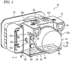
- the brake control device 10 is basically equipped with a base body 12 on which various members, such as solenoid valves described later, are mounted, a motor 14 and a control housing (housing) 16, and these are integrally assembled into a unit.
- the motor 14 is mounted on one side face 12a of the base body 12, the side face 12a extending in the lateral direction of the base body 12 that is formed into a nearly rectangular parallelepiped shape.
- the control housing 16 is mounted on the other side face 12b of the base body 12, the side face 12b being on the opposite side of the one side face 12a.
- An electronic control unit and electrical components are accommodated therein.
- a pair of inlet ports (connection ports) 18 and 18 is formed so as to be open at the left and right upper end portions of the one side face 12a of the base body 12 on which the motor 14 is mounted.
- a pair of outlet ports (connection ports) 20 and 20 is formed so as to be open on the upper face 12c of the base body 12.
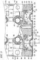
- the base body 12 is formed of a metallic member having a nearly rectangular parallelepiped shape. Fluid passages (not shown) through which brake fluid (a kind of fluid) flows and a motor mounting hole 22 (see FIG. 3 ) in which the motor 14 is installed are formed inside the base body 12. Furthermore, a set of inlet valves (not shown) each formed of a normally open solenoid valve and respectively inserted into a set of inlet valve mounting holes 24 and 24 arranged in parallel and a set of outlet valves (not shown) each formed of a normally closed solenoid valve and respectively inserted into a set of outlet valve mounting holes 26 and 26 arranged in parallel are disposed inside the base body 12 as shown in FIG. 3 . Moreover, inside the base body 12, pumps (not shown) are mounted through a set of pump mounting holes 28 and 28 formed in the left and right side faces 12d and 12e of the base body 12.
- Pipes (not shown) from a fluid pressure source (not shown), such as a master cylinder, are connected to the inlet ports 18 and 18, and the brake fluid is introduced from the fluid pressure source.
- the inlet ports 18 and 18 are provided so as to communicate with the inlet valve mounting holes 24 and 24 via fluid passages (not shown).
- Pipes (not shown) leading to wheel brakes are connected to the outlet ports 20 and 20.
- the outlet ports 20 and 20 are provided so as to communicate with the inlet valve mounting holes 24 and 24 and the outlet valve mounting holes 26 and 26 via fluid passages (not shown).
- a pair of reservoirs 32 and 32 is disposed in parallel on the bottom face 12f of the base body 12.
- These reservoirs 32 and 32 have a function of temporarily storing the brake fluid (i.e., the brake fluid flowing out from the wheel cylinder sides of the wheel brakes) that is released through communication passages communicating with the fluid passages of the base body 12 by opening the output valves (solenoid valves) at the time of the pressure reduction control of the wheel brakes.
- the pair of reservoirs 32 and 32 has the same configuration and is equipped with reservoir holes 30 and 30 each having a bottomed cylinder shape and an open end in the bottom face 12f of the base body 12; pistons 34 and 34 that move slidably along the reservoir holes 30 and 30; and springs (compression coil springs) 36 and 36 for biasing the pistons 34 and 34 toward the outlet valve mounting holes 26 and 26 (upward in FIG. 3 ).
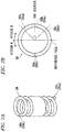
- FIG. 7A is a perspective view of the spring shown in FIG. 3
- FIG. 7B is an enlarged plan view of the spring, showing the phase difference between the beginning end portion and the terminating end portion of the spring.
- the winding beginning end portion 36a and the winding terminating end portion 36b of the spring 36 are disposed at positions opposed to each other in a plan view in the direction of the axis passing through the center of the spring 36.
- the phrase "positions opposed to each other" means that the beginning end portion 36a and the terminating end portion 36b of the spring 36 are disposed at regions (A and B) different from each other while a reference face passing through the axis line of the spring 36 is used as a reference.
- the beginning end portion 36a and the terminating end portion 36b of the spring 36 are set at positions in which the phases of the winding angles thereof are different from each other by approximately 180 degrees. This will be described later in detail.
- the piston 34 is formed into a flat shape such that the sliding length (the length in the axial direction) of the piston 34 is shorter than the maximum radius (R) of the piston 34 (S ⁇ R) as shown in FIG. 3 . This will also be described later in detail.
- the upper end portion of the spring 36 is engaged with a spring seat (seat) 37 formed on the lower face portion 35 of the piston 34.
- the lower end portion of the spring 36 is engaged with each of expanding portions 74 and 74 formed on a plate member 54 described later and protruding toward the deeper sides of the reservoir holes 30 and 30.
- a ring-shaped sealing groove 39 is formed around the outer circumferential face of the piston 34, and a piston packing (sealing member) 38 is installed in the sealing groove 39.
- the sealing groove 39 is formed at an intermediate position in the axial direction of the piston 34 on the sliding face thereof. This will also be described later in detail.
- the reservoir hole 30 is divided by the piston packing 38 into a fluid pressure chamber 40 which is located on the upper side and into which the brake fluid is introduced and a gas chamber 42 in which the spring 36 is disposed.
- C-shaped clips 44, 44 are installed on the inner circumferential faces of the reservoir holes 30, 30. The C-shaped clip 44 makes contact with the outer circumferential face on the lower end side of the piston 34 via a ring-shaped concave portion.
- the fluid pressure chamber 40 is provided so as to communicate with the outlet valve counting hole 26 via a first passage 46 extending in the up-down direction and to communicate with the pump mounting hole 28 via a second passage 48 extending in parallel with the first passage 46.
- a single lid member 52 for hermetically sealing the plurality of reservoir holes 30 and 30 is secured to the bottom face 12f of the base body 12 via a plurality of screw members 50.
- This lid member 52 is equipped with the plate member 54 with which the lower end portions of the springs 36 and 36 make contact; and a ring-shaped sealing member (seal ring) 56 disposed between the bottom face 12f (one face) of the base body 12 to which the plate member 54 is secured and the upper face 54a (the other face) of the plate member 54 opposed to the bottom face 12f (one face) of the base body 12.
- the lid member 52 is secured to the bottom face 12f of the base body 12
- the present invention is not limited to this example.
- the lid member 52 may be secured to, for example, one side face 12a or the other side face 12b of the base body 12.
- the reservoirs 32 and 32 are provided on the one side face 12a or the other side face 12b of the base body 12.
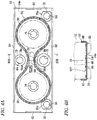
- the ring-shaped sealing member 56 is disposed in a shape similar to that of a pair of glasses along the flat upper face 54a of the plate member 54 and secured to the upper face 54a of the plate member 54 using an adhesive, for example.
- the sealing member 56 is formed of, for example, a metal gasket, a metal gasket coated with rubber on the surface, a paper gasket, an elastic member made of rubber or the like, or a fluid sealant formed of a fluid gasket, such as a silicone-based gasket.
- the sealing member 56 is held between the bottom face 12f of the base body 12 and the upper face 54a of the plate member 54, thereby providing a sealing function.
- a clearance portion 58 is formed between the central portion of the bottom face 12f of the base body 12 and the upper face 54a of the plate member 54. This clearance portion 58 will be described later.
- the plate member 54 is formed into a rectangular flat plate in a plan view.
- This plate member 54 has long-side ribs 60 and 60 formed by upward bending both the side end portions of the long sides thereof extending in the long-side direction and has short-side ribs 62 and 62 formed by upward bending both the end portions of the short sides thereof extending in the short-side direction perpendicular to the long-side direction, the both the end portions of the short sides being provided in the axial direction of the plate member 54.
- both the long sides and both the short sides of the rectangular plate member 54 are bent so that the pair of long-side ribs 60 and 60 is opposed to each other and so that the pair of short-side ribs 62 and 62 is opposed to each other.
- the plate member 54 is preferably formed of, for example, a thin metal plate or a resin material.
- the long-side ribs 60 and 60 are formed so as to partly cover the lower sides of both the side faces 12a and 12b extending from the bottom face 12f (one face) of the base body 12 as shown in FIG. 5 .
- the short-side ribs 62 and 62 are provided so as to make contact with the bottom face 12f of the base body 12.
- the plate member 54 has a plurality of screw holes 64 for allowing the screw members 50 to be inserted is formed at three positions: two corner positions where one of the long-side ribs 60 and 60 intersects the short-side ribs 62 and 62, and one position at the central region of one of the long sides.
- the plurality of screw holes 64 are disposed outside the region surrounded by the ring-shaped sealing member 56.
- a communication passage 66 communicating with the plurality of reservoir holes 30 and 30 is provided inside the region surrounded by the ring-shaped sealing member 56.
- the communication passage 66 is formed of the clearance portion 58 (see FIG. 3 ) formed by a distance space between the central flat face of the bottom face 12f of the base body 12 and the flat upper face 54a of the plate member 54 in the up-down direction (vertical direction); and a distance portion 68 (see FIG. 4 ) that is a region surrounded by the ring-shaped sealing member 56 in the horizontal direction and formed such that circular portions 56a and 56a constituting parts of the sealing member 56 are separated from each other by a certain distance in the lateral direction (horizontal direction).
- a disc-shaped frame portion 70 surrounding the screw hole 64 is provided around the screw hole 64.
- the frame portion 70 is formed as described below: a protruding portion (refer to the portion indicated by broken lines) protruding in a nearly cylindrical shape is formed by performing burring processing with, for example, a punch (not shown), and the protruding portion is folded back toward the radially outward direction using another punch (not shown) so as to be made close contact with the upper face 54a of the plate member 54.
- the upper face of the frame portion 70 is formed of a flat face and functions as a seat face 70a making contact with the bottom face 12f of the base body 12 when the plate member 54 is secured to the bottom face 12f of the base body 12.
- the height dimension (upward protruding dimension) of the seat face 70a of the frame portion 70 is set so as to be equal or nearly equal to the height dimension of the short-side rib 62.
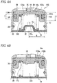
- the height dimension t1 (upward protruding dimension) of the seat face 70a of the frame portion 70 is set so as to be smaller than the height dimension t2 of the sealing face of the sealing member 56 when the sealing member 56 is in its non-compressed state (t1 ⁇ t2) as shown in FIG. 6A .
- the seat face 70a of the frame portion 70 makes contact with the bottom face 12f (one face) of the base body 12, whereby the screwing amount of the screw member 50 is limited and the compression amount of the sealing member 56 is restricted.
- a circular through hole 72 passing through the upper and lower faces of the plate member 54 is formed in the plate member 54.
- This through hole 72 functions as a communication passage leading to a vehicle mounting screw hole (not shown) provided in the bottom face 12f of the base body 12.
- the height dimension of the frame portion surrounding the through hole 72 is also set so as to be nearly equal to that of the frame portion 70 of the screw hole 64, whereby the compression amount of the sealing member 56 is securely restricted by the frame portion of the through hole 72 together with the seat faces 70a.
- the expanding portions 74 and 74 engaged with the lower end portions of the springs 36 and 36 so as to function as spring guides are provided on the flat upper face (flat face portion) 54a of the plate member 54. These expanding portions 74 and 74 do not protrude toward the lower face of the plate member 54 but protrude toward the deeper sides of the reservoir holes 30 and 30.
- the plate member 54 Since the expanding portions 74 and 74 protruding toward the deeper sides of the reservoir holes 30 and 30 are provided on the flat upper face (flat face portion) 54a of the plate member 54 as described above, the plate member 54 does not protrude from the bottom face 12f of the base body 12, and spring guides formed of the expanding portions 74 and 74 can be provided on the plate member 54. As a result, the base body 12 can be made smaller in size while the springs 36 and 36 are operated properly.
- the base body 12 is provided with a respiratory hole 76, the open end of which faces the inside of the sealing member 56 and communicates with the communication passage 66 and through which air passing through the communication passage 66 flows in and out.
- This respiratory hole 76 is provided so as to be open near the central portion of the bottom face 12f of the base body 12, to extend upward from its open end and to communicate with a vent hole 78 passing through the base body 12 in the lateral direction.
- This vent hole 78 communicates with at least one of the control housing 16 and the motor 14 (both of the control housing 16 and the motor 14 in this embodiment).
- the plate member 54 is screwed to the bottom face 12f of the base body 12 via the plurality of screw members 50, it may be possible, for example, that the edge portions of the plate member 54 are swaged so as to be secured to the base body 12 or that the plate member 54 is press-fitted into a groove portion (not shown) formed in the bottom face 12f of the base body 12.
- the sealing member 56 is positioned on the upper face 54a of plate member 54 and bonded thereto, it may be possible, for example, that the sealing member 56 is provided so as to be held and engaged between the bottom face 12f of the base body 12 and the upper face 54a of the plate member 54 or that engaging portions (not shown) are provided on the upper face 54 of the plate member 54 and engaged with the sealing member 56.
- Vent passages communicating with the outside are formed in the control housing 16, and the vent passages are each provided with a moisture permeable waterproof element (breathable waterproof member) (not shown) that prevents the transport of moisture while allowing the transport of air. It is preferable, for example, that a known product under the trade name of GORE-TEX (registered trademark) be used as this moisture permeable waterproof element.
- GORE-TEX registered trademark
- the moisture permeable waterproof element when provided, can prevent the entry of moisture, dust, etc. into the internal space of the control housing 16.
- the vent hole 78 formed so as pass through the base body 12 communicates with the inside of the motor 14 and the inside of the control housing 16, and the inside of the control housing 16 communicates with the outside via the breathable waterproof member.
- the pressure inside the gas chamber 42 can be maintained at atmospheric pressure while the insides of the reservoirs 32 and 32 are sealed hermetically and securely with the sealing member 56.
- the brake control device 10 is basically configured as described above, and the operation and working effects of the device will be described below.
- the brake fluid tends to flow into the fluid pressure chamber 40 of the reservoir 32 via the first passage 46 that communicates with the outlet valve mounting hole 26 in which the output valve is mounted.
- the piston 34 is pressed by the brake fluid introduced into the fluid pressure chamber 40, and the piston 34 is pressed against the spring force of the spring 36 and is moved toward the plate member 54.
- the brake fluid is allowed to flow into the fluid pressure chamber 40, and the volume of the brake fluid corresponding to the movement distance of the piston 34 along the reservoir hole 30 is stored.
- the capacity of the gas chamber 42 is reduced when the piston 34 is moved, since the communication passage 66 communicates with the control housing 16, etc. communicating with the atmosphere via the respiratory hole 76 and the vent hole 78, the internal pressure therein does not rise.
- the motor 14 is driven and rotated using a drive signal output from the electronic control unit (not shown) accommodated inside the control housing 16.
- the pump (not shown) mounted in the pump mounting hole 28 operates, and the brake fluid stored inside the fluid pressure chamber 40 of the reservoir 32 passes through the second passage 48 and flows out, thereby being returned to a fluid passage (not shown) inside the base body 12.
- the piston 34 is pressed in a direction of moving away from the plate member 54 by virtue of the spring force of the spring 36, and the capacity of the fluid pressure chamber 40 is reduced, whereby the piston 34 is returned to its initial state.
- the pair of reservoirs 32 and 32 will be described below in detail. Since the reservoirs 32 and 32 have the same configuration, one of the reservoirs 32 and 32 will be described, and the descriptions of the other reservoir 32 are omitted.
- FIG. 7A is a perspective view showing the compression coil spring shown in FIG. 3
- FIG. 7B is an enlarged plan view of the compression coil spring, showing the phase difference between the beginning end portion and the terminating end portion thereof.
- the winding beginning end portion 36a and the winding terminating end portion 36b of the spring 36 are set at positions opposed to each other in the radial direction (positions in which the phases of the winding angles thereof are different by approximately 180 degrees).
- the phase difference in winding angle be set, for example, in the range of 180 ⁇ 45 degrees (the phase difference is in the range of 135 to 225 degrees) (see the range indicated by the dashed lines of FIG. 7B ).
- the phases of the winding angles of the winding beginning end portion 36a and the winding terminating end portion 36b are set so as to be different from each other by approximately 180 degrees, when the spring 36 is deflected, the spring load generated at the beginning end portion 36a is made equal to that generated at the terminating end portion 36b. As a result, any unbalanced spring load applied to the piston 34 can be suppressed, whereby it is possible to ensure stable sliding performance of the piston 34. It is preferable that the number of effective turns of the spring 36 be set so as to be increased from 0. 5 turns in increments of 1 turn (0.5 turns, 1.5 turns, 2.5 turns, 3.5 turns, ).
- the spring seat 37 for receiving the spring 36 is provided on the lower face portion 35 of the piston 34 that is opposed to the expanding portion 74.
- the spring 36 can be restricted from moving in a direction nearly perpendicular to the axial direction (the play of the spring in the left-right direction in FIG. 3 can be restricted) by virtue of the spring seat 37 of the piston 34 and the expanding portion 74 of the plate member 54. As a result, the positional displacement of the spring 36 can be avoided, and the spring 36 can deliver a stable spring force.
- the piston 34 sliding along the reservoir hole 30 is formed into a flat shape in which the sliding length (the length in the axial direction) (S) of the piston 34 is set so as to be smaller than the maximum radius (R) of the piston 34 (S ⁇ R).
- the sliding length (S) of the piston 34 is set so as to be smaller than the maximum radius (R) of the piston 34 (S ⁇ R)
- the length of the reservoir hole 30 in the axial direction can be shortened, and the base body 12 can be made compact in size.
- the reservoir 32 can be made compact in size by virtue of the synergistic effect of the flat shape of the piston 34 and the fact that the spring load at the beginning end portion 36a of the spring 36 is made equal to that at the terminating end portion 36b thereof owing to the phase difference between the beginning end portion 36a and the terminating end portion 36b.
- the sealing groove 39 for accommodating the piston packing 38 is formed in the piston 34. More specifically, the sealing groove 39 is formed at the intermediate position in the axial direction of the piston 34 on its sliding face making sliding contact with the reservoir hole 30. In other words, the sealing groove 39 is disposed in the central portion of the sliding face of the piston 34 wherein the central portion does not make contact with the end portions of the sliding face.
- the sealing groove 39 is formed at the intermediate position in the axial direction of the piston 34 on its sliding face, the piston 34 can be slid stably along the reservoir hole 30. Even if the piston 34 is made compact in size, tilting and twisting of the piston 34 can be minimized.
- the spring seat 37 formed on the lower face portion 35 of the piston 34 is provided at a position in the range (T) of the sealing groove 39 formed in the piston 34 in the axial direction of the piston 34.
- the spring seat 37 is provided at a position in the range (T) of the sealing groove 39 in the axial direction of the piston 34, the spring 36 can be operated at a position close to the position wherein the sliding piston packing 38 (sealing member) is provided. As a result, twisting of the piston 34 can be minimised, and a stable spring force can be applied to the piston 34.
- the sealing groove 39 is formed at the intermediate position in the axial direction on the sliding face of the piston 34 and the spring seat 37 formed on the lower face portion 35 of the piston 34 is provided at the position in the range (T) of the sealing groove 39 formed in the piston 34, the ratio (S/D) of the sliding length (S) of the piston 34 to the maximum diameter (D) of the piston 34 can be set to, for example, 0.4 or less (S/D ⁇ 0.4).
- the lid member 52 is formed of the plate member 54 and the sealing member 56.
- the plurality of screw holes 64 for securing the plate member 54 to the base body 12 are disposed outside the region surrounded by the sealing member 56.
- the communication passage 66 communicating with the plurality of reservoir holes 30 and 30 is provided inside the region surrounded by the sealing member 56.
- the lid member 52 does not protrude more than necessary from the base body 12, and this contributes to the miniaturization of the device.
- the sentence "the lid member 52 does not protrude more than necessary from the base body 12" means that the lid member 52 protrudes from the base body 12 by the thickness of the plate member 54 and the height dimension of the short-side ribs 62 and 62.
- the plate member 54 can have a certain strength in the long-side direction thereof. Furthermore, since the long sides of the sealing member 56 are covered with the long-side ribs 60 and 60 that are formed by simply bending the long sides of the rectangular shape of the plate member 54, the sealing member 56 disposed between the base body 12 and the plate member 54 can be protected effectively.
- the base body 12 can be made waterproof in the short-side direction by simply bending the short sides of the rectangular shape of the plate member 54. Moreover, since the short-side ribs 62 and 62 are made contact with the bottom face 12f of the base body 12, the sealing member 56 can be prevented from being deformed excessively by compression. Besides, the strength of the plate member 54 in the short-side direction can be increased by the short-side ribs 62 and 62.
- the seat faces 70a of the frame portions 70 surrounding the screw holes 64 make contact with the bottom face 12f of the base body 12, whereby the compression amount of the sealing member 56 can be restricted.
- the frame portions 70 formed by simple processing can effectively prevent the sealing member 56 from being compressed excessively.
- the durability of the sealing member 56 can be improved, and the pressure on the sealing face of the ring-shaped sealing member 56 can be maintained uniformly.
- the base body 12 is provided with the respiratory hole 76, the open end of which faces the inside of the sealing member 56 and communicates with the communication passage 66 and through which compressed air passing through the communication passage 66 flows in and out, the compressed air generated when the pistons 34 and 34 slide along the reservoir holes 30 and 30 can be preferably discharged to the outside via the communication passage 66 and the respiratory hole 76.
- the brake control device 10 preferably used for motorcycles is taken as an example, the above-mentioned technical features can also be applied to brake control devices for four-wheel automobiles.
- FIG. 8A is an enlarged vertical sectional view showing the reservoir of the brake fluid pressure control device for a vehicle according to the other embodiment of the present invention
- FIG. 8B is an enlarged vertical sectional view showing a reservoir according to a modified example.
- this embodiment is different from the above-mentioned embodiment in that an inner coil spring 102a and an outer coil spring 102b are used as the springs of the device,
- the inner coil spring 102a and the outer coil spring 102b are disposed coaxially and doubly on the inner circumferential side and the outer circumferential side thereof inside the reservoir hole 30 of the reservoir 32a.
- the spring load of the outer coil spring 102b is set so as to be larger than that of the inner coil spring 102a.
- the required deflection amounts of the inner coil spring 102a and the outer coil spring 102b in the axial direction can be made smaller than that of a single coil spring.
- the reservoir 32a can be made more compact in size, and the inner coil spring 102a and the outer coil spring 102b can be operated properly for the piston 34a.
- the phases of the winding angles of the beginning end portion and the terminating end portion of each of the inner coil spring 102a and the outer coil spring 102b may be set so as to be similar to those of the spring 36 shown in FIGS. 7A and 7B .
- an inner seat 104a for receiving the inner coil spring 102a and an outer seat 104b for receiving the outer coil spring 102b are provided on the lower face portion 35 of the piston 34a that is opposed to the expanding portion 74.
- a ring-shaped step portion 106 is provided between the inner seat 104a and the outer seat 104b.
- the inner coil spring 102a can be restricted from moving in a direction nearly perpendicular to the axial direction (the looseness of the spring in the left-right direction in FIG. 8A can be restricted) by virtue of the step portion 106 formed between the inner seat 104a and the outer seat 104b.
- the inner coil spring 102a and the outer coil spring 102b can deliver stable spring forces while the coil springs are prevented from making contact with each other.
- FIG. 8B shows a modified example, i.e., a reservoir 32b that is not provided with the step portion 106.
- the components corresponding to those shown in FIG. 8A are designated by the same reference characters and described below.
- both the inner coil spring 102a and the outer coil spring 102b are supported using a ring-shaped concave portion 110 instead of the step portion 106.
- the reservoir 32a is advantageous in that the cutting work for the lower face portion 35 of the piston 34a can be carried out easily and the cost of manufacturing can be lowered in comparison with the reservoir 32b.
- the piston 34a sliding along the reservoir hole 30 is formed into a flat shape in which the sliding length (the length in the axial direction) (S) of the piston 34a is set so as to be smaller than the maximum radius (R) of the piston 34a (S ⁇ R).
- the sliding length (S) of the piston 34a is set so as to be smaller than the maximum radius (R) of the piston 34a (S ⁇ R)
- the length of the reservoir hole 30 in the axial direction can be shortened, and the base body 12 can be made compact in size.
- the reservoir 32a can be made compact in size by virtue of the synergistic effect of the flat shape of the piston 34a and the fact that the spring load at the beginning end portion 103a of each of the inner coil spring 102a and the outer coil spring 102b is made equal to that at the terminating end portion 103b thereof owing to the phase difference between the beginning end portion 103a and the terminating end portion 103b.
- a sealing groove 108 for accommodating the piston packing 38 is formed in the piston 34a. More specifically, the sealing groove 108 is formed at the intermediate position in the axial direction of the piston 34a on its sliding face making sliding contact with the reservoir hole 30. In other words, the sealing groove 108 is disposed in the central portion of the sliding face of the piston 34a wherein the central portion does not make contact with the end portions of the sliding face.
- the sealing groove 108 is formed at the intermediate position in the axial direction of the piston 34a on its sliding face, the piston 34a can be slid stably along the reservoir hole 30. Even if the piston 34a is made compact in size, tilting and twisting of the piston 34a can be minimized.
- the inner seat 104a and the outer seat 104b formed on the lower face portion 35 of the piston 34a are provided at positions in the range (T) of the sealing groove 108 formed in the piston 34a in the axial direction of the piston 34a.
- the inner seat 104a and the outer seat 104b are provided at positions in the range (T) of the sealing groove 108 in the axial direction of the piston 34a, the inner coil spring 102a and the outer coil spring 102b can be operated at positions close to the position wherein the sliding piston packing 38 (sealing member) is provided. As a result, twisting of the piston 34s can be minimized, and stable spring forces can be applied to the piston 34a.
Landscapes
- Physics & Mathematics (AREA)
- Electromagnetism (AREA)
- Engineering & Computer Science (AREA)
- Fluid Mechanics (AREA)
- Transportation (AREA)
- Mechanical Engineering (AREA)
- Regulating Braking Force (AREA)
- Transmission Of Braking Force In Braking Systems (AREA)
Claims (12)
- Dispositif de commande de pression de liquide de freins (10) pour un véhicule, le dispositif comprenant :un corps de base (12) ;une pluralité de réservoirs (32) configurés pour stocker le liquide de freins et prévus dans le corps de base (12), dans lequel les réservoirs sont disposés en parallèle ; etun élément formant couvercle unique (52) fixé au corps de base (12),dans lequel chacun des réservoirs (32) a un trou de réservoir (30), un piston (34) qui coulisse à l'intérieur du trou de réservoir (30) et un ressort (36) qui sollicite le piston (34),dans lequel l'élément formant couvercle (52) scelle hermétiquement la pluralité de trous de réservoir (30),dans lequel l'élément formant couvercle (52) comprend un élément formant plaque (54) avec lequel les ressorts (36) établissent un contact, etdans lequel l'élément formant couvercle (52) comprend en outre un élément d'étanchéité annulaire (56) maintenu entre une face particulière (12f) du corps de base (12) à laquelle l'élément formant plaque (54) est fixé et une face particulière (54a) de l'élément formant plaque (54) opposée à la face particulière (12f) du corps de base (12) afin de prévoir une fonction d'étanchéité, et ce, dans l'élément formant couvercle (52),un trou de vis (64) formé dans l'élément formant plaque (54) et configuré pour fixer l'élément formant plaque (54) au corps de base (12) est disposé à l'extérieur d'une région entourée par l'élément d'étanchéité (56), etun passage de communication (66) communiquant avec la pluralité de trous de réservoir (30) est prévu à l'intérieur de la région entourée par l'élément d'étanchéité (56),caractérisé en ce quel'élément formant plaque (54) est formé en une forme rectangulaire dans une vue en plan et a une nervure côté long (60) formée en pliant au moins l'un des côtés longs de la forme rectangulaire, etlorsque l'élément formant plaque (54) est fixé au corps de base (12), la nervure côté long (60) est formée afin de couvrir au moins une partie d'une face latérale du corps de base (12) s'étendant à partir de la face particulière (12f) du corps de base (12).
- Dispositif de commande de pression de liquide de freins (10) pour un véhicule selon la revendication 1,
dans lequel l'élément formant plaque (54) a une nervure côté court (62) formée en pliant au moins un des côtés courts de la forme rectangulaire, et
dans lequel, quand l'élément formant plaque (54) est fixé au corps de base (12), la nervure côté court (62) est prévue afin d'établir un contact avec la face particulière du corps de base (12). - Dispositif de commande de pression de liquide de freins (10) pour un véhicule selon l'une quelconque des revendications 1 et 2,
dans lequel le trou de vis (64) formé dans l'élément formant plaque (54) a une portion châssis (70) qui est formée en rabattant une portion saillante formée par un traitement d'ébavurage vers la direction extérieure de façon radiale afin d'entourer le trou de vis (64), et
dans lequel, lorsque l'élément formant plaque (54) est fixé au corps de base (12), la portion châssis (70) établit un contact avec la face particulière (12f) du corps de base (12), limitant de ce fait la quantité de compression de l'élément d'étanchéité (56). - Dispositif de commande de pression de liquide de freins (10) pour un véhicule selon l'une quelconque des revendications 1 à 3,
dans lequel le corps de base (12) est muni d'un trou de respiration (76), l'extrémité ouverte du trou de respiration (76) fait face à l'intérieur de l'élément d'étanchéité (56) et communique avec le passage de communication (66), et un gaz passant à travers le passage de communication (66) s'écoule dans les deux sens à travers le trou de respiration (76). - Dispositif de commande de pression de liquide de freins (10) pour un véhicule selon la revendication 4, le dispositif (10) comprenant en outre :un moteur (14) monté sur le corps de base (12) pour entraîner des pompes incorporées dans le corps de base (12), etun logement (16) monté sur le corps de base (12) pour loger des composants électriques,dans lequel le trou de respiration (76) et un trou d'évent (78) communiquant avec au moins un de l'intérieur du moteur (14) et l'intérieur du logement (16) sont formés dans le corps de base (12) afin de passer à travers, etl'intérieur du logement (16) est formé afin de communiquer avec l'extérieur via un élément imperméable respirable.
- Dispositif de commande de pression de liquide de freins (10) pour un véhicule selon l'une quelconque des revendications 1 à 5,
dans lequel l'élément formant plaque (54) est formé d'une plaque plate, et la face particulière (54a) de l'élément formant plaque (54) opposée à la face particulière (12f) du corps de base (12) est une portion de face plate,
dans lequel des portions en extension (74) s'étendant vers des côtés plus profonds des réservoirs (32) sont formées sur la portion de face plate,
dans lequel les portions en extension (74) servent de guides pour les ressorts (36). - Dispositif de commande de pression de liquide de freins (10) pour un véhicule selon l'une quelconque des revendications 1 à 6,
dans lequel le piston (34) est formé en une forme plate dans laquelle une longueur de coulissement du piston (34) est réglée pour être plus petite que le rayon du piston (34). - Dispositif de commande de pression de liquide de freins (10) pour un véhicule selon la revendication 7,
dans lequel une rainure d'étanchéité (39) est formée dans le piston (34), et
la rainure d'étanchéité (39) est formée au niveau d'une position intermédiaire dans la direction axiale du piston (34) sur une face de coulissement du piston (34). - Dispositif de commande de pression de liquide de freins (10) pour un véhicule selon l'une quelconque des revendications 1 à 8,
dans lequel la portion d'extrémité de commencement d'enroulement (36a) et la portion d'extrémité de fin d'enroulement (36b) du ressort (36) sont mises à des positions opposées l'une à l'autre dans une vue en plan par rapport à la direction axiale du ressort (36). - Dispositif de commande de pression de liquide de freins (10) pour un véhicule selon la revendication 8 et 9,
dans lequel un siège (37) qui reçoit le ressort (36) est prévu au niveau d'une position dans les limites d'une plage de la rainure d'étanchéité (39) formée dans le piston (34) dans la direction axiale du piston (34). - Dispositif de commande de pression de liquide de freins (10) pour un véhicule selon l'une quelconque des revendications 1 à 10,
dans lequel le ressort (36) comprend un ressort hélicoïdal intérieur (102a) et un ressort hélicoïdal extérieur (102b), et le ressort hélicoïdal intérieur (102a) et le ressort hélicoïdal extérieur (102b) sont disposés de façon coaxiale et doublement sur le côté circonférentiel intérieur et le côté circonférentiel extérieur de celui-ci. - Dispositif de commande de pression de liquide de freins (10) pour un véhicule selon la revendication 11,
dans lequel un siège intérieur (104a) qui reçoit le ressort hélicoïdal intérieur (102a) et un siège extérieur (104b) qui reçoit le ressort hélicoïdal extérieur (102b) sont prévus pour le réservoir,
dans lequel une portion à épaulement (106) est prévue entre le siège intérieur (104a) et le siège extérieur (104b).
Applications Claiming Priority (3)
| Application Number | Priority Date | Filing Date | Title |
|---|---|---|---|
| JP2010084107 | 2010-03-31 | ||
| JP2011037742A JP5209748B2 (ja) | 2010-03-31 | 2011-02-24 | 車両用ブレーキ液圧制御装置 |
| JP2011037743A JP5351914B2 (ja) | 2011-02-24 | 2011-02-24 | 車両用ブレーキ液圧制御装置 |
Publications (3)
| Publication Number | Publication Date |
|---|---|
| EP2371638A2 EP2371638A2 (fr) | 2011-10-05 |
| EP2371638A3 EP2371638A3 (fr) | 2013-03-06 |
| EP2371638B1 true EP2371638B1 (fr) | 2018-08-15 |
Family
ID=43978019
Family Applications (1)
| Application Number | Title | Priority Date | Filing Date |
|---|---|---|---|
| EP11160598.6A Not-in-force EP2371638B1 (fr) | 2010-03-31 | 2011-03-31 | Dispositif de commande de pression de liquide de frein pour véhicule |
Country Status (2)
| Country | Link |
|---|---|
| US (1) | US9073526B2 (fr) |
| EP (1) | EP2371638B1 (fr) |
Families Citing this family (5)
| Publication number | Priority date | Publication date | Assignee | Title |
|---|---|---|---|---|
| JP6237484B2 (ja) * | 2014-06-12 | 2017-11-29 | 株式会社アドヴィックス | 車両用ブレーキ装置の液圧ユニット |
| USD867239S1 (en) * | 2017-01-31 | 2019-11-19 | Nissin Kogyo Co., Ltd. | Brake control unit |
| KR102006497B1 (ko) * | 2017-05-11 | 2019-10-08 | 주식회사 만도 | 전자식 브레이크 시스템용 밸브블록 |
| US12129922B2 (en) | 2020-11-19 | 2024-10-29 | Sonnax Transmission Company | Drop-in signal accumulator piston kit and method for replacing an original equipment signal accumulator piston |
| US11933326B2 (en) | 2020-11-19 | 2024-03-19 | Sonnax Transmission Company | Drop-in signal accumulator piston kit and method for replacing an original equipment signal accumulator piston |
Family Cites Families (19)
| Publication number | Priority date | Publication date | Assignee | Title |
|---|---|---|---|---|
| US3058374A (en) | 1957-05-21 | 1962-10-16 | Self Changing Gears Ltd | Fluid pressure control or servo systems |
| US3595449A (en) * | 1969-10-13 | 1971-07-27 | Clevepak Corp | Dispensing container with follower discharge assistant |
| US4799048A (en) * | 1984-09-28 | 1989-01-17 | Nippondenso Co., Ltd. | Accumulator |
| DE4306222A1 (de) | 1992-10-09 | 1994-09-01 | Teves Gmbh Alfred | Hydraulikaggregat für schlupfgeregelte Bremsanlagen |
| DE4438163A1 (de) | 1994-10-26 | 1996-05-02 | Teves Gmbh Alfred | Hydraulikaggregat |
| JP3936427B2 (ja) | 1997-04-08 | 2007-06-27 | Nskワーナー株式会社 | 圧縮コイルばね |
| DE19724166A1 (de) * | 1997-06-07 | 1998-12-10 | Bosch Gmbh Robert | Hydraulisches Aggregat für eine Fahrzeugbremsanlage |
| JP3463857B2 (ja) | 1998-05-22 | 2003-11-05 | 株式会社ボッシュオートモーティブシステム | ブレーキ液圧制御装置 |
| US6354674B1 (en) * | 1998-12-11 | 2002-03-12 | Denso Corporation | Hydraulic control apparatus integrated with motor driving circuit unit |
| US6390133B1 (en) | 2000-05-17 | 2002-05-21 | Robert Bosch Corporation | Hydraulic accumulator vent and method for making the same |
| JP4680509B2 (ja) | 2002-02-08 | 2011-05-11 | コンチネンタル・テベス・アーゲー・ウント・コンパニー・オーハーゲー | スリップ制御ブレーキシステムのための液圧ユニット |
| US6899211B2 (en) * | 2002-02-26 | 2005-05-31 | Sonnax Industries, Inc. | Pinless accumulator piston |
| JP2004338565A (ja) | 2003-05-15 | 2004-12-02 | Continental Teves Ag & Co Ohg | 車両用ブレーキ液圧制御アクチュエータ |
| JP4870015B2 (ja) | 2006-06-13 | 2012-02-08 | 京三電機株式会社 | 圧力調整弁 |
| JP2009068644A (ja) * | 2007-09-14 | 2009-04-02 | Denso Corp | スプリング装置およびアクセルペダル装置 |
| JP5003386B2 (ja) | 2007-09-28 | 2012-08-15 | アイシン・エィ・ダブリュ株式会社 | コイルスプリング |
| DE102007060951A1 (de) | 2007-12-18 | 2009-06-25 | Robert Bosch Gmbh | Druckspeicher, insbesondere für ein Hydroaggregat einer hydraulischen Fahrzeugbremsanlage mit elektronischer Radschlupfregelung |
| US20090212476A1 (en) * | 2008-02-21 | 2009-08-27 | Renton Coil Spring Co. | Compression springs and methods of making same |
| JP5302997B2 (ja) * | 2011-03-25 | 2013-10-02 | 日信工業株式会社 | 車両用ブレーキ液圧制御装置 |
-
2011
- 2011-03-30 US US13/075,686 patent/US9073526B2/en active Active
- 2011-03-31 EP EP11160598.6A patent/EP2371638B1/fr not_active Not-in-force
Non-Patent Citations (1)
| Title |
|---|
| None * |
Also Published As
| Publication number | Publication date |
|---|---|
| US20110239641A1 (en) | 2011-10-06 |
| EP2371638A2 (fr) | 2011-10-05 |
| EP2371638A3 (fr) | 2013-03-06 |
| US9073526B2 (en) | 2015-07-07 |
Similar Documents
| Publication | Publication Date | Title |
|---|---|---|
| EP2371638B1 (fr) | Dispositif de commande de pression de liquide de frein pour véhicule | |
| EP2502795B1 (fr) | Appareil de contrôle de pression hydraulique pour frein de véhicule | |
| US9086161B2 (en) | Valve apparatus with positive and negative pressure relief valves | |
| JP2004338565A (ja) | 車両用ブレーキ液圧制御アクチュエータ | |
| US9663084B2 (en) | Rotating pumping apparatus with seal mechanism | |
| JP4602434B2 (ja) | 車両用ブレーキ液圧制御装置のリザーバ | |
| EP2323881B1 (fr) | Unité de commande hydraulique à deux canaux linéaires | |
| JP5005516B2 (ja) | 油路制御用モジュレータ | |
| JP5438853B2 (ja) | 車両用ブレーキ液圧制御装置 | |
| CN102312809A (zh) | 用于流体泵的脉动缓冲元件及相应的流体泵 | |
| JP5351914B2 (ja) | 車両用ブレーキ液圧制御装置 | |
| JP5498231B2 (ja) | 車両用ブレーキ液圧制御装置 | |
| JP6395940B2 (ja) | 成形シールに基づいて可変の流動接続を有する圧縮媒体装置 | |
| JPH11139285A (ja) | 車両用ブレーキ装置における液圧ユニットのリザーバ | |
| JP2006513905A (ja) | 圧力コントローラ | |
| JP4989536B2 (ja) | 車両用ブレーキ液圧制御装置 | |
| JP5086866B2 (ja) | 車両用ブレーキ液圧制御装置のリザーバ | |
| JP5022397B2 (ja) | 車両用ブレーキ液圧制御装置 | |
| JP5432945B2 (ja) | 車両用ブレーキ液圧制御装置 | |
| JP2001001885A5 (fr) | ||
| JP4929137B2 (ja) | 車両のブレーキ油圧制御装置 | |
| JP5558175B2 (ja) | 車両ブレーキ装置 | |
| JPH1035479A (ja) | 車両ブレーキシステムのための液圧式のリザーバ | |
| JP2008115963A (ja) | 機器収納室のシール装置およびそれを使用したブレーキ液圧制御装置 | |
| JP2007113764A (ja) | ダイヤフラム式制御弁 |
Legal Events
| Date | Code | Title | Description |
|---|---|---|---|
| PUAI | Public reference made under article 153(3) epc to a published international application that has entered the european phase |
Free format text: ORIGINAL CODE: 0009012 |
|
| AK | Designated contracting states |
Kind code of ref document: A2 Designated state(s): AL AT BE BG CH CY CZ DE DK EE ES FI FR GB GR HR HU IE IS IT LI LT LU LV MC MK MT NL NO PL PT RO RS SE SI SK SM TR |
|
| AX | Request for extension of the european patent |
Extension state: BA ME |
|
| RIN1 | Information on inventor provided before grant (corrected) |
Inventor name: NAKAMURA, MOTOYASU Inventor name: KODAMA, TAKURO |
|
| PUAL | Search report despatched |
Free format text: ORIGINAL CODE: 0009013 |
|
| AK | Designated contracting states |
Kind code of ref document: A3 Designated state(s): AL AT BE BG CH CY CZ DE DK EE ES FI FR GB GR HR HU IE IS IT LI LT LU LV MC MK MT NL NO PL PT RO RS SE SI SK SM TR |
|
| AX | Request for extension of the european patent |
Extension state: BA ME |
|
| RIC1 | Information provided on ipc code assigned before grant |
Ipc: F16F 1/04 20060101ALN20130125BHEP Ipc: B60T 8/36 20060101AFI20130125BHEP |
|
| 17P | Request for examination filed |
Effective date: 20130820 |
|
| RBV | Designated contracting states (corrected) |
Designated state(s): AL AT BE BG CH CY CZ DE DK EE ES FI FR GB GR HR HU IE IS IT LI LT LU LV MC MK MT NL NO PL PT RO RS SE SI SK SM TR |
|
| STAA | Information on the status of an ep patent application or granted ep patent |
Free format text: STATUS: EXAMINATION IS IN PROGRESS |
|
| 17Q | First examination report despatched |
Effective date: 20171103 |
|
| GRAP | Despatch of communication of intention to grant a patent |
Free format text: ORIGINAL CODE: EPIDOSNIGR1 |
|
| STAA | Information on the status of an ep patent application or granted ep patent |
Free format text: STATUS: GRANT OF PATENT IS INTENDED |
|
| RIC1 | Information provided on ipc code assigned before grant |
Ipc: F16F 1/04 20060101ALN20180410BHEP Ipc: B60T 8/36 20060101AFI20180410BHEP |
|
| INTG | Intention to grant announced |
Effective date: 20180502 |
|
| GRAS | Grant fee paid |
Free format text: ORIGINAL CODE: EPIDOSNIGR3 |
|
| GRAA | (expected) grant |
Free format text: ORIGINAL CODE: 0009210 |
|
| STAA | Information on the status of an ep patent application or granted ep patent |
Free format text: STATUS: THE PATENT HAS BEEN GRANTED |
|
| RAP1 | Party data changed (applicant data changed or rights of an application transferred) |
Owner name: NISSIN KOGYO CO., LTD. |
|
| AK | Designated contracting states |
Kind code of ref document: B1 Designated state(s): AL AT BE BG CH CY CZ DE DK EE ES FI FR GB GR HR HU IE IS IT LI LT LU LV MC MK MT NL NO PL PT RO RS SE SI SK SM TR |
|
| REG | Reference to a national code |
Ref country code: CH Ref legal event code: EP Ref country code: GB Ref legal event code: FG4D Ref country code: AT Ref legal event code: REF Ref document number: 1029382 Country of ref document: AT Kind code of ref document: T Effective date: 20180815 |
|
| RIN1 | Information on inventor provided before grant (corrected) |
Inventor name: NAKAMURA, MOTOYASU Inventor name: KODAMA, TAKURO |
|
| REG | Reference to a national code |
Ref country code: IE Ref legal event code: FG4D |
|
| REG | Reference to a national code |
Ref country code: DE Ref legal event code: R096 Ref document number: 602011050993 Country of ref document: DE |
|
| REG | Reference to a national code |
Ref country code: ES Ref legal event code: FG2A Ref document number: 2685074 Country of ref document: ES Kind code of ref document: T3 Effective date: 20181005 |
|
| REG | Reference to a national code |
Ref country code: NL Ref legal event code: MP Effective date: 20180815 |
|
| REG | Reference to a national code |
Ref country code: LT Ref legal event code: MG4D |
|
| REG | Reference to a national code |
Ref country code: AT Ref legal event code: MK05 Ref document number: 1029382 Country of ref document: AT Kind code of ref document: T Effective date: 20180815 |
|
| PG25 | Lapsed in a contracting state [announced via postgrant information from national office to epo] |
Ref country code: RS Free format text: LAPSE BECAUSE OF FAILURE TO SUBMIT A TRANSLATION OF THE DESCRIPTION OR TO PAY THE FEE WITHIN THE PRESCRIBED TIME-LIMIT Effective date: 20180815 Ref country code: IS Free format text: LAPSE BECAUSE OF FAILURE TO SUBMIT A TRANSLATION OF THE DESCRIPTION OR TO PAY THE FEE WITHIN THE PRESCRIBED TIME-LIMIT Effective date: 20181215 Ref country code: AT Free format text: LAPSE BECAUSE OF FAILURE TO SUBMIT A TRANSLATION OF THE DESCRIPTION OR TO PAY THE FEE WITHIN THE PRESCRIBED TIME-LIMIT Effective date: 20180815 Ref country code: LT Free format text: LAPSE BECAUSE OF FAILURE TO SUBMIT A TRANSLATION OF THE DESCRIPTION OR TO PAY THE FEE WITHIN THE PRESCRIBED TIME-LIMIT Effective date: 20180815 Ref country code: NO Free format text: LAPSE BECAUSE OF FAILURE TO SUBMIT A TRANSLATION OF THE DESCRIPTION OR TO PAY THE FEE WITHIN THE PRESCRIBED TIME-LIMIT Effective date: 20181115 Ref country code: NL Free format text: LAPSE BECAUSE OF FAILURE TO SUBMIT A TRANSLATION OF THE DESCRIPTION OR TO PAY THE FEE WITHIN THE PRESCRIBED TIME-LIMIT Effective date: 20180815 Ref country code: BG Free format text: LAPSE BECAUSE OF FAILURE TO SUBMIT A TRANSLATION OF THE DESCRIPTION OR TO PAY THE FEE WITHIN THE PRESCRIBED TIME-LIMIT Effective date: 20181115 Ref country code: FI Free format text: LAPSE BECAUSE OF FAILURE TO SUBMIT A TRANSLATION OF THE DESCRIPTION OR TO PAY THE FEE WITHIN THE PRESCRIBED TIME-LIMIT Effective date: 20180815 Ref country code: GR Free format text: LAPSE BECAUSE OF FAILURE TO SUBMIT A TRANSLATION OF THE DESCRIPTION OR TO PAY THE FEE WITHIN THE PRESCRIBED TIME-LIMIT Effective date: 20181116 Ref country code: SE Free format text: LAPSE BECAUSE OF FAILURE TO SUBMIT A TRANSLATION OF THE DESCRIPTION OR TO PAY THE FEE WITHIN THE PRESCRIBED TIME-LIMIT Effective date: 20180815 |
|
| PG25 | Lapsed in a contracting state [announced via postgrant information from national office to epo] |
Ref country code: LV Free format text: LAPSE BECAUSE OF FAILURE TO SUBMIT A TRANSLATION OF THE DESCRIPTION OR TO PAY THE FEE WITHIN THE PRESCRIBED TIME-LIMIT Effective date: 20180815 Ref country code: AL Free format text: LAPSE BECAUSE OF FAILURE TO SUBMIT A TRANSLATION OF THE DESCRIPTION OR TO PAY THE FEE WITHIN THE PRESCRIBED TIME-LIMIT Effective date: 20180815 Ref country code: HR Free format text: LAPSE BECAUSE OF FAILURE TO SUBMIT A TRANSLATION OF THE DESCRIPTION OR TO PAY THE FEE WITHIN THE PRESCRIBED TIME-LIMIT Effective date: 20180815 |
|
| PG25 | Lapsed in a contracting state [announced via postgrant information from national office to epo] |
Ref country code: RO Free format text: LAPSE BECAUSE OF FAILURE TO SUBMIT A TRANSLATION OF THE DESCRIPTION OR TO PAY THE FEE WITHIN THE PRESCRIBED TIME-LIMIT Effective date: 20180815 Ref country code: PL Free format text: LAPSE BECAUSE OF FAILURE TO SUBMIT A TRANSLATION OF THE DESCRIPTION OR TO PAY THE FEE WITHIN THE PRESCRIBED TIME-LIMIT Effective date: 20180815 Ref country code: EE Free format text: LAPSE BECAUSE OF FAILURE TO SUBMIT A TRANSLATION OF THE DESCRIPTION OR TO PAY THE FEE WITHIN THE PRESCRIBED TIME-LIMIT Effective date: 20180815 Ref country code: CZ Free format text: LAPSE BECAUSE OF FAILURE TO SUBMIT A TRANSLATION OF THE DESCRIPTION OR TO PAY THE FEE WITHIN THE PRESCRIBED TIME-LIMIT Effective date: 20180815 |
|
| REG | Reference to a national code |
Ref country code: DE Ref legal event code: R097 Ref document number: 602011050993 Country of ref document: DE |
|
| PG25 | Lapsed in a contracting state [announced via postgrant information from national office to epo] |
Ref country code: DK Free format text: LAPSE BECAUSE OF FAILURE TO SUBMIT A TRANSLATION OF THE DESCRIPTION OR TO PAY THE FEE WITHIN THE PRESCRIBED TIME-LIMIT Effective date: 20180815 Ref country code: SM Free format text: LAPSE BECAUSE OF FAILURE TO SUBMIT A TRANSLATION OF THE DESCRIPTION OR TO PAY THE FEE WITHIN THE PRESCRIBED TIME-LIMIT Effective date: 20180815 Ref country code: SK Free format text: LAPSE BECAUSE OF FAILURE TO SUBMIT A TRANSLATION OF THE DESCRIPTION OR TO PAY THE FEE WITHIN THE PRESCRIBED TIME-LIMIT Effective date: 20180815 |
|
| PLBE | No opposition filed within time limit |
Free format text: ORIGINAL CODE: 0009261 |
|
| STAA | Information on the status of an ep patent application or granted ep patent |
Free format text: STATUS: NO OPPOSITION FILED WITHIN TIME LIMIT |
|
| 26N | No opposition filed |
Effective date: 20190516 |
|
| PG25 | Lapsed in a contracting state [announced via postgrant information from national office to epo] |
Ref country code: SI Free format text: LAPSE BECAUSE OF FAILURE TO SUBMIT A TRANSLATION OF THE DESCRIPTION OR TO PAY THE FEE WITHIN THE PRESCRIBED TIME-LIMIT Effective date: 20180815 |
|
| PG25 | Lapsed in a contracting state [announced via postgrant information from national office to epo] |
Ref country code: MC Free format text: LAPSE BECAUSE OF FAILURE TO SUBMIT A TRANSLATION OF THE DESCRIPTION OR TO PAY THE FEE WITHIN THE PRESCRIBED TIME-LIMIT Effective date: 20180815 |
|
| REG | Reference to a national code |
Ref country code: CH Ref legal event code: PL |
|
| PG25 | Lapsed in a contracting state [announced via postgrant information from national office to epo] |
Ref country code: LU Free format text: LAPSE BECAUSE OF NON-PAYMENT OF DUE FEES Effective date: 20190331 |
|
| REG | Reference to a national code |
Ref country code: BE Ref legal event code: MM Effective date: 20190331 |
|
| PG25 | Lapsed in a contracting state [announced via postgrant information from national office to epo] |
Ref country code: CH Free format text: LAPSE BECAUSE OF NON-PAYMENT OF DUE FEES Effective date: 20190331 Ref country code: IE Free format text: LAPSE BECAUSE OF NON-PAYMENT OF DUE FEES Effective date: 20190331 Ref country code: LI Free format text: LAPSE BECAUSE OF NON-PAYMENT OF DUE FEES Effective date: 20190331 |
|
| PG25 | Lapsed in a contracting state [announced via postgrant information from national office to epo] |
Ref country code: FR Free format text: LAPSE BECAUSE OF NON-PAYMENT OF DUE FEES Effective date: 20190331 Ref country code: BE Free format text: LAPSE BECAUSE OF NON-PAYMENT OF DUE FEES Effective date: 20190331 |
|
| PG25 | Lapsed in a contracting state [announced via postgrant information from national office to epo] |
Ref country code: TR Free format text: LAPSE BECAUSE OF FAILURE TO SUBMIT A TRANSLATION OF THE DESCRIPTION OR TO PAY THE FEE WITHIN THE PRESCRIBED TIME-LIMIT Effective date: 20180815 |
|
| PG25 | Lapsed in a contracting state [announced via postgrant information from national office to epo] |
Ref country code: PT Free format text: LAPSE BECAUSE OF FAILURE TO SUBMIT A TRANSLATION OF THE DESCRIPTION OR TO PAY THE FEE WITHIN THE PRESCRIBED TIME-LIMIT Effective date: 20181215 Ref country code: MT Free format text: LAPSE BECAUSE OF NON-PAYMENT OF DUE FEES Effective date: 20190331 |
|
| PG25 | Lapsed in a contracting state [announced via postgrant information from national office to epo] |
Ref country code: CY Free format text: LAPSE BECAUSE OF FAILURE TO SUBMIT A TRANSLATION OF THE DESCRIPTION OR TO PAY THE FEE WITHIN THE PRESCRIBED TIME-LIMIT Effective date: 20180815 |
|
| PG25 | Lapsed in a contracting state [announced via postgrant information from national office to epo] |
Ref country code: HU Free format text: LAPSE BECAUSE OF FAILURE TO SUBMIT A TRANSLATION OF THE DESCRIPTION OR TO PAY THE FEE WITHIN THE PRESCRIBED TIME-LIMIT; INVALID AB INITIO Effective date: 20110331 |
|
| REG | Reference to a national code |
Ref country code: DE Ref legal event code: R081 Ref document number: 602011050993 Country of ref document: DE Owner name: HITACHI ASTEMO, LTD., HITACHINAKA-SHI, JP Free format text: FORMER OWNER: NISSIN KOGYO CO., LTD., TOMI-CITY, NAGANO, JP |
|
| REG | Reference to a national code |
Ref country code: GB Ref legal event code: 732E Free format text: REGISTERED BETWEEN 20211210 AND 20211215 |
|
| REG | Reference to a national code |
Ref country code: ES Ref legal event code: PC2A Owner name: HITACHI ASTEMO, LTD. Effective date: 20220512 |
|
| PG25 | Lapsed in a contracting state [announced via postgrant information from national office to epo] |
Ref country code: MK Free format text: LAPSE BECAUSE OF FAILURE TO SUBMIT A TRANSLATION OF THE DESCRIPTION OR TO PAY THE FEE WITHIN THE PRESCRIBED TIME-LIMIT Effective date: 20180815 |
|
| PGFP | Annual fee paid to national office [announced via postgrant information from national office to epo] |
Ref country code: IT Payment date: 20230213 Year of fee payment: 13 Ref country code: GB Payment date: 20230209 Year of fee payment: 13 Ref country code: DE Payment date: 20230131 Year of fee payment: 13 |
|
| PGFP | Annual fee paid to national office [announced via postgrant information from national office to epo] |
Ref country code: ES Payment date: 20230404 Year of fee payment: 13 |
|
| REG | Reference to a national code |
Ref country code: DE Ref legal event code: R119 Ref document number: 602011050993 Country of ref document: DE |
|
| GBPC | Gb: european patent ceased through non-payment of renewal fee |
Effective date: 20240331 |
|
| PG25 | Lapsed in a contracting state [announced via postgrant information from national office to epo] |
Ref country code: DE Free format text: LAPSE BECAUSE OF NON-PAYMENT OF DUE FEES Effective date: 20241001 |
|
| PG25 | Lapsed in a contracting state [announced via postgrant information from national office to epo] |
Ref country code: GB Free format text: LAPSE BECAUSE OF NON-PAYMENT OF DUE FEES Effective date: 20240331 |
|
| PG25 | Lapsed in a contracting state [announced via postgrant information from national office to epo] |
Ref country code: GB Free format text: LAPSE BECAUSE OF NON-PAYMENT OF DUE FEES Effective date: 20240331 Ref country code: DE Free format text: LAPSE BECAUSE OF NON-PAYMENT OF DUE FEES Effective date: 20241001 |
|
| PG25 | Lapsed in a contracting state [announced via postgrant information from national office to epo] |
Ref country code: IT Free format text: LAPSE BECAUSE OF NON-PAYMENT OF DUE FEES Effective date: 20240331 |
|
| REG | Reference to a national code |
Ref country code: ES Ref legal event code: FD2A Effective date: 20250508 |
|
| PG25 | Lapsed in a contracting state [announced via postgrant information from national office to epo] |
Ref country code: ES Free format text: LAPSE BECAUSE OF NON-PAYMENT OF DUE FEES Effective date: 20240401 |