EP2371657A1 - Tête d'accouplement d'un attelage central automatique - Google Patents
Tête d'accouplement d'un attelage central automatique Download PDFInfo
- Publication number
- EP2371657A1 EP2371657A1 EP10172493A EP10172493A EP2371657A1 EP 2371657 A1 EP2371657 A1 EP 2371657A1 EP 10172493 A EP10172493 A EP 10172493A EP 10172493 A EP10172493 A EP 10172493A EP 2371657 A1 EP2371657 A1 EP 2371657A1
- Authority
- EP
- European Patent Office
- Prior art keywords
- coupling
- head
- line
- lever
- coupling head
- Prior art date
- Legal status (The legal status is an assumption and is not a legal conclusion. Google has not performed a legal analysis and makes no representation as to the accuracy of the status listed.)
- Granted
Links
Images


Classifications
-
- B—PERFORMING OPERATIONS; TRANSPORTING
- B61—RAILWAYS
- B61G—COUPLINGS; DRAUGHT AND BUFFING APPLIANCES
- B61G3/00—Couplings comprising mating parts of similar shape or form which can be coupled without the use of any additional element or elements
- B61G3/10—Couplings comprising mating parts of similar shape or form which can be coupled without the use of any additional element or elements with coupling heads in the form of hook-like interengaging rigid jaws, e.g. "Willison" type
-
- B—PERFORMING OPERATIONS; TRANSPORTING
- B61—RAILWAYS
- B61G—COUPLINGS; DRAUGHT AND BUFFING APPLIANCES
- B61G5/00—Couplings for special purposes not otherwise provided for
- B61G5/06—Couplings for special purposes not otherwise provided for for, or combined with, couplings or connectors for fluid conduits or electric cables
Definitions
- the invention relates to a coupling head of an automatic central buffer coupling according to the preamble of independent claim 1.
- the invention particularly relates to a coupling head of an automatic central buffer coupling, which has a Willison profile with a large coupling claw and a small coupling claw, wherein the coupling head a line coupling is arranged with at least one coupling part for coupling lines, in particular of pneumatic brake lines and / or supply lines , but also electrical supply lines or signal lines, between two adjacent car bodies of a track-guided vehicle, in particular rail vehicle.
- Central buffer couplings with Willison coupling heads are used for mechanically connecting two adjacent car bodies, for example a rail vehicle, and are distinguished by their robust construction, so that such coupling heads are frequently used in freight car couplings.
- the structure and operation of a coupling head type Willison are, for example, in the document DE 1 455 242 A described.
- the coupling head of an SA-3 type central buffer coupling also has a Willison profile with a large coupling claw. a small clutch claw and a coupling pocket arranged between the clutch claws.
- AK 69e central buffer coupling Another central buffer coupling widely distributed in Europe for freight cars is the AK 69e central buffer coupling, whose coupling head is also provided with a Willison profile.
- Central buffer couplings of the type AK 69e are still frequently used in particular as ore wagon couplings. Due to the Willison profile, to form a mechanical connection between two adjacent car bodies, for example of a rail vehicle, the coupling head of an AK 69e central buffer coupling can also be coupled to the coupling head of a SA-3 or Willison type central buffer coupling.
- a coupling head of an AK 69e central buffer coupling may be coupled directly to the coupling head of a Willison or SA-3 type central buffer coupling to form a mechanical connection between two adjacent bodies
- the respective air line couplings of the different types of coupling are not matched to each other a direct coupling capability of the air line coupling of a coupling head belonging to a type AK 69e center buffer coupling with an air line coupling of a coupling head belonging to a Willison or SA-3 middle buffer coupling is not given.
- the invention has for its object to provide a coupling head of a central buffer coupling of the type mentioned, which is mechanically coupled for transmitting tensile and compressive forces to the coupling head of a counter-coupling of the same type, wherein the coupling process between the adjacent car bodies and the lines , in particular the pneumatic brake lines and / or supply lines, are automatically coupled together.
- the coupling head should be compatible with the coupling head of a central buffer coupling type AK 69e, wherein the line coupling of the coupling head without use of an accessory directly with the air line coupling of the coupling head of the central buffer coupling type AK 69e is detachable.
- the solution according to the invention is characterized in particular by the fact that in a coupling head of the type mentioned above in the region of the large coupling claw, a first rigidifying member, preferably in the form of a coupling horn, and in the region of the small coupling claw a second laminating member complementary to the first laminating member, preferably in FIG Formed a clutch bag, and in that a lever mechanism is provided for automatically ancestor of the coupling part of the line coupling from a first retracted position to a second, in the direction of the coupling plane advanced position, wherein the lever mechanism is actuated by the formation of an engagement of the second Starrmachungsorgans with a correspondingly complementary trained for this purpose Starrmachungsorgan a counter-coupling head when coupling the coupling head with the counter-coupling head.
- the coupling head according to the invention has on the one hand a Willison profile and, on the other hand, a construction based on the type Willison / SA-3 coupling, a direct mechanical coupling capability of the coupling head according to the invention with operationally well-known Willison / SA-3 coupling heads is ensured.
- the Willison profile of the coupling head according to the invention ensures a direct coupling ability to a coupling head of a central buffer coupling type AK 69e.
- the coupling head according to the present invention is characterized in that the coupling head, a line coupling is arranged, which has a coupling part, the coupling of the coupling head with the Coupling head of a counter-coupling is movable from a first, retracted position into a second, in the direction of the coupling plane advanced position relative to the coupling head.
- the coupling head when the coupling head is coupled with a coupling head of the same type, when forming the mechanical connection between the two coupling heads automatically move the corresponding coupling parts of the line couplings in each case in the second, advanced position. In this second, advanced position are the coupling parts the line couplings in the common vertical center longitudinal plane of the two coupling heads, so that the line couplings are directly coupled together in their second position.
- the front end portion of the coupling portion of the pipe coupling in the advanced (second) position in the intersection of the vertical coupling plane and the vertical longitudinal sectional plane of the coupling head preferably at the level of the horizontal plane of an air duct coupling arranged on a coupling head of type AK 69e to the Kuppelles with the air line coupling of a coupling head type AK 69e.
- the first executed in the form of a coupling horn Rigidation device is designed to be received when coupling the coupling head with the coupling head of a matching counter-coupling of the running in the form of a clutch pocket second Festrmachungsorgan of the counter-coupling head, while designed in the form of a clutch pocket second Longer is formed as Clutch horn trained first Stator of the coupling head of the counter-coupling record.
- a coupling horn Rigidation device is designed to be received when coupling the coupling head with the coupling head of a matching counter-coupling of the running in the form of a clutch pocket second Festrmachungsorgan of the counter-coupling head, while designed in the form of a clutch pocket second Longer is formed as Clutch horn trained first Stator of the coupling head of the counter-coupling record.
- a lever mechanism is provided in the inventive solution, said lever mechanism can be actuated by the formation of an engagement of the second Stroke of the coupling head with a corresponding Anstalting of the counter-coupling head during the coupling process.
- the lever mechanism is configured to move the coupling portion of the pipe coupling to the second (advanced) position relative to the coupling head when a respective mating coupling member of the mating coupling head is received by the second rigidating member.
- a coupling head which is equipped with such, cooperating with the coupling part of the pipe coupling lever mechanism can be coupled with a matching counter-coupling head, wherein the coupling process automatically the coupling parts of the arranged to be coupled to the coupling heads line couplings automatically moved into the second detachable position.
- a coupling head which is equipped with a lever mechanism according to the invention with a coupling head, for example, a counter coupling type AK 69e is to be considered, on the one hand that a coupling head type AK 69e is not equipped with a corresponding lever mechanism, and on the other hand, that such a coupling head has no rigidification organs or the like, which form an engagement with the rigidification organs of the solution according to the invention during the coupling process and thus can actuate the lever mechanism.
- the coupling part of the coupling head arranged on the pipe coupling is advanced by a different mechanism from the lever mechanism in the second, detachable position.
- an operating lever connected to the coupling part is provided for manual ancestor of the coupling part of the line coupling in the second, in the direction of the coupling plane advanced position.
- the coupling head according to the present invention has a projecting in the direction of the coupling plane horn, which serves and is formed, when coupling with the mating coupling head of a central buffer coupling type AK 69e usually designed as a pedal actuator for ancestors of the air coupling part to operate the arranged on the counter-coupling head air line coupling.
- the line coupling is arranged in a plane below the coupling head and on the line height of the pneumatic brake lines or supply lines of a coupling head of a central buffer coupling type AK 69e. This allows a direct coupling of the pipe coupling arranged on the coupling head with the pneumatic brake line (s) and / or supply line (s) of the counter coupling head type AK 69e.
- the lever mechanism provided for the automatic ancestor of the coupling part has a first horizontally rotatable lever element which, when coupling the coupling head to the coupling head of a counter-coupling, and in particular by forming an engagement between the second Anstaltungsorgan of the coupling head and a correspondingly complementary component of the counter-coupling head is pivotable about an axis of rotation in a horizontal plane.
- an at least substantially vertically extending shaft is preferably provided, which is connected to the first lever element and defines the axis of rotation of the pivotable in a horizontal plane first lever member.
- a second, pivotable in a horizontal plane lever element is further provided, which is connected to the coupling part of the line coupling on the one hand and the shaft on the other hand, that upon pivoting of the first lever element, the resulting rotational movement is transmitted via the shaft to the second lever element, consequently the coupling part of the line coupling is driven in the direction of the coupling plane.
- the second lever element may be formed as a pivoting lever with a first lever arm and a second lever arm angled to the first lever arm, wherein the vertical pivot axis of the lever member passes through the connecting portion between the first and second lever arms.
- first lever arm of the pivot lever is connected via a force transmission element with the shaft, wherein the free end portion of the first lever arm in a horizontal plane pivoted at a first end portion of the power transmission element and the second end portion of the power transmission element in a horizontal plane pivotally connected to a the shaft connected lever is articulated.
- the free end region of the second lever arm should in this case be pivoted in the horizontal plane on the line coupling.
- the line coupling is fastened to the coupling head movably relative to the carrier element by means of a carrier element in the longitudinal direction of the line plane.
- the support member may be releasably secured, for example by means of a screw on the coupling head.
- fasten the carrier element to the coupling head by means of a welded joint, etc.
- the line coupling is movable in a predetermined manner relative to the carrier element
- the line coupling has a relative to the carrier element in the longitudinal direction of the line plane movable slide element, wherein the coupling part so preferably resilient stored in the carriage member is that in the second advanced position, the front end portion of the coupling part lies in the coupling plane.
- the coupling part as an air coupling part is provided that this has a coupling body and held by the coupling body and on the coupling body preferably releasably secured air coupling insert having at its front, the coupling plane end region facing a mouthpiece seal.
- the coupling part as an electrical coupling part is provided that this has a coupling body and held by the coupling body and on the coupling body preferably releasably secured electrical contact insert, which has electrical contacts on its front, the coupling plane end facing.
- the coupling part has a spring element, via which the coupling body is biased in the direction of the line level.
- a plurality of coupling parts are provided in the line coupling, for example for coupling a pneumatic brake line and / or a supply line or a main air reservoir line or for coupling of electrical signal or supply lines.
- a coupling head 1 is disposed at the front end portion of a coupling shaft 2.
- the coupling shaft 2 has an articulation 3 on its carriage-box-side end region in order to articulate the central buffer coupling 100 on the end face of a vehicle body (not shown) via a stabilizing joint that preferably acts on all sides.
- the coupling head 1 itself is provided with a Willison contour and therefore has two rigid coupling claws, namely a Werklaue 4 (hereinafter “large clutch claw” called) and a buffer claw 5 (hereinafter “small clutch claw” called).
- the construction of the coupling head with the Willison profile is based on the construction of coupling types of the type Willison / SA-3, wherein in the coupling head 1 according to the invention also corresponding cam parts 6 are used, as a result, well-tried and known coupling components are used for mechanical coupling.
- the coupling head 1 is mechanically coupled not only with a matching mating coupling head 1 ', but also with a coupling head of a central buffer coupling type AK 69e and with the known types of coupling type Willison / SA-3 and coupling heads of central buffer couplings type FT-Transpact.
- a first Anstearing element 8 in the form of a projecting in the direction of the coupling plane T front coupling horn.
- a wing 10 is provided, in which a clutch pocket 9 is formed as a second rigidi.
- the trained as a coupling horn first Cleararmachungsorgan 8 is of such size and shape that it is easily received by the clutch pocket 9 'of an opposite, similar coupling head 1'.
- the advantage of the first and second Festrmachungsorgane 8, 9 is in a central buffer coupling with rigid coupling claws 4, 5 in their buckling preventing effect.
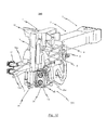
- the coupling head 1 Below the coupling head 1 is a line coupling 20; 220; 320 arranged. As will be described in detail below, the line coupling 20; 220; 320 designed such that it is automatically movable in the coupling process of the coupling head 1 with a matching counter-coupling head 1 'from a first, retracted position in a second, in the direction of the coupling plane T advanced position relative to the coupling head 1.
- the line coupling 20; 220; 320 is formed and arranged on the coupling head 1, that the front end portion of the line coupling 20; 220; 320 belonging coupling part 21; 21a, 21b in the second (advanced) position of the line coupling 20; 220; 320 in the intersection of the vertical coupling plane T and the vertical longitudinal sectional plane L of the coupling head 1 is located.
- the line coupling 20; 220; 320 arranged below the coupling head 1.
- the line coupling 20; 220; 320 by means of a support member 24 so attached to the coupling head 1, that the line coupling 20; 220; 320 is movable relative to the carrier element 24 in the longitudinal direction of the line plane between the first, retracted position and the second, advanced position.
- the support member 24 is rigidly connected in the illustrated embodiment via a threaded connection with the coupling head 1.
- corresponding bores 16 are provided for receiving screws in the carrier element 24, wherein the screws received in the bores 16 engage in corresponding threaded bores 13 provided on the coupling head 1.
- a screw connection it is of course also conceivable to fasten the carrier element 24 via a welded construction or otherwise to the coupling head 1.
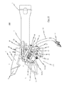
- the lever mechanism has a first lever member 30 which is pivotally received in the region of the small coupling claw 5 of the Willison profile in the form of a clutch pocket second Stirringungsorgan 9 about a rotational axis in a horizontal plane.
- the first lever member 30 is connected to a substantially vertically extending shaft 31, said shaft 31 defines the vertical axis of rotation of the first lever member 30.
- the second lever element is pivotable in the horizontal plane and on the one hand with the line coupling 20; 220; 320 and on the other hand connected to the shaft 31 such that upon pivoting of the first lever member 30, the resulting rotational movement is transmitted via the shaft 31 to the second lever member 32, consequently the line coupling 20; 220; 320 is moved from its first, retracted position in the direction of the coupling plane T to its second, advanced position.
- the second lever member 32 is formed as a pivotable in a horizontal plane pivot lever, which has a first lever arm 32a and a first lever arm 32a angled second lever arm 32b, wherein the vertical pivot axis of the second lever member 32 passes through the connecting portion between the first and the second lever arm 32a, 32b.
- the first lever arm 32a of the pivoting lever 32 is connected via a power transmission element 33, which - as in Fig. 5 or Fig. 11 shown - may be formed, for example, as a rod connected to the shaft 31.
- the free end region of the first lever arm 32a of the second lever element 32 designed as a pivoting lever is pivoted in a horizontal plane on a first end region of the force transmission element 33 and the second end region of the force transmission element 33 is pivoted on a lever 34 connected to the shaft 31 in a horizontal plane.
- the free end portion of the second lever arm 32b of the second lever member 32 formed as a pivot lever in a horizontal plane is pivotable on the line coupling 20; 220; 320 hinged.
- a lever mechanism can be used in the mechanical coupling process with a matching counter-coupling head 101 'on the first lever member 30 rotational movement to be used, the line coupling 20; 220; 320 to advance relative to the coupling head 1 in the direction of the coupling plane T.
- the tension spring 36 thereby counteracts a coupling action of the coupling head 1 with a matching counter-coupling head 1 'via the first lever member 30 transmitted to the shaft 31 torque.
- the coupling head 1 of the present invention is designed so that not only a mechanical connection between the coupling heads 1, 1 'is realized in the coupling process with a matching counter-coupling head 1', but also the line couplings 20, 20 '; 220, 20 '; 320, 20 ', and thus in particular the pneumatic brake lines and / or supply lines are automatically coupled together.
- the special construction of the coupling head 1 also allows the coupling head 1 to be coupled to the mating coupling head of a type AK 69e central buffer coupling.
- central buffer couplings of the type AK 69e are currently still in larger quantities, especially for iron ore transports in use.
- a coupling head of a type AK 69e center buffer coupling is not equipped with a mechanism comparable to the above-described lever mechanism, additional measures are provided in the coupling head 1 according to the present invention for coupling the air line coupling of the coupling coupling head of a type AK 69e center buffer coupling Counter-coupling head in the direction of the coupling plane T automatically advance.
- the coupling head 1 - as for example the representations in the FIGS. 1 to 3 . 9 and 10 can be removed - in the region of the small coupling claw 5 has a projecting in the direction of the coupling plane T area 7, which is hereinafter referred to as "horn".
- This horn 7 serves to slide and vertically align the mating coupling head of an AK 69e center buffer coupling when the mating coupling head is coupled to the coupling head 1 of the present invention.
- the horn 7 serves simultaneously for actuating a provided on the counter-coupling head pedal, with which the mating coupling head belonging air line coupling is driven in the direction of the coupling plane T.
- an ancestor of the line coupling 20; 220; To be able to bring 320 in the second position is - as shown in particular in the Fig. 5 .
- Fig. 7 and Fig. 11 can be removed - one with the line coupling 20; 220; 320 connected operating lever 22 is provided, which is pivotable in the horizontal plane for manual ancestor of the line coupling 20; 220; 320 in the second, in the direction of the coupling plane T advanced position.
- the line coupling 20; 220; 320 is arranged on the coupling head 1 such that the coupling part 21; 21a, 21b of the line coupling 20; 220; 320 is at the pipe height of the air line coupling of a coupling head type AK 69e.
- This allows a direct coupling of the coupling head 20 arranged on the coupling head 1 according to the invention; 220; 320 with the air line coupling of the counter-coupling head of a central buffer coupling type AK 69e.
- the line coupling 20; 220; 320 by hand via the actuating lever 22 to the already advanced air line coupling of the counter-coupling head of the central buffer coupling type AK 69e coupled and secured with a locking pin 23 in the coupled position (see. Fig. 8 ).
- This special design of the coupling head 1 according to the invention eliminates the need for an additional device in the form of a mixed air clutch, etc., to be used for coupling the air line couplings. Another advantage is the ease of use. The difficult engagement of a mixed air clutch in the below the central buffer coupling arranged and thus difficult to access air line at a central buffer coupling type AK 69e is eliminated.
- the line coupling 20; 220; 320 which is preferably arranged below the coupling head 1 at the line height of the pneumatic brake lines and / or supply lines of a central buffer coupling type AK 69e, in the illustrated embodiment by means of the already mentioned support member 24 in the longitudinal direction of the line plane relative to the support member 24 movable on Coupling head 1 attached.
- the line coupling 20; 220; 320 a carriage member 25 movable relative to the support member 24 in the longitudinal direction of the guide rail and a coupling member 21 resiliently supported in the carriage member 25; 21a, 21b, in the second advanced position of the line coupling 20; 220; 320, the front end portion of the coupling part 21; 21a, 21b is in the management level.
- the ancestor of the line coupling takes place automatically in the second position when the coupling head 1 is coupled with a matching counter-coupling head 1 '.
- a lever mechanism is used, which is actuated via the insertion movement of the coupling horn 8 'of the counter-coupling head 1' in the clutch pocket 9 of the coupling head 1 (see, in particular, the illustration in FIG Fig. 6 ).
- a first lever element 30 pivotably mounted in the coupling pocket 9 of the coupling head 1 in a horizontal plane is pivoted, with the resulting rotational movement via the shaft 31 to the pivot lever 32 pivotably mounted on the support element 24 in a horizontal plane and from there as linear movement on the longitudinal direction of the line plane relative to the carrier element 24 movable line coupling 20; 220; 320 is transmitted.
- the line coupling 20; 220; 320 are also moved forward manually by operating the operating lever 22 in the second position.
- the resiliently mounted in the carriage member 25 coupling part 21; 21a, 21b can - as the presentation in Fig. 4 for the embodiment as the air coupling part is removable - a coupling body 26 and a clutch body 26 held by the coupling body 26 and preferably releasably secured air coupling insert 27, wherein the air coupling insert 27 at its front, the coupling plane T end facing a mouthpiece seal 28; 28a, 28b.
- FIG Fig. 10 is removable for the coupling body 26 - 27 may be provided in the coupling body 26 instead of the air coupling insert 27, an electrical contact insert, which has electrical contacts 46.
- the air coupling insert 27 is designed as a tubular member which the mouthpiece seal 28; 28a, 28b carries.
- the air coupling insert 27 or the electrical contact insert 45 via a bracket 15; 15a, 15b is held in the coupling body 26.
- This arrangement also allows a change of the mouthpiece seal 28; 28a, 28b in the coupled state, so that the line coupling 20; 220; 320 can be easily maintained in the coupled state.
- the bracket 15; 15a; 15b and to pull the air coupling insert 27 to the rear from the substantially U-shaped support member 24.
- the installation of the air coupling insert 27 with a possibly renewed mouthpiece seal 28; 28a, 28b takes place in accordance with the reverse order.
- the bracket 15; 15a, 15b prevented in uncoupled state further rotation of the air coupling insert 27 or the electrical contact insert 45 about the longitudinal axis of the line coupling 20; 220; 320 and thus ensures that the line couplings 20, 20 '; 220, 20 '; 320, 20 'when engaging in aligned position to each other.
- the line coupling 20; 220; 320 a carriage member 25 movable relative to the support member 24 in the longitudinal direction of the rail plane, and a coupling member 21 resiliently supported in the carriage member 25; 21a, 21b.
- a spring element 19; 19a, 19b in the form of a compression spring used, which biases the coupling body 26 in the longitudinal direction of the line plane, wherein the spring element 19; 19a, 19b supported on the carriage member 25.
- the spring element 19; 19a, 19b is corresponding designed to provide a sufficient contact between the lines to be connected, for example, the mouthpiece seal 28 in the coupled state; 28a, 28b against the air pressure to a mouthpiece seal an air line coupling of a counter-coupling head to press or exert sufficient pressure on the contact surfaces of electrical contacts 46. Furthermore, the spring element 19 is similar; 19a, 19b, the longitudinal movement of the coupled couplings 20, 20 '; 220, 20 '; 320, 20 'in the context of occurring longitudinal play between the tensile and compressive contour in the Willison profile of the mechanically interconnected coupling heads 1, 1'aus.
- the coupling body 26 is now free to move radially and can follow the coupling movements freely, without distorting, and thus prevents lifting of the contact surfaces of two mutually coupled line couplings 20, 20 '; 220, 20 '; 320, 20 ', which may be, for example, sealing surfaces of an air line or the surfaces of electrical contacts 46 in electrical signal or supply lines.
- an air-conducting line 18 is connected to the rear end region of the air coupling attachment 27, this air-carrying line 18 being flexible as in conventional air lines and carrying at the end a brake coupling head 17 which is connected to a vehicle-side air line (not explicitly shown). can be connected.
- This construction also ensures that in dome operation with external couplings of the type Willision / SA-3, etc., the vehicle-side air lines can be coupled directly to each other.
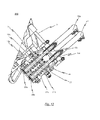
- Fig. 9 It is shown how a second coupling part 21b for an air line is arranged in a line coupling 220. Further views of this variant of the line coupling 220 are the Fig. 11 and 12 refer to.
- FIG. 10 Another variant in which the second coupling part 21b is a coupling part for an electrical line with an electrical contact insert 45 is Fig. 10 refer to.
- the main air reservoir line 41 (HB air line 41) with integrated into the designed coupling body 26.
- the arrangement of the HB air line 41 in the coupling body 26 takes place below the air-conducting line 18th
- the modular construction of the coupling body 26 also allows alternatively, as in Fig. 10 shown, or in addition to the HB air line 41, to install an optional interface for electrical data / signal transmission.
- an optional interface for electrical data / signal transmission For future developments of modern freight cars, the possibility of charge monitoring, fleet management, braking in braking position P (EP brake), etc. created.
- the coupling unit 220 in Fig. 9 has air coupling insert 27, which is provided with a corresponding receptacle for a mouthpiece seal 28b, on the side to be coupled, and on the other side facing the car body with an adapted for HB air line 41 end.
- the tubular air coupling extension 27 is arranged in a coupling body 26 which is equipped with centering member 29 for catching and aligning the line coupling 20 'of the counter-coupling.
- centering member 29 for catching and aligning the line coupling 20 'of the counter-coupling.
- To secure the components against displacement can serve, for example, a clamping pin connection 43.
- the coupling body 26 is in turn biased by compression spring 19b and braced with the provided for moving the coupling part 21b in the coupled position and uncoupled position carriage 25 with a screw connection with retaining nuts 44.
Landscapes
- Engineering & Computer Science (AREA)
- Mechanical Engineering (AREA)
- Vibration Prevention Devices (AREA)
- Quick-Acting Or Multi-Walled Pipe Joints (AREA)
- Transmission Devices (AREA)
- Hydraulic Clutches, Magnetic Clutches, Fluid Clutches, And Fluid Joints (AREA)
- Agricultural Machines (AREA)
- Ink Jet (AREA)
- Mutual Connection Of Rods And Tubes (AREA)
- Mechanical Control Devices (AREA)
Priority Applications (4)
| Application Number | Priority Date | Filing Date | Title |
|---|---|---|---|
| EP10172493A EP2371657B1 (fr) | 2010-03-19 | 2010-08-11 | Tête d'accouplement d'un attelage central automatique |
| EA201100098A EA020280B1 (ru) | 2010-03-19 | 2011-01-25 | Головка автоматической центральной буферной сцепки |
| CN2011100700664A CN102190004B (zh) | 2010-03-19 | 2011-03-18 | 自动中心缓冲车钩的钩头 |
| GEAP201112145A GEP20146130B (en) | 2010-03-19 | 2011-03-18 | Coupling head of automatic middle buffer |
Applications Claiming Priority (2)
| Application Number | Priority Date | Filing Date | Title |
|---|---|---|---|
| EP10157092 | 2010-03-19 | ||
| EP10172493A EP2371657B1 (fr) | 2010-03-19 | 2010-08-11 | Tête d'accouplement d'un attelage central automatique |
Publications (2)
| Publication Number | Publication Date |
|---|---|
| EP2371657A1 true EP2371657A1 (fr) | 2011-10-05 |
| EP2371657B1 EP2371657B1 (fr) | 2012-10-31 |
Family
ID=44063713
Family Applications (1)
| Application Number | Title | Priority Date | Filing Date |
|---|---|---|---|
| EP10172493A Not-in-force EP2371657B1 (fr) | 2010-03-19 | 2010-08-11 | Tête d'accouplement d'un attelage central automatique |
Country Status (5)
| Country | Link |
|---|---|
| EP (1) | EP2371657B1 (fr) |
| CN (1) | CN102190004B (fr) |
| EA (1) | EA020280B1 (fr) |
| GE (1) | GEP20146130B (fr) |
| UA (1) | UA101669C2 (fr) |
Cited By (2)
| Publication number | Priority date | Publication date | Assignee | Title |
|---|---|---|---|---|
| DE202014001206U1 (de) | 2014-02-12 | 2014-04-15 | Voith Patent Gmbh | Kupplungskopf einer automatischen Mittelpufferkupplung |
| DE102017113541A1 (de) | 2017-06-20 | 2018-12-20 | Voith Patent Gmbh | Kupplungskopf einer automatischen Mittelpufferkupplung |
Families Citing this family (3)
| Publication number | Priority date | Publication date | Assignee | Title |
|---|---|---|---|---|
| WO2016070788A1 (fr) * | 2014-11-04 | 2016-05-12 | 南车戚墅堰机车车辆工艺研究所有限公司 | Raccord de tuyau d'air pour coupleur à verrouillage étanche et composant de raccord de tuyau d'air pour coupleur à verrouillage étanche |
| DE102020107744A1 (de) * | 2020-03-20 | 2021-09-23 | Voith Patent Gmbh | Kupplungsanordnung |
| EP3922530A1 (fr) * | 2020-06-11 | 2021-12-15 | Dellner Couplers AB | Système de montage d'un module pneumatique et d'un module électrique dans une tête d'attelage d'un wagon de marchandises |
Citations (5)
| Publication number | Priority date | Publication date | Assignee | Title |
|---|---|---|---|---|
| FR1439832A (fr) * | 1963-11-22 | 1966-05-27 | Boirault App | Dispositif pour l'actionnement de conduites pneumatiques sur attelages automatiques de véhicules |
| CH425877A (de) * | 1961-10-14 | 1966-12-15 | Wsesojuznyi Nii Sheleznodorosh | Automatische Kupplung für Eisenbahnfahrzeuge |
| FR1484616A (fr) * | 1964-07-30 | 1967-06-16 | Boirault App | Dispositif de jonction des conduites pneumatiques pour attelages automatiques de véhicules de chemins de fer |
| DE1455242A1 (de) | 1962-03-19 | 1969-05-08 | Midland Ross Corp | Eisenbahnwagenkupplung |
| FR2101987A5 (fr) * | 1970-09-04 | 1972-03-31 | Knorr Bremse Gmbh |
Family Cites Families (5)
| Publication number | Priority date | Publication date | Assignee | Title |
|---|---|---|---|---|
| SU128039A1 (ru) * | 1959-05-18 | 1959-11-30 | В.В. Островский | Автоматическое устройство дл соединени тормозных воздушных магистралей железнодорожного подвижного состава |
| GB1295311A (fr) * | 1969-02-25 | 1972-11-08 | ||
| FI56509C (fi) * | 1972-12-13 | 1980-02-11 | Franco Belge Mat Chemin Fer | Automatisk koppling |
| DE4444881C1 (de) * | 1994-12-16 | 1996-02-22 | Bergische Stahlindustrie | Kupplungskopf für eine starre automatische Mittelkupplung von Schienenfahrzeugen |
| CN2933998Y (zh) * | 2006-08-25 | 2007-08-15 | 长春轨道客车股份有限公司 | 密接式车钩头 |
-
2010
- 2010-08-11 EP EP10172493A patent/EP2371657B1/fr not_active Not-in-force
-
2011
- 2011-01-12 UA UAA201100357A patent/UA101669C2/ru unknown
- 2011-01-25 EA EA201100098A patent/EA020280B1/ru not_active IP Right Cessation
- 2011-03-18 CN CN2011100700664A patent/CN102190004B/zh not_active Expired - Fee Related
- 2011-03-18 GE GEAP201112145A patent/GEP20146130B/en unknown
Patent Citations (5)
| Publication number | Priority date | Publication date | Assignee | Title |
|---|---|---|---|---|
| CH425877A (de) * | 1961-10-14 | 1966-12-15 | Wsesojuznyi Nii Sheleznodorosh | Automatische Kupplung für Eisenbahnfahrzeuge |
| DE1455242A1 (de) | 1962-03-19 | 1969-05-08 | Midland Ross Corp | Eisenbahnwagenkupplung |
| FR1439832A (fr) * | 1963-11-22 | 1966-05-27 | Boirault App | Dispositif pour l'actionnement de conduites pneumatiques sur attelages automatiques de véhicules |
| FR1484616A (fr) * | 1964-07-30 | 1967-06-16 | Boirault App | Dispositif de jonction des conduites pneumatiques pour attelages automatiques de véhicules de chemins de fer |
| FR2101987A5 (fr) * | 1970-09-04 | 1972-03-31 | Knorr Bremse Gmbh |
Cited By (4)
| Publication number | Priority date | Publication date | Assignee | Title |
|---|---|---|---|---|
| DE202014001206U1 (de) | 2014-02-12 | 2014-04-15 | Voith Patent Gmbh | Kupplungskopf einer automatischen Mittelpufferkupplung |
| WO2015121290A1 (fr) * | 2014-02-12 | 2015-08-20 | Voith Patent Gmbh | Tête de couplage d'un attelage automatique à tampon central |
| DE102017113541A1 (de) | 2017-06-20 | 2018-12-20 | Voith Patent Gmbh | Kupplungskopf einer automatischen Mittelpufferkupplung |
| WO2018233898A1 (fr) | 2017-06-20 | 2018-12-27 | Voith Patent Gmbh | Tête d'accouplement d'un attelage à tampon central automatique |
Also Published As
| Publication number | Publication date |
|---|---|
| EP2371657B1 (fr) | 2012-10-31 |
| EA020280B1 (ru) | 2014-10-30 |
| CN102190004B (zh) | 2013-12-04 |
| EA201100098A1 (ru) | 2011-12-30 |
| CN102190004A (zh) | 2011-09-21 |
| GEP20146130B (en) | 2014-08-11 |
| UA101669C2 (ru) | 2013-04-25 |
Similar Documents
| Publication | Publication Date | Title |
|---|---|---|
| EP4263318B1 (fr) | Attelage ferroviaire automatique et procédé de désaccouplement d'un attelage ferroviaire automatique | |
| EP4330110B1 (fr) | Attelage automatique de traction et procédé de dételage d'un attelage automatique de traction | |
| EP4330109B1 (fr) | Accouplement de traction automatique et procédé de désaccouplement d'un accouplement de traction automatique | |
| EP4263319B1 (fr) | Attelage de traction automatique | |
| EP2371657B1 (fr) | Tête d'accouplement d'un attelage central automatique | |
| EP2261098B1 (fr) | Attelage de transition pour véhicules ferroviaires | |
| WO2015121290A1 (fr) | Tête de couplage d'un attelage automatique à tampon central | |
| EP1149751B1 (fr) | Dispositif d' actionnement d' un adaptateur de longueur et/ou d' un dispositif de verrouillage d' un attelage automatique | |
| EP4486624B1 (fr) | Accouplement de train automatique, véhicule guidé sur rail comprenant un tel accouplement de train automatique, et procédé de désaccouplement de deux accouplements de train automatiques qui sont accouplés l'un à l'autre | |
| DE102018101996A1 (de) | Adapterteil zum Adaptieren eines Kupplungskopfes, Kupplungskopf mit Adapterteil sowie Verfahren zum Adaptieren eines Kupplungskopfes | |
| EP1602547B1 (fr) | Attelage central automatique pour un train composé de plusieurs véhicules ferroviaires. | |
| EP4183658B1 (fr) | Dispositif de verrouillage / déverrouillage d'un coupleur de véhicule ferroviaire | |
| DE102017113541A1 (de) | Kupplungskopf einer automatischen Mittelpufferkupplung | |
| EP4558375A1 (fr) | Couplage de train automatique, véhicule ferroviaire doté d'un couplage de train automatique, et procédé de couplage et de découplage d'un couplage de train automatique | |
| EP2371658B1 (fr) | Tête d'accouplement pour un véhicule sur rails | |
| EP1619101B1 (fr) | Accouplement pour le service et le remorquage, avec barre d'attelage articulée | |
| EP2390156B1 (fr) | Tête d'accouplement pour un véhicule ferroviaire | |
| EP1319569B1 (fr) | Dispositif d' accouplement, notamment pour un véhicule ferroviaire | |
| DE102006048778B4 (de) | Kupplungsvorrichtung zur Kupplung von zwei Fahrzeugen | |
| WO2025125569A1 (fr) | Attelage automatique de train et ensemble d'attelage | |
| WO2024061686A1 (fr) | Accouplement de train automatique | |
| DE102024132955A1 (de) | Automatische Zugkupplung und Kupplungsanordnung | |
| DE102024128133A1 (de) | Ventilbetätigungsvorrichtung für einen druckluftanschluss an einer automatischen mittelpufferkupplung | |
| DE102025144815A1 (de) | Kupplungsanordnung | |
| DE102025111211A1 (de) | Verfahren und Vorrichtung zum Entkuppeln von zwei miteinander gekuppelten automatischen Mittelpufferkupplungen eines Zugverbunds |
Legal Events
| Date | Code | Title | Description |
|---|---|---|---|
| PUAI | Public reference made under article 153(3) epc to a published international application that has entered the european phase |
Free format text: ORIGINAL CODE: 0009012 |
|
| 17P | Request for examination filed |
Effective date: 20110819 |
|
| AK | Designated contracting states |
Kind code of ref document: A1 Designated state(s): AL AT BE BG CH CY CZ DE DK EE ES FI FR GB GR HR HU IE IS IT LI LT LU LV MC MK MT NL NO PL PT RO SE SI SK SM TR |
|
| AX | Request for extension of the european patent |
Extension state: BA ME RS |
|
| GRAP | Despatch of communication of intention to grant a patent |
Free format text: ORIGINAL CODE: EPIDOSNIGR1 |
|
| RIN1 | Information on inventor provided before grant (corrected) |
Inventor name: SCHUELER, MARTIN |
|
| GRAS | Grant fee paid |
Free format text: ORIGINAL CODE: EPIDOSNIGR3 |
|
| GRAA | (expected) grant |
Free format text: ORIGINAL CODE: 0009210 |
|
| AK | Designated contracting states |
Kind code of ref document: B1 Designated state(s): AL AT BE BG CH CY CZ DE DK EE ES FI FR GB GR HR HU IE IS IT LI LT LU LV MC MK MT NL NO PL PT RO SE SI SK SM TR |
|
| REG | Reference to a national code |
Ref country code: GB Ref legal event code: FG4D Free format text: NOT ENGLISH Ref country code: CH Ref legal event code: EP |
|
| REG | Reference to a national code |
Ref country code: AT Ref legal event code: REF Ref document number: 581821 Country of ref document: AT Kind code of ref document: T Effective date: 20121115 |
|
| REG | Reference to a national code |
Ref country code: IE Ref legal event code: FG4D Free format text: LANGUAGE OF EP DOCUMENT: GERMAN |
|
| REG | Reference to a national code |
Ref country code: DE Ref legal event code: R096 Ref document number: 502010001546 Country of ref document: DE Effective date: 20121227 |
|
| REG | Reference to a national code |
Ref country code: RO Ref legal event code: EPE |
|
| REG | Reference to a national code |
Ref country code: SE Ref legal event code: TRGR |
|
| REG | Reference to a national code |
Ref country code: LT Ref legal event code: MG4D |
|
| REG | Reference to a national code |
Ref country code: NL Ref legal event code: VDEP Effective date: 20121031 |
|
| REG | Reference to a national code |
Ref country code: EE Ref legal event code: FG4A Ref document number: E007581 Country of ref document: EE Effective date: 20130103 |
|
| PG25 | Lapsed in a contracting state [announced via postgrant information from national office to epo] |
Ref country code: NL Free format text: LAPSE BECAUSE OF FAILURE TO SUBMIT A TRANSLATION OF THE DESCRIPTION OR TO PAY THE FEE WITHIN THE PRESCRIBED TIME-LIMIT Effective date: 20121031 Ref country code: IS Free format text: LAPSE BECAUSE OF FAILURE TO SUBMIT A TRANSLATION OF THE DESCRIPTION OR TO PAY THE FEE WITHIN THE PRESCRIBED TIME-LIMIT Effective date: 20130228 Ref country code: NO Free format text: LAPSE BECAUSE OF FAILURE TO SUBMIT A TRANSLATION OF THE DESCRIPTION OR TO PAY THE FEE WITHIN THE PRESCRIBED TIME-LIMIT Effective date: 20130131 Ref country code: LT Free format text: LAPSE BECAUSE OF FAILURE TO SUBMIT A TRANSLATION OF THE DESCRIPTION OR TO PAY THE FEE WITHIN THE PRESCRIBED TIME-LIMIT Effective date: 20121031 Ref country code: HR Free format text: LAPSE BECAUSE OF FAILURE TO SUBMIT A TRANSLATION OF THE DESCRIPTION OR TO PAY THE FEE WITHIN THE PRESCRIBED TIME-LIMIT Effective date: 20121031 |
|
| PG25 | Lapsed in a contracting state [announced via postgrant information from national office to epo] |
Ref country code: PT Free format text: LAPSE BECAUSE OF FAILURE TO SUBMIT A TRANSLATION OF THE DESCRIPTION OR TO PAY THE FEE WITHIN THE PRESCRIBED TIME-LIMIT Effective date: 20130228 Ref country code: PL Free format text: LAPSE BECAUSE OF FAILURE TO SUBMIT A TRANSLATION OF THE DESCRIPTION OR TO PAY THE FEE WITHIN THE PRESCRIBED TIME-LIMIT Effective date: 20121031 Ref country code: GR Free format text: LAPSE BECAUSE OF FAILURE TO SUBMIT A TRANSLATION OF THE DESCRIPTION OR TO PAY THE FEE WITHIN THE PRESCRIBED TIME-LIMIT Effective date: 20130201 Ref country code: SI Free format text: LAPSE BECAUSE OF FAILURE TO SUBMIT A TRANSLATION OF THE DESCRIPTION OR TO PAY THE FEE WITHIN THE PRESCRIBED TIME-LIMIT Effective date: 20121031 |
|
| PG25 | Lapsed in a contracting state [announced via postgrant information from national office to epo] |
Ref country code: SK Free format text: LAPSE BECAUSE OF FAILURE TO SUBMIT A TRANSLATION OF THE DESCRIPTION OR TO PAY THE FEE WITHIN THE PRESCRIBED TIME-LIMIT Effective date: 20121031 Ref country code: CZ Free format text: LAPSE BECAUSE OF FAILURE TO SUBMIT A TRANSLATION OF THE DESCRIPTION OR TO PAY THE FEE WITHIN THE PRESCRIBED TIME-LIMIT Effective date: 20121031 Ref country code: DK Free format text: LAPSE BECAUSE OF FAILURE TO SUBMIT A TRANSLATION OF THE DESCRIPTION OR TO PAY THE FEE WITHIN THE PRESCRIBED TIME-LIMIT Effective date: 20121031 Ref country code: BG Free format text: LAPSE BECAUSE OF FAILURE TO SUBMIT A TRANSLATION OF THE DESCRIPTION OR TO PAY THE FEE WITHIN THE PRESCRIBED TIME-LIMIT Effective date: 20130131 |
|
| PG25 | Lapsed in a contracting state [announced via postgrant information from national office to epo] |
Ref country code: IT Free format text: LAPSE BECAUSE OF FAILURE TO SUBMIT A TRANSLATION OF THE DESCRIPTION OR TO PAY THE FEE WITHIN THE PRESCRIBED TIME-LIMIT Effective date: 20121031 |
|
| PLBE | No opposition filed within time limit |
Free format text: ORIGINAL CODE: 0009261 |
|
| STAA | Information on the status of an ep patent application or granted ep patent |
Free format text: STATUS: NO OPPOSITION FILED WITHIN TIME LIMIT |
|
| 26N | No opposition filed |
Effective date: 20130801 |
|
| REG | Reference to a national code |
Ref country code: HU Ref legal event code: AG4A Ref document number: E017032 Country of ref document: HU |
|
| PG25 | Lapsed in a contracting state [announced via postgrant information from national office to epo] |
Ref country code: ES Free format text: LAPSE BECAUSE OF FAILURE TO SUBMIT A TRANSLATION OF THE DESCRIPTION OR TO PAY THE FEE WITHIN THE PRESCRIBED TIME-LIMIT Effective date: 20130211 |
|
| REG | Reference to a national code |
Ref country code: DE Ref legal event code: R097 Ref document number: 502010001546 Country of ref document: DE Effective date: 20130801 |
|
| PG25 | Lapsed in a contracting state [announced via postgrant information from national office to epo] |
Ref country code: CY Free format text: LAPSE BECAUSE OF FAILURE TO SUBMIT A TRANSLATION OF THE DESCRIPTION OR TO PAY THE FEE WITHIN THE PRESCRIBED TIME-LIMIT Effective date: 20121031 |
|
| BERE | Be: lapsed |
Owner name: VOITH PATENT G.M.B.H. Effective date: 20130831 |
|
| PG25 | Lapsed in a contracting state [announced via postgrant information from national office to epo] |
Ref country code: MC Free format text: LAPSE BECAUSE OF FAILURE TO SUBMIT A TRANSLATION OF THE DESCRIPTION OR TO PAY THE FEE WITHIN THE PRESCRIBED TIME-LIMIT Effective date: 20121031 |
|
| REG | Reference to a national code |
Ref country code: IE Ref legal event code: MM4A |
|
| PG25 | Lapsed in a contracting state [announced via postgrant information from national office to epo] |
Ref country code: BE Free format text: LAPSE BECAUSE OF NON-PAYMENT OF DUE FEES Effective date: 20130831 |
|
| PG25 | Lapsed in a contracting state [announced via postgrant information from national office to epo] |
Ref country code: IE Free format text: LAPSE BECAUSE OF NON-PAYMENT OF DUE FEES Effective date: 20130811 |
|
| PGFP | Annual fee paid to national office [announced via postgrant information from national office to epo] |
Ref country code: FI Payment date: 20140813 Year of fee payment: 5 Ref country code: RO Payment date: 20140724 Year of fee payment: 5 Ref country code: EE Payment date: 20140813 Year of fee payment: 5 |
|
| PGFP | Annual fee paid to national office [announced via postgrant information from national office to epo] |
Ref country code: LV Payment date: 20140813 Year of fee payment: 5 Ref country code: HU Payment date: 20140821 Year of fee payment: 5 |
|
| REG | Reference to a national code |
Ref country code: CH Ref legal event code: PL |
|
| PG25 | Lapsed in a contracting state [announced via postgrant information from national office to epo] |
Ref country code: CH Free format text: LAPSE BECAUSE OF NON-PAYMENT OF DUE FEES Effective date: 20140831 Ref country code: LI Free format text: LAPSE BECAUSE OF NON-PAYMENT OF DUE FEES Effective date: 20140831 |
|
| PG25 | Lapsed in a contracting state [announced via postgrant information from national office to epo] |
Ref country code: SM Free format text: LAPSE BECAUSE OF FAILURE TO SUBMIT A TRANSLATION OF THE DESCRIPTION OR TO PAY THE FEE WITHIN THE PRESCRIBED TIME-LIMIT Effective date: 20121031 |
|
| PG25 | Lapsed in a contracting state [announced via postgrant information from national office to epo] |
Ref country code: MT Free format text: LAPSE BECAUSE OF FAILURE TO SUBMIT A TRANSLATION OF THE DESCRIPTION OR TO PAY THE FEE WITHIN THE PRESCRIBED TIME-LIMIT Effective date: 20121031 Ref country code: TR Free format text: LAPSE BECAUSE OF FAILURE TO SUBMIT A TRANSLATION OF THE DESCRIPTION OR TO PAY THE FEE WITHIN THE PRESCRIBED TIME-LIMIT Effective date: 20121031 |
|
| PG25 | Lapsed in a contracting state [announced via postgrant information from national office to epo] |
Ref country code: LU Free format text: LAPSE BECAUSE OF NON-PAYMENT OF DUE FEES Effective date: 20130811 Ref country code: MK Free format text: LAPSE BECAUSE OF FAILURE TO SUBMIT A TRANSLATION OF THE DESCRIPTION OR TO PAY THE FEE WITHIN THE PRESCRIBED TIME-LIMIT Effective date: 20121031 |
|
| REG | Reference to a national code |
Ref country code: FR Ref legal event code: PLFP Year of fee payment: 6 |
|
| PGFP | Annual fee paid to national office [announced via postgrant information from national office to epo] |
Ref country code: GB Payment date: 20150819 Year of fee payment: 6 |
|
| PGFP | Annual fee paid to national office [announced via postgrant information from national office to epo] |
Ref country code: AT Payment date: 20150820 Year of fee payment: 6 Ref country code: FR Payment date: 20150820 Year of fee payment: 6 |
|
| REG | Reference to a national code |
Ref country code: EE Ref legal event code: MM4A Ref document number: E007581 Country of ref document: EE Effective date: 20150831 |
|
| PG25 | Lapsed in a contracting state [announced via postgrant information from national office to epo] |
Ref country code: EE Free format text: LAPSE BECAUSE OF NON-PAYMENT OF DUE FEES Effective date: 20150831 |
|
| PG25 | Lapsed in a contracting state [announced via postgrant information from national office to epo] |
Ref country code: LV Free format text: LAPSE BECAUSE OF NON-PAYMENT OF DUE FEES Effective date: 20150811 Ref country code: FI Free format text: LAPSE BECAUSE OF NON-PAYMENT OF DUE FEES Effective date: 20150811 Ref country code: HU Free format text: LAPSE BECAUSE OF NON-PAYMENT OF DUE FEES Effective date: 20150812 |
|
| PG25 | Lapsed in a contracting state [announced via postgrant information from national office to epo] |
Ref country code: RO Free format text: LAPSE BECAUSE OF NON-PAYMENT OF DUE FEES Effective date: 20150811 |
|
| REG | Reference to a national code |
Ref country code: AT Ref legal event code: MM01 Ref document number: 581821 Country of ref document: AT Kind code of ref document: T Effective date: 20160811 |
|
| GBPC | Gb: european patent ceased through non-payment of renewal fee |
Effective date: 20160811 |
|
| REG | Reference to a national code |
Ref country code: FR Ref legal event code: ST Effective date: 20170428 |
|
| PG25 | Lapsed in a contracting state [announced via postgrant information from national office to epo] |
Ref country code: AT Free format text: LAPSE BECAUSE OF NON-PAYMENT OF DUE FEES Effective date: 20160811 |
|
| PG25 | Lapsed in a contracting state [announced via postgrant information from national office to epo] |
Ref country code: GB Free format text: LAPSE BECAUSE OF NON-PAYMENT OF DUE FEES Effective date: 20160811 Ref country code: FR Free format text: LAPSE BECAUSE OF NON-PAYMENT OF DUE FEES Effective date: 20160831 |
|
| PG25 | Lapsed in a contracting state [announced via postgrant information from national office to epo] |
Ref country code: AL Free format text: LAPSE BECAUSE OF FAILURE TO SUBMIT A TRANSLATION OF THE DESCRIPTION OR TO PAY THE FEE WITHIN THE PRESCRIBED TIME-LIMIT Effective date: 20121031 |
|
| P01 | Opt-out of the competence of the unified patent court (upc) registered |
Effective date: 20230613 |
|
| PGFP | Annual fee paid to national office [announced via postgrant information from national office to epo] |
Ref country code: SE Payment date: 20230821 Year of fee payment: 14 Ref country code: DE Payment date: 20230821 Year of fee payment: 14 |
|
| REG | Reference to a national code |
Ref country code: DE Ref legal event code: R119 Ref document number: 502010001546 Country of ref document: DE |
|
| REG | Reference to a national code |
Ref country code: SE Ref legal event code: EUG |
|
| PG25 | Lapsed in a contracting state [announced via postgrant information from national office to epo] |
Ref country code: DE Free format text: LAPSE BECAUSE OF NON-PAYMENT OF DUE FEES Effective date: 20250301 |
|
| PG25 | Lapsed in a contracting state [announced via postgrant information from national office to epo] |
Ref country code: SE Free format text: LAPSE BECAUSE OF NON-PAYMENT OF DUE FEES Effective date: 20240812 |