EP2371688A1 - Structure de capot pour motocyclette - Google Patents
Structure de capot pour motocyclette Download PDFInfo
- Publication number
- EP2371688A1 EP2371688A1 EP11250281A EP11250281A EP2371688A1 EP 2371688 A1 EP2371688 A1 EP 2371688A1 EP 11250281 A EP11250281 A EP 11250281A EP 11250281 A EP11250281 A EP 11250281A EP 2371688 A1 EP2371688 A1 EP 2371688A1
- Authority
- EP
- European Patent Office
- Prior art keywords
- cowl
- portions
- rider
- movable
- pillion passenger
- Prior art date
- Legal status (The legal status is an assumption and is not a legal conclusion. Google has not performed a legal analysis and makes no representation as to the accuracy of the status listed.)
- Granted
Links
- 210000003127 knee Anatomy 0.000 claims abstract description 16
- 210000000689 upper leg Anatomy 0.000 claims abstract description 12
- 230000005540 biological transmission Effects 0.000 claims description 9
- 238000004804 winding Methods 0.000 claims description 9
- 210000002414 leg Anatomy 0.000 description 3
- 238000001816 cooling Methods 0.000 description 1
- 230000000694 effects Effects 0.000 description 1
- 238000005516 engineering process Methods 0.000 description 1
- 230000002708 enhancing effect Effects 0.000 description 1
- 239000002828 fuel tank Substances 0.000 description 1
- 210000004417 patella Anatomy 0.000 description 1
- XLYOFNOQVPJJNP-UHFFFAOYSA-N water Substances O XLYOFNOQVPJJNP-UHFFFAOYSA-N 0.000 description 1
Images





Classifications
-
- B—PERFORMING OPERATIONS; TRANSPORTING
- B62—LAND VEHICLES FOR TRAVELLING OTHERWISE THAN ON RAILS
- B62J—CYCLE SADDLES OR SEATS; AUXILIARY DEVICES OR ACCESSORIES SPECIALLY ADAPTED TO CYCLES AND NOT OTHERWISE PROVIDED FOR, e.g. ARTICLE CARRIERS OR CYCLE PROTECTORS
- B62J17/00—Weather guards for riders; Fairings or stream-lining parts not otherwise provided for
- B62J17/10—Ventilation or air guiding devices forming part of fairings
Definitions
- the present invention relates to an improvement in a motorcycle cowl structure.
- cowling also sometimes called a cowl
- cowl has a role of enhancing the external appearance of a vehicle and suppressing running-air flowing toward a rider.
- cowl structures have been proposed (see for example Fig. 2 of Japanese Utility Model Publication No. 3-27028 ).
- fixed flap portions (22) in the following, the numbers in parentheses denote reference numerals used in Japanese Utility Model Publication No. 3-27028
- a movable flap portion (23) are attached to a cowl main body (14) covering the front portion of a vehicle body.
- the fixed flap portion (22) allows running-air to flow on the side of a vehicle to prevent the running-air from hitting a rider.
- the rider can open the movable flap portion (23) to introduce running air from the gap of the opening movable flap portion (23), cooling her or his own leg.
- Japanese Utility Model Publication No. 3-27028 can arbitrarily control air flowing toward the rider.
- the motorcycle has a single-riding mode where a rider rides alone and a tandem-riding mode where a pillion passenger (also called a passenger) rides behind the rider.
- the movable flap portion (23) in Japanese Utility Model Publication No. 3-27028 is adapted to cover the rider but is not adapted to cover the knee cap, leg portion, waist and flank of the pillion passenger.
- the conventional cowl structure does not serve to shield a pillion passenger from the wind.
- a cowl structure for a motorcycle which can suppress running-air flowing toward a rider sitting on a rider seat and a pillion passenger sitting on a pillion passenger seat, comprising: left and right cowl main body portions adapted to prevent running-air from hitting knee portions, thighs, a waist and flanks of the rider; and left and right movable cowl portions provided on the respective left and right cowl main body portions so as to be movable in the direction of width of the vehicle, and which can be opened to prevent running-air from hitting knee portions, thighs, a waist and flanks of the pillion passenger.
- the rider When riding on the motorcycle alone, the rider closes the movable cowl portions.
- the cowl main body portions can prevent running-air from hitting the knee portions, thighs, waist and flanks of the rider.
- the movable cowl portions are closed, and so there is no need to worry about an increase in air resistance.
- the movable cowl portions When the rider and the pillion passenger are both riding on the motorcycle, the movable cowl portions are opened. Therefore, the movable cowl portions prevent running-air from hitting the knee portions, thighs, waist and flanks of the pillion passenger.
- the running-air flowing toward the rider and the pillion passenger can be suppressed in the case where the rider travels alone or in the case where a pillion passenger is also riding on the vehicle.
- the left movable cowl portion is interlocked with the right movable cowl portion.
- the left and right movable cowl portions are mechanically coupled to each other by means of a link mechanism.
- the link mechanism can have a simple configuration and a compact structure.
- the left and right movable cowl portions are mechanically interlinked with each other by means of a winding transmission mechanism.
- the winding transmission mechanism provides a configuration having satisfactory anti-vibration performance.
- the left and right movable cowl portions are provided with respective left and right actuators and can be opened and closed in conjunction with each other or individually.
- left and right movable cowl portions are provided with respective left and right actuators, a structure with a satisfactory left-right weight balance can be provided.
- the actuator is an electric motor or a cylinder unit.
- Such an actuator can be fitted inside the cowl compactly, thereby reducing the overall size of the structure.
- the actuator is a rack and pinion mechanism or a worm wheel mechanism driven by the electric motor.
- a motorcycle 10 is a straddle-ride type vehicle on which a rider and a pillion passenger ride by straddling a vehicle body.
- the motorcycle 10 includes a front fork 11 at a front portion of the vehicle, a front wheel 12 rotatably mounted at the lower portion of the front fork 11, and a rear wheel 13 at a rear lower portion of the vehicle. Further, the motorcycle 10 includes a fuel tank 14, a rider seat 15 on which the rider sits and the pillion passenger seat 16 on which a pillion passenger sits in this order from the upper centre to the rear of the vehicle.
- a front fender 18 covering the front wheel 12 from above is mounted to the front fork 11 so as to prevent mud and water from being splashed upward.
- a radiator 19 is disposed rearward of the front wheel 12.
- An exhaust pipe 20 extending rearward is installed on the left lateral surface of the lower portion of the vehicle body.
- a muffler 21 is joined to the rear portion of the exhaust pipe 20.
- a saddlebag 22 is disposed above the muffler 21.
- a cowl 30 is mounted to the vehicle body.
- the cowl 30 includes left and right main body portions 32, a front cowl 33, and a rear cowl 34.
- the left and right main body portions 32 are adapted to prevent running-air from hitting one or more of the knee portions (reference numeral 31 in Fig. 4 ), thighs (reference numeral 75 in Fig. 4 ), waist (reference numeral 76 in Fig. 4 ) and flanks (reference numeral 77 in Fig. 4 ) of the rider.
- the front cowl 33 is disposed at a front upper portion of the cowl main body portions 32 to cover the front upper portion of the vehicle body.
- the rear cowl 34 is disposed below the rider seat 15 and the pillion passenger seat 16 to cover the rear upper portion of the vehicle body.
- a windscreen 35 is mounted on the upper portion of the front cowl 33.
- the cowl main body portion 32 has a central portion which bends in the direction of width of the vehicle and is provided with main body side openings 36 at its upper portion.
- the main body side openings 36 have a triangular shape, tapered forwardly as viewed from the side of the vehicle body.
- the front ends of the left and right cowl main body portions 32 are opened to lead running-air toward a radiator 19.
- the cowl main body portion 32 is formed at a front portion with a plurality of elongate holes 38 (two, at upper and lower portions on one side in the figure).
- An arm 39 supported at its proximal end by the vehicle body projects from each elongate hole 38.
- the arm 39 is L-shaped so as to project in the direction of width of the vehicle from the external surface of the cowl main body portion 32 and then bend rearward. The arm 39 can be shifted back and forth in the elongate hole 38.
- Left and right movable cowl portions 41 are provided on the respective left and right cowl main body portions 32 so as to be movable in the direction of width of the vehicle.
- the movable cowl portions 41 are opened to prevent running-air from hitting one or more of the knee portions (reference numeral 40 in Fig. 5 ), thighs (reference numeral 78 in Fig. 5 ), waist (reference numeral 79 in Fig. 5 ) and flanks (reference numeral 80 in Fig. 5 ) of the pillion passenger.
- Each movable cowl portion 41 is shaped so as to fit along the external surface of the cowl main body portion 32 and has a trapezoidal shape as viewed from the side of the vehicle.
- the upper edge and lower edge of the movable cowl portion 41 are formed to extend in the back and forth direction of the vehicle.
- the movable cowl portion 41 has a front edge formed to extend in a vertical direction and a rear edge tilted downward as it goes toward the rear of the vehicle.
- the movable cowl portion 41 is provided with a side opening 42 having almost the same shape as that of the main body side opening 36.
- the side opening 42 is designed to conform with the main body side opening 36 in the state where the movable cowl portion 41 overlaps the cowl main body portion 32 (in the state where the movable cowl portion 41 is closed).
- a front portion of the movable cowl portion 41 is fastened to the end portions of the upper and lower arms 39 by means of a plurality of bolts 44 (two in the figure).
- the movable cowl portion 41 can be opened and closed by movement of the end portion of the arm 39.
- cowl structure of the present invention is next described in detail with reference to Fig. 2 .
- support shafts 45 are provided on the vehicle body, and an arm 39 is turnably attached to each of the support shafts 45.
- the left and right movable cowl portions 41 are mechanically interlinked with each other by means of a link mechanism 46.
- the movable cowl portions 41 are driven by a worm wheel mechanism 47.
- Each support shaft 45 supports two (upper and lower) arms (reference numeral 39 in Fig. 1 ), only one of which is shown in Fig. 2 .
- the link mechanism 46 includes swing portions 48 installed on the corresponding proximal portions of the arms 39 and a connecting bar 50 connecting the left and right swing portions 48 together.
- the worm wheel mechanism 47 includes an operating shaft 52 supported by the right side of the vehicle body via bearings 51; a worm portion 53 provided on the operating shaft 52; and a wheel portion 54 installed on the right swing portion 48 and meshing with the worm portion 53.
- a handle 56 is attached to the operating shaft 52.
- Fig. 2 illustrates the state where the left and right movable cowl portions 41 are closed.
- a rider turns the handle 56 to turn the right swing portion 48 in the direction of arrow (1) via the worm portion 53 and the wheel portion 54.
- the turning of the right swing portion 48 also turns the left swing portion 48 via the connecting bar 50.
- the turning of the left and right swing portions 48 opens the left and right swing cowl portions 41 in the direction of arrow (2) via the corresponding left and right arms 39.
- the worm wheel mechanism may instead be installed on the left swing portion 48 and the right movable cowl portion 41 may be made to interlock with the left movable cowl portion 41.
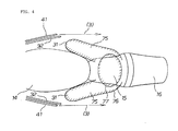
- Fig. 4 illustrates a travelling vehicle on which a single rider is mounted as viewed from above
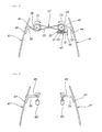
- Fig. 5 illustrates a travelling vehicle on which the rider and a pillion passenger are mounted as viewed from above.
- the rider adjusts the handle (reference numeral 56 in Fig. 2 ) to bring the left and right movable cowl portions 41 into the state of being closed toward the cowl main body portion 32.
- the cowl main body portions 32 allow running-air to flow on the external sides of the rider's knee portions 31 as illustrated with arrows (3), i.e., so as not to hit the knee portions 31, thighs 75, waist 76 and flanks 77 of the rider.
- the handle (reference 56 in Fig. 2 ) is adjusted to open the left and right movable cowl portions 41.
- the opened left and right movable cowl portions 41 allow running-air to flow on the external sides of the knee portions 40 of the pillion passenger as illustrated in arrows (4), i.e., so as not to hit the knee portion 40, thighs 78, waist 79 and flanks 80 of the pillion passenger.
- left and right movable cowl portions 41 are mechanically interlinked with each other so that they move at the same time, their behaviour becomes more reliable. Since the link mechanism has a simple configuration, its structure can be made compact.
- FIG. 6 A second embodiment of the present invention is next described with reference to Fig. 6 .
- the left and right arms 39 are mechanically interlinked with each other by means of a winding transmission mechanism 57.
- the other parts of the mechanism are the same as in Fig. 2 , and therefore their detailed description is omitted.
- the winding transmission mechanism 57 includes pulleys 58 provided on the left and right support shafts 45, and a cross-wound wire 59 wound around the left and right pulleys 59.
- a belt may be used in place of the wire.
- FIG. 7 A third embodiment of the present invention is next described with reference to Fig. 7 .
- an electric motor 60 is installed on each of the left and right movable cowl portions 41, without the use of the link mechanism. Other details are the same as in Fig. 2 , and so their detailed description is omitted.
- the electric motor 60 is connected to the proximal portion of the arm 39.
- the movable cowl portion 41 is opened and closed through the turning of the arm 39 by the electric motor 60.
- the left and right movable cowl portions 41 are each provided with the respective left and right electric motors 60; therefore, the structure is simpler than the structure provided with the interlink mechanism. Further, the structure has a better left-right weight balance.
- the left and right electric motors 60 may electrically be controlled in an interlinked manner.
- FIG. 8 A fourth embodiment of the present invention is next described with reference to Fig. 8 .
- the left and right movable cowl portions 41 are provided with respective cylinder units 62.
- the other details are the same as in Fig. 7 , and therefore their detailed description is omitted.
- Each cylinder unit 62 is installed such that its axial direction extends in the direction of width of the vehicle.
- a push rod 63 of each of the cylinder units 62 is connected to the rear portion of the movable cowl portion 41 via a connecting rod 50 and a connecting pin 64.
- Each push rod 63 is reciprocated in the vehicle-width direction to open and close the movable cowl portion 41 by rotation around the support shaft 45.
- left and right movable cowl portions 41 are provided with the respective left and right cylinder units 62, the structure is simpler than that provided with the interlinking mechanism. In addition, a better left-right weight balance can be achieved.
- FIG. 9 A fifth embodiment of the present invention is next described with reference to Fig. 9 .
- a rack and pinion mechanism 65 is installed in place of the cylinder units.
- Other details are the same as in Fig. 8 , and so a detailed description is omitted.
- Left and right racks 66 are installed on the vehicle body.
- the racks 66 are housed in respective cases 68 so as to be movable in the direction of width of the vehicle.
- the left and right racks 66 are each connected to the rear portion of the movable cowl portion 41 via a connecting rod 50 and a connecting pin 64 and to an electric motor 60 via a pinion 69.
- the racks 66 are each moved in the direction of width of the vehicle by the electric motor 60 to open and close the movable cowl portion 41 by rotation around the support shaft 45.
- FIG. 10 A sixth embodiment of the present invention is next described with reference to Fig. 10 .
- front and rear left and right support shafts 45 (four in total), are installed on a vehicle body. Arms 39 are supported by respective front left and right support shafts 48. On the other hand, rear arms 70 are supported by respective rear support shafts 45 on the rear side via corresponding swing portions 48 and pins 71. An electric motor 60 is connected to the right swing portion 48.
- the left and right arms 39 are connected to the left and right rear arms 70 by means of a winding transmission mechanism 57.
- the winding transmission mechanism 57 includes: pulleys 58 installed on the respective rear left and right support shafts 45; two-step pulleys 72 installed on the front left and right support shafts 45; parallel-wound wires 73 each wound around a pulley 58 and a two-stage pulley 72; and the cross-wound wire 59 wound around the left and right two-stage pulleys 72.
- the drive force of the electric motor 60 is transmitted to the left and right arms 39 and the left and right rear arms 70 by means of the winding transmission mechanism 57.
- the left and right arms 39 and the left and right rear arms 70 are turned around the corresponding support shafts 45 in conjunction with each other.
- the turning of the left and right arms 39 and left and right rear arms 70 opens and closes the left and right movable cowl portions 41.
- the movable cowl portions 41 can provide stable opening and closing operation.
- cowl structure is applied to a straddle-ride type motorcycle in the present embodiment.
- cowl structure could equally well be applied to a scooter-type motorcycle configured such that a pillion passenger rides thereon behind a rider, as the cowl structure of the present invention is suitable for straddle-ride type vehicles.
Landscapes
- Engineering & Computer Science (AREA)
- Mechanical Engineering (AREA)
- Automatic Cycles, And Cycles In General (AREA)
- Body Structure For Vehicles (AREA)
Applications Claiming Priority (1)
| Application Number | Priority Date | Filing Date | Title |
|---|---|---|---|
| JP2010070314A JP5486978B2 (ja) | 2010-03-25 | 2010-03-25 | 自動二輪車のカウル構造 |
Publications (2)
| Publication Number | Publication Date |
|---|---|
| EP2371688A1 true EP2371688A1 (fr) | 2011-10-05 |
| EP2371688B1 EP2371688B1 (fr) | 2015-11-04 |
Family
ID=43928939
Family Applications (1)
| Application Number | Title | Priority Date | Filing Date |
|---|---|---|---|
| EP11250281.0A Not-in-force EP2371688B1 (fr) | 2010-03-25 | 2011-03-10 | Structure de capot pour motocyclette |
Country Status (4)
| Country | Link |
|---|---|
| US (1) | US8517449B2 (fr) |
| EP (1) | EP2371688B1 (fr) |
| JP (1) | JP5486978B2 (fr) |
| ES (1) | ES2559942T3 (fr) |
Cited By (4)
| Publication number | Priority date | Publication date | Assignee | Title |
|---|---|---|---|---|
| EP2889207A1 (fr) * | 2013-12-25 | 2015-07-01 | Yamaha Hatsudoki Kabushiki Kaisha | Motocyclette |
| WO2015070216A3 (fr) * | 2013-11-11 | 2015-07-30 | Polaris Industries Inc. | Véhicule à deux roues |
| US9216789B2 (en) | 2012-11-12 | 2015-12-22 | Indian Motorcycle International, LLC | Two-wheeled vehicle |
| US10899412B2 (en) | 2018-09-05 | 2021-01-26 | Indian Motorcycle International, LLC | Two wheeled vehicle |
Families Citing this family (24)
| Publication number | Priority date | Publication date | Assignee | Title |
|---|---|---|---|---|
| US9573645B2 (en) * | 2013-11-15 | 2017-02-21 | Kawasaki Jukogyo Kabushiki Kaisha | Motorcycle |
| WO2015152840A1 (fr) * | 2014-03-31 | 2015-10-08 | Honda Motor Company Limited | Structure de garniture avant de motocyclette |
| JP1545483S (fr) * | 2015-06-19 | 2016-03-14 | ||
| JP1545073S (fr) * | 2015-07-08 | 2016-03-07 | ||
| JP1557432S (fr) * | 2015-12-24 | 2016-08-29 | ||
| JP1568691S (fr) * | 2016-05-27 | 2017-02-06 | ||
| JP1585663S (fr) * | 2017-03-24 | 2018-01-09 | ||
| JP1598943S (fr) * | 2017-09-15 | 2018-03-05 | ||
| JP1612279S (fr) * | 2018-01-23 | 2018-08-27 | ||
| TWI653180B (zh) * | 2018-01-31 | 2019-03-11 | 光陽工業股份有限公司 | 電動車的電池盒構造 |
| JP6708696B2 (ja) * | 2018-04-27 | 2020-06-10 | 本田技研工業株式会社 | 鞍乗り型車両のカウル構造 |
| JP1621513S (fr) * | 2018-05-31 | 2019-01-07 | ||
| JP1621510S (fr) * | 2018-05-31 | 2019-01-07 | ||
| JP1621509S (fr) * | 2018-05-31 | 2019-01-07 | ||
| JP6806747B2 (ja) * | 2018-09-28 | 2021-01-06 | 本田技研工業株式会社 | 鞍乗り型車両のカウル構造 |
| JP1649577S (fr) * | 2019-06-07 | 2020-01-14 | ||
| ES2800071B2 (es) * | 2019-06-21 | 2021-06-23 | Univ Huelva | Sistema de anclaje del carenado al chasis de una motocicleta |
| USD918785S1 (en) * | 2019-08-05 | 2021-05-11 | Kawasaki Jukogyo Kabushiki Kaisiia | Fairing for a motorcycle |
| DE102020125060A1 (de) * | 2020-09-25 | 2022-03-31 | Bayerische Motoren Werke Aktiengesellschaft | Kraftrad mit verstellbarem Luftleitelement |
| IT202100006029A1 (it) * | 2021-03-15 | 2022-09-15 | Piaggio & C Spa | Motociclo con aerodinamica attiva |
| CN114560032B (zh) * | 2022-04-20 | 2025-12-12 | 段镇企 | 一种摩托车整流头罩 |
| IT202200017922A1 (it) * | 2022-08-31 | 2024-03-02 | Pili Giorgio | Soluzioni aerodinamiche attive,regolabili e semi-regolabili,per motocicli stradali naked e sportivi,con coinvolgimento di nuove geometrie sulla carena e vari dispositivi di controllo |
| DE202023103889U1 (de) * | 2023-07-12 | 2023-07-26 | Ktm Ag | Seitenverkleidung und damit versehenes Motorrad |
| USD1075584S1 (en) * | 2023-08-11 | 2025-05-20 | Qianqian Wu | Pair of motorcycle water tank protective covers |
Citations (4)
| Publication number | Priority date | Publication date | Assignee | Title |
|---|---|---|---|---|
| DE3420352A1 (de) * | 1984-05-30 | 1985-12-05 | Bayerische Motoren Werke AG, 8000 München | Motorradverkleidung |
| JPH0327028U (fr) | 1989-07-27 | 1991-03-19 | ||
| EP1170201A2 (fr) * | 2000-07-04 | 2002-01-09 | Bayerische Motoren Werke Aktiengesellschaft | Dispositif de réglage de pièces de véhicule en fonction des conditions climatiques |
| EP1514782A2 (fr) | 2003-09-12 | 2005-03-16 | Kawasaki Jukogyo Kabushiki Kaisha | Système de réglage du débit d'air pour motocyclette |
Family Cites Families (31)
| Publication number | Priority date | Publication date | Assignee | Title |
|---|---|---|---|---|
| US2555146A (en) * | 1948-09-07 | 1951-05-29 | Sr Clyde H Mcnamee | Ventilating deflector |
| US4010976A (en) * | 1976-02-13 | 1977-03-08 | Shields William D | Motorcycle fairing |
| GB2101546B (en) * | 1981-05-18 | 1985-01-09 | Honda Motor Co Ltd | Motorcycle fairings |
| JPS5948280A (ja) * | 1982-09-11 | 1984-03-19 | 本田技研工業株式会社 | 自動二輪車等のエンジン冷却装置 |
| US4650204A (en) * | 1982-12-17 | 1987-03-17 | Bothwell Peter W | Motorcycle with buffers to protect user's legs |
| US4479676A (en) * | 1983-05-17 | 1984-10-30 | Hayes Kenneth W | Method and apparatus for channelling air through a motorcycle fairing |
| JPS6055526U (ja) * | 1983-09-26 | 1985-04-18 | 本田技研工業株式会社 | 自動二輪車 |
| JPS6067224A (ja) * | 1983-09-26 | 1985-04-17 | Honda Motor Co Ltd | 自動二輪車 |
| JPS6159187U (fr) * | 1984-09-14 | 1986-04-21 | ||
| US4615556A (en) * | 1985-02-14 | 1986-10-07 | Drag Specialties, Inc. | Windshield vent wing and hinge |
| JPH0327028Y2 (fr) * | 1986-05-02 | 1991-06-11 | ||
| US4776422A (en) * | 1986-05-30 | 1988-10-11 | Honda Giken Kogyo Kabushiki Kaisha | Motorcycle with fairing |
| JPS63101185A (ja) * | 1986-10-17 | 1988-05-06 | 本田技研工業株式会社 | 自動二輪車 |
| US4887688A (en) * | 1987-08-06 | 1989-12-19 | Honda Giken Kogyo Kabushiki Kaisha | Motorcycle |
| JPS6483481A (en) * | 1987-09-25 | 1989-03-29 | Honda Motor Co Ltd | Motorcycle |
| US4964484A (en) * | 1989-04-06 | 1990-10-23 | Buell Motor Company, Inc. | Motorcycle fairing |
| JP3549162B2 (ja) * | 1990-06-18 | 2004-08-04 | 本田技研工業株式会社 | 自動2輪車用フェアリング |
| JPH0456690A (ja) * | 1990-06-26 | 1992-02-24 | Yamaha Motor Co Ltd | 自動二輪車のレッグシールド装置 |
| JP3809619B2 (ja) * | 1996-11-07 | 2006-08-16 | ヤマハ発動機株式会社 | スクータ型車両 |
| JP2006240315A (ja) * | 2003-05-20 | 2006-09-14 | Yamaha Motor Co Ltd | 鞍乗型車両 |
| JP2006069404A (ja) * | 2004-09-03 | 2006-03-16 | Yamaha Motor Co Ltd | 車両 |
| JP2006143176A (ja) * | 2004-10-20 | 2006-06-08 | Yamaha Motor Co Ltd | フロントカウル及びそれを備えた車両 |
| JP4584781B2 (ja) * | 2005-06-15 | 2010-11-24 | 本田技研工業株式会社 | 自動二輪車用カウリング構造 |
| JP2007062643A (ja) * | 2005-09-01 | 2007-03-15 | Yamaha Motor Co Ltd | 自動二輪車の車体冷却構造および自動二輪車 |
| JP4842066B2 (ja) * | 2006-04-14 | 2011-12-21 | ヤマハ発動機株式会社 | 車両 |
| JP4856485B2 (ja) * | 2006-07-14 | 2012-01-18 | 本田技研工業株式会社 | 自動二輪車のカウリング構造 |
| JP5156507B2 (ja) * | 2008-07-04 | 2013-03-06 | 川崎重工業株式会社 | 車両用レッグシールド |
| JP2011136612A (ja) * | 2009-12-28 | 2011-07-14 | Honda Motor Co Ltd | 車両のリッド構造 |
| ES2592935T3 (es) * | 2010-02-09 | 2016-12-02 | Suzuki Motor Corporation | Motocicleta |
| JP5879064B2 (ja) * | 2011-07-28 | 2016-03-08 | 本田技研工業株式会社 | 鞍乗型車両 |
| JP5707290B2 (ja) * | 2011-09-28 | 2015-04-30 | 本田技研工業株式会社 | 鞍乗型車両 |
-
2010
- 2010-03-25 JP JP2010070314A patent/JP5486978B2/ja not_active Expired - Fee Related
-
2011
- 2011-03-10 EP EP11250281.0A patent/EP2371688B1/fr not_active Not-in-force
- 2011-03-10 ES ES11250281.0T patent/ES2559942T3/es active Active
- 2011-03-22 US US13/053,362 patent/US8517449B2/en not_active Expired - Fee Related
Patent Citations (4)
| Publication number | Priority date | Publication date | Assignee | Title |
|---|---|---|---|---|
| DE3420352A1 (de) * | 1984-05-30 | 1985-12-05 | Bayerische Motoren Werke AG, 8000 München | Motorradverkleidung |
| JPH0327028U (fr) | 1989-07-27 | 1991-03-19 | ||
| EP1170201A2 (fr) * | 2000-07-04 | 2002-01-09 | Bayerische Motoren Werke Aktiengesellschaft | Dispositif de réglage de pièces de véhicule en fonction des conditions climatiques |
| EP1514782A2 (fr) | 2003-09-12 | 2005-03-16 | Kawasaki Jukogyo Kabushiki Kaisha | Système de réglage du débit d'air pour motocyclette |
Cited By (10)
| Publication number | Priority date | Publication date | Assignee | Title |
|---|---|---|---|---|
| US9216789B2 (en) | 2012-11-12 | 2015-12-22 | Indian Motorcycle International, LLC | Two-wheeled vehicle |
| US9394859B2 (en) | 2012-11-12 | 2016-07-19 | Indian Motorcycle International, LLC | Two-wheeled vehicle |
| US9550541B2 (en) | 2012-11-12 | 2017-01-24 | Indian Motorcycle International, LLC | Two-wheeled vehicle |
| US9958111B2 (en) | 2012-11-12 | 2018-05-01 | Indian Motorcycle International, LLC | Two-wheeled vehicle |
| US10183717B2 (en) | 2012-11-12 | 2019-01-22 | Indian Motorcycle International, LLC | Two-wheeled vehicle |
| WO2015070216A3 (fr) * | 2013-11-11 | 2015-07-30 | Polaris Industries Inc. | Véhicule à deux roues |
| US10760730B2 (en) | 2013-11-11 | 2020-09-01 | Indian Motorcycle International, LLC | Two-wheeled vehicle |
| US11427277B2 (en) | 2013-11-11 | 2022-08-30 | Indian Motorcycle International, LLC | Two-wheeled vehicle |
| EP2889207A1 (fr) * | 2013-12-25 | 2015-07-01 | Yamaha Hatsudoki Kabushiki Kaisha | Motocyclette |
| US10899412B2 (en) | 2018-09-05 | 2021-01-26 | Indian Motorcycle International, LLC | Two wheeled vehicle |
Also Published As
| Publication number | Publication date |
|---|---|
| EP2371688B1 (fr) | 2015-11-04 |
| JP2011201409A (ja) | 2011-10-13 |
| US20110233956A1 (en) | 2011-09-29 |
| US8517449B2 (en) | 2013-08-27 |
| ES2559942T3 (es) | 2016-02-16 |
| JP5486978B2 (ja) | 2014-05-07 |
Similar Documents
| Publication | Publication Date | Title |
|---|---|---|
| EP2371688B1 (fr) | Structure de capot pour motocyclette | |
| JP4619819B2 (ja) | 不整地走行車両のパワーステアリングシステム | |
| US20160318579A1 (en) | Electric vehicle | |
| EP3072791B1 (fr) | Véhicule de type à enfourcher | |
| CA2944815C (fr) | Vehicule de type a sellette dote d'un support de coussin et d'une structure de garde-boue co-fixes | |
| JP7149161B2 (ja) | 鞍乗り型電動車両 | |
| EP1304284B1 (fr) | Vehicule monté à califourchon | |
| JP5727911B2 (ja) | 鞍乗型車両の後部構造 | |
| EP3378751A1 (fr) | Structure de support de garde-boue arrière de véhicule à selle | |
| JP6855514B2 (ja) | 鞍乗り型車両 | |
| JP4684681B2 (ja) | 鞍乗り型不整地走行車両のパワーステアリングシステム | |
| EP1972534B1 (fr) | Motocyclette | |
| JP2019147503A (ja) | 鞍乗り型車両 | |
| JP2006232061A (ja) | 鞍乗り型不整地走行車両 | |
| JP5600669B2 (ja) | 鞍乗型電動車両の車体構造 | |
| JP6623668B2 (ja) | 鞍乗り型車両のエアクリーナ構造 | |
| JP6088965B2 (ja) | 小型車両の吸気装置 | |
| TWI415763B (zh) | Hybrid electric hybrid vehicles | |
| JP5629654B2 (ja) | 鞍乗型車両 | |
| JP2014145349A (ja) | 自動二輪車 | |
| US20250206410A1 (en) | Saddle riding type electric vehicle | |
| EP2502816B1 (fr) | Structure de cadre pour véhicule à monture de selle | |
| JP2005088641A (ja) | 自動二輪車の整流機構 | |
| JP6094904B2 (ja) | 自動二輪車 | |
| JP7738613B2 (ja) | 鞍乗り型電動車両 |
Legal Events
| Date | Code | Title | Description |
|---|---|---|---|
| PUAI | Public reference made under article 153(3) epc to a published international application that has entered the european phase |
Free format text: ORIGINAL CODE: 0009012 |
|
| AK | Designated contracting states |
Kind code of ref document: A1 Designated state(s): AL AT BE BG CH CY CZ DE DK EE ES FI FR GB GR HR HU IE IS IT LI LT LU LV MC MK MT NL NO PL PT RO RS SE SI SK SM TR |
|
| AX | Request for extension of the european patent |
Extension state: BA ME |
|
| 17P | Request for examination filed |
Effective date: 20120326 |
|
| GRAP | Despatch of communication of intention to grant a patent |
Free format text: ORIGINAL CODE: EPIDOSNIGR1 |
|
| INTG | Intention to grant announced |
Effective date: 20150804 |
|
| GRAS | Grant fee paid |
Free format text: ORIGINAL CODE: EPIDOSNIGR3 |
|
| GRAA | (expected) grant |
Free format text: ORIGINAL CODE: 0009210 |
|
| AK | Designated contracting states |
Kind code of ref document: B1 Designated state(s): AL AT BE BG CH CY CZ DE DK EE ES FI FR GB GR HR HU IE IS IT LI LT LU LV MC MK MT NL NO PL PT RO RS SE SI SK SM TR |
|
| REG | Reference to a national code |
Ref country code: GB Ref legal event code: FG4D |
|
| REG | Reference to a national code |
Ref country code: CH Ref legal event code: EP |
|
| REG | Reference to a national code |
Ref country code: AT Ref legal event code: REF Ref document number: 758979 Country of ref document: AT Kind code of ref document: T Effective date: 20151115 |
|
| REG | Reference to a national code |
Ref country code: IE Ref legal event code: FG4D |
|
| REG | Reference to a national code |
Ref country code: DE Ref legal event code: R096 Ref document number: 602011021115 Country of ref document: DE |
|
| REG | Reference to a national code |
Ref country code: FR Ref legal event code: PLFP Year of fee payment: 6 |
|
| REG | Reference to a national code |
Ref country code: ES Ref legal event code: FG2A Ref document number: 2559942 Country of ref document: ES Kind code of ref document: T3 Effective date: 20160216 |
|
| REG | Reference to a national code |
Ref country code: NL Ref legal event code: MP Effective date: 20151104 |
|
| REG | Reference to a national code |
Ref country code: LT Ref legal event code: MG4D |
|
| REG | Reference to a national code |
Ref country code: AT Ref legal event code: MK05 Ref document number: 758979 Country of ref document: AT Kind code of ref document: T Effective date: 20151104 |
|
| PG25 | Lapsed in a contracting state [announced via postgrant information from national office to epo] |
Ref country code: NO Free format text: LAPSE BECAUSE OF FAILURE TO SUBMIT A TRANSLATION OF THE DESCRIPTION OR TO PAY THE FEE WITHIN THE PRESCRIBED TIME-LIMIT Effective date: 20160204 Ref country code: LT Free format text: LAPSE BECAUSE OF FAILURE TO SUBMIT A TRANSLATION OF THE DESCRIPTION OR TO PAY THE FEE WITHIN THE PRESCRIBED TIME-LIMIT Effective date: 20151104 Ref country code: NL Free format text: LAPSE BECAUSE OF FAILURE TO SUBMIT A TRANSLATION OF THE DESCRIPTION OR TO PAY THE FEE WITHIN THE PRESCRIBED TIME-LIMIT Effective date: 20151104 Ref country code: HR Free format text: LAPSE BECAUSE OF FAILURE TO SUBMIT A TRANSLATION OF THE DESCRIPTION OR TO PAY THE FEE WITHIN THE PRESCRIBED TIME-LIMIT Effective date: 20151104 Ref country code: IS Free format text: LAPSE BECAUSE OF FAILURE TO SUBMIT A TRANSLATION OF THE DESCRIPTION OR TO PAY THE FEE WITHIN THE PRESCRIBED TIME-LIMIT Effective date: 20160304 |
|
| PG25 | Lapsed in a contracting state [announced via postgrant information from national office to epo] |
Ref country code: PL Free format text: LAPSE BECAUSE OF FAILURE TO SUBMIT A TRANSLATION OF THE DESCRIPTION OR TO PAY THE FEE WITHIN THE PRESCRIBED TIME-LIMIT Effective date: 20151104 Ref country code: RS Free format text: LAPSE BECAUSE OF FAILURE TO SUBMIT A TRANSLATION OF THE DESCRIPTION OR TO PAY THE FEE WITHIN THE PRESCRIBED TIME-LIMIT Effective date: 20151104 Ref country code: FI Free format text: LAPSE BECAUSE OF FAILURE TO SUBMIT A TRANSLATION OF THE DESCRIPTION OR TO PAY THE FEE WITHIN THE PRESCRIBED TIME-LIMIT Effective date: 20151104 Ref country code: PT Free format text: LAPSE BECAUSE OF FAILURE TO SUBMIT A TRANSLATION OF THE DESCRIPTION OR TO PAY THE FEE WITHIN THE PRESCRIBED TIME-LIMIT Effective date: 20160304 Ref country code: AT Free format text: LAPSE BECAUSE OF FAILURE TO SUBMIT A TRANSLATION OF THE DESCRIPTION OR TO PAY THE FEE WITHIN THE PRESCRIBED TIME-LIMIT Effective date: 20151104 Ref country code: GR Free format text: LAPSE BECAUSE OF FAILURE TO SUBMIT A TRANSLATION OF THE DESCRIPTION OR TO PAY THE FEE WITHIN THE PRESCRIBED TIME-LIMIT Effective date: 20160205 Ref country code: LV Free format text: LAPSE BECAUSE OF FAILURE TO SUBMIT A TRANSLATION OF THE DESCRIPTION OR TO PAY THE FEE WITHIN THE PRESCRIBED TIME-LIMIT Effective date: 20151104 Ref country code: SE Free format text: LAPSE BECAUSE OF FAILURE TO SUBMIT A TRANSLATION OF THE DESCRIPTION OR TO PAY THE FEE WITHIN THE PRESCRIBED TIME-LIMIT Effective date: 20151104 |
|
| PG25 | Lapsed in a contracting state [announced via postgrant information from national office to epo] |
Ref country code: CZ Free format text: LAPSE BECAUSE OF FAILURE TO SUBMIT A TRANSLATION OF THE DESCRIPTION OR TO PAY THE FEE WITHIN THE PRESCRIBED TIME-LIMIT Effective date: 20151104 |
|
| REG | Reference to a national code |
Ref country code: DE Ref legal event code: R097 Ref document number: 602011021115 Country of ref document: DE |
|
| PG25 | Lapsed in a contracting state [announced via postgrant information from national office to epo] |
Ref country code: BE Free format text: LAPSE BECAUSE OF NON-PAYMENT OF DUE FEES Effective date: 20160331 Ref country code: SK Free format text: LAPSE BECAUSE OF FAILURE TO SUBMIT A TRANSLATION OF THE DESCRIPTION OR TO PAY THE FEE WITHIN THE PRESCRIBED TIME-LIMIT Effective date: 20151104 Ref country code: EE Free format text: LAPSE BECAUSE OF FAILURE TO SUBMIT A TRANSLATION OF THE DESCRIPTION OR TO PAY THE FEE WITHIN THE PRESCRIBED TIME-LIMIT Effective date: 20151104 Ref country code: RO Free format text: LAPSE BECAUSE OF FAILURE TO SUBMIT A TRANSLATION OF THE DESCRIPTION OR TO PAY THE FEE WITHIN THE PRESCRIBED TIME-LIMIT Effective date: 20151104 Ref country code: SM Free format text: LAPSE BECAUSE OF FAILURE TO SUBMIT A TRANSLATION OF THE DESCRIPTION OR TO PAY THE FEE WITHIN THE PRESCRIBED TIME-LIMIT Effective date: 20151104 Ref country code: DK Free format text: LAPSE BECAUSE OF FAILURE TO SUBMIT A TRANSLATION OF THE DESCRIPTION OR TO PAY THE FEE WITHIN THE PRESCRIBED TIME-LIMIT Effective date: 20151104 |
|
| PLBE | No opposition filed within time limit |
Free format text: ORIGINAL CODE: 0009261 |
|
| STAA | Information on the status of an ep patent application or granted ep patent |
Free format text: STATUS: NO OPPOSITION FILED WITHIN TIME LIMIT |
|
| 26N | No opposition filed |
Effective date: 20160805 |
|
| PG25 | Lapsed in a contracting state [announced via postgrant information from national office to epo] |
Ref country code: LU Free format text: LAPSE BECAUSE OF FAILURE TO SUBMIT A TRANSLATION OF THE DESCRIPTION OR TO PAY THE FEE WITHIN THE PRESCRIBED TIME-LIMIT Effective date: 20160310 Ref country code: MC Free format text: LAPSE BECAUSE OF FAILURE TO SUBMIT A TRANSLATION OF THE DESCRIPTION OR TO PAY THE FEE WITHIN THE PRESCRIBED TIME-LIMIT Effective date: 20151104 |
|
| REG | Reference to a national code |
Ref country code: CH Ref legal event code: PL |
|
| PG25 | Lapsed in a contracting state [announced via postgrant information from national office to epo] |
Ref country code: SI Free format text: LAPSE BECAUSE OF FAILURE TO SUBMIT A TRANSLATION OF THE DESCRIPTION OR TO PAY THE FEE WITHIN THE PRESCRIBED TIME-LIMIT Effective date: 20151104 |
|
| REG | Reference to a national code |
Ref country code: IE Ref legal event code: MM4A |
|
| PG25 | Lapsed in a contracting state [announced via postgrant information from national office to epo] |
Ref country code: BE Free format text: LAPSE BECAUSE OF FAILURE TO SUBMIT A TRANSLATION OF THE DESCRIPTION OR TO PAY THE FEE WITHIN THE PRESCRIBED TIME-LIMIT Effective date: 20151104 |
|
| PG25 | Lapsed in a contracting state [announced via postgrant information from national office to epo] |
Ref country code: LI Free format text: LAPSE BECAUSE OF NON-PAYMENT OF DUE FEES Effective date: 20160331 Ref country code: CH Free format text: LAPSE BECAUSE OF NON-PAYMENT OF DUE FEES Effective date: 20160331 Ref country code: IE Free format text: LAPSE BECAUSE OF NON-PAYMENT OF DUE FEES Effective date: 20160310 |
|
| REG | Reference to a national code |
Ref country code: FR Ref legal event code: PLFP Year of fee payment: 7 |
|
| PG25 | Lapsed in a contracting state [announced via postgrant information from national office to epo] |
Ref country code: MT Free format text: LAPSE BECAUSE OF FAILURE TO SUBMIT A TRANSLATION OF THE DESCRIPTION OR TO PAY THE FEE WITHIN THE PRESCRIBED TIME-LIMIT Effective date: 20151104 |
|
| REG | Reference to a national code |
Ref country code: FR Ref legal event code: PLFP Year of fee payment: 8 |
|
| PGFP | Annual fee paid to national office [announced via postgrant information from national office to epo] |
Ref country code: GB Payment date: 20180307 Year of fee payment: 8 |
|
| PG25 | Lapsed in a contracting state [announced via postgrant information from national office to epo] |
Ref country code: CY Free format text: LAPSE BECAUSE OF FAILURE TO SUBMIT A TRANSLATION OF THE DESCRIPTION OR TO PAY THE FEE WITHIN THE PRESCRIBED TIME-LIMIT Effective date: 20151104 Ref country code: HU Free format text: LAPSE BECAUSE OF FAILURE TO SUBMIT A TRANSLATION OF THE DESCRIPTION OR TO PAY THE FEE WITHIN THE PRESCRIBED TIME-LIMIT; INVALID AB INITIO Effective date: 20110310 |
|
| PGFP | Annual fee paid to national office [announced via postgrant information from national office to epo] |
Ref country code: FR Payment date: 20180223 Year of fee payment: 8 |
|
| PG25 | Lapsed in a contracting state [announced via postgrant information from national office to epo] |
Ref country code: MK Free format text: LAPSE BECAUSE OF FAILURE TO SUBMIT A TRANSLATION OF THE DESCRIPTION OR TO PAY THE FEE WITHIN THE PRESCRIBED TIME-LIMIT Effective date: 20151104 Ref country code: TR Free format text: LAPSE BECAUSE OF FAILURE TO SUBMIT A TRANSLATION OF THE DESCRIPTION OR TO PAY THE FEE WITHIN THE PRESCRIBED TIME-LIMIT Effective date: 20151104 Ref country code: MT Free format text: LAPSE BECAUSE OF FAILURE TO SUBMIT A TRANSLATION OF THE DESCRIPTION OR TO PAY THE FEE WITHIN THE PRESCRIBED TIME-LIMIT Effective date: 20160331 |
|
| PG25 | Lapsed in a contracting state [announced via postgrant information from national office to epo] |
Ref country code: BG Free format text: LAPSE BECAUSE OF FAILURE TO SUBMIT A TRANSLATION OF THE DESCRIPTION OR TO PAY THE FEE WITHIN THE PRESCRIBED TIME-LIMIT Effective date: 20151104 |
|
| PGFP | Annual fee paid to national office [announced via postgrant information from national office to epo] |
Ref country code: ES Payment date: 20180402 Year of fee payment: 8 |
|
| PG25 | Lapsed in a contracting state [announced via postgrant information from national office to epo] |
Ref country code: AL Free format text: LAPSE BECAUSE OF FAILURE TO SUBMIT A TRANSLATION OF THE DESCRIPTION OR TO PAY THE FEE WITHIN THE PRESCRIBED TIME-LIMIT Effective date: 20151104 |
|
| PGFP | Annual fee paid to national office [announced via postgrant information from national office to epo] |
Ref country code: DE Payment date: 20190226 Year of fee payment: 9 Ref country code: IT Payment date: 20190326 Year of fee payment: 9 |
|
| GBPC | Gb: european patent ceased through non-payment of renewal fee |
Effective date: 20190310 |
|
| PG25 | Lapsed in a contracting state [announced via postgrant information from national office to epo] |
Ref country code: GB Free format text: LAPSE BECAUSE OF NON-PAYMENT OF DUE FEES Effective date: 20190310 |
|
| PG25 | Lapsed in a contracting state [announced via postgrant information from national office to epo] |
Ref country code: FR Free format text: LAPSE BECAUSE OF NON-PAYMENT OF DUE FEES Effective date: 20190331 |
|
| REG | Reference to a national code |
Ref country code: ES Ref legal event code: FD2A Effective date: 20200724 |
|
| REG | Reference to a national code |
Ref country code: DE Ref legal event code: R119 Ref document number: 602011021115 Country of ref document: DE |
|
| PG25 | Lapsed in a contracting state [announced via postgrant information from national office to epo] |
Ref country code: ES Free format text: LAPSE BECAUSE OF NON-PAYMENT OF DUE FEES Effective date: 20190311 |
|
| PG25 | Lapsed in a contracting state [announced via postgrant information from national office to epo] |
Ref country code: DE Free format text: LAPSE BECAUSE OF NON-PAYMENT OF DUE FEES Effective date: 20201001 |
|
| PG25 | Lapsed in a contracting state [announced via postgrant information from national office to epo] |
Ref country code: IT Free format text: LAPSE BECAUSE OF NON-PAYMENT OF DUE FEES Effective date: 20200310 |