EP2372144A2 - Eolienne, tour et un procédé de fabrication de la même - Google Patents
Eolienne, tour et un procédé de fabrication de la même Download PDFInfo
- Publication number
- EP2372144A2 EP2372144A2 EP20110159673 EP11159673A EP2372144A2 EP 2372144 A2 EP2372144 A2 EP 2372144A2 EP 20110159673 EP20110159673 EP 20110159673 EP 11159673 A EP11159673 A EP 11159673A EP 2372144 A2 EP2372144 A2 EP 2372144A2
- Authority
- EP
- European Patent Office
- Prior art keywords
- diameter
- tower
- rotor
- section
- wind turbine
- Prior art date
- Legal status (The legal status is an assumption and is not a legal conclusion. Google has not performed a legal analysis and makes no representation as to the accuracy of the status listed.)
- Granted
Links
- 230000003068 static effect Effects 0.000 claims abstract description 8
- 230000007704 transition Effects 0.000 claims description 45
- 239000000463 material Substances 0.000 description 3
- 239000011521 glass Substances 0.000 description 2
Images


Classifications
-
- F—MECHANICAL ENGINEERING; LIGHTING; HEATING; WEAPONS; BLASTING
- F03—MACHINES OR ENGINES FOR LIQUIDS; WIND, SPRING, OR WEIGHT MOTORS; PRODUCING MECHANICAL POWER OR A REACTIVE PROPULSIVE THRUST, NOT OTHERWISE PROVIDED FOR
- F03D—WIND MOTORS
- F03D13/00—Assembly, mounting or commissioning of wind motors; Arrangements specially adapted for transporting wind motor components
- F03D13/20—Arrangements for mounting or supporting wind motors; Masts or towers for wind motors
-
- F—MECHANICAL ENGINEERING; LIGHTING; HEATING; WEAPONS; BLASTING
- F05—INDEXING SCHEMES RELATING TO ENGINES OR PUMPS IN VARIOUS SUBCLASSES OF CLASSES F01-F04
- F05B—INDEXING SCHEME RELATING TO WIND, SPRING, WEIGHT, INERTIA OR LIKE MOTORS, TO MACHINES OR ENGINES FOR LIQUIDS COVERED BY SUBCLASSES F03B, F03D AND F03G
- F05B2270/00—Control
- F05B2270/10—Purpose of the control system
- F05B2270/17—Purpose of the control system to avoid excessive deflection of the blades
-
- Y—GENERAL TAGGING OF NEW TECHNOLOGICAL DEVELOPMENTS; GENERAL TAGGING OF CROSS-SECTIONAL TECHNOLOGIES SPANNING OVER SEVERAL SECTIONS OF THE IPC; TECHNICAL SUBJECTS COVERED BY FORMER USPC CROSS-REFERENCE ART COLLECTIONS [XRACs] AND DIGESTS
- Y02—TECHNOLOGIES OR APPLICATIONS FOR MITIGATION OR ADAPTATION AGAINST CLIMATE CHANGE
- Y02E—REDUCTION OF GREENHOUSE GAS [GHG] EMISSIONS, RELATED TO ENERGY GENERATION, TRANSMISSION OR DISTRIBUTION
- Y02E10/00—Energy generation through renewable energy sources
- Y02E10/70—Wind energy
- Y02E10/72—Wind turbines with rotation axis in wind direction
-
- Y—GENERAL TAGGING OF NEW TECHNOLOGICAL DEVELOPMENTS; GENERAL TAGGING OF CROSS-SECTIONAL TECHNOLOGIES SPANNING OVER SEVERAL SECTIONS OF THE IPC; TECHNICAL SUBJECTS COVERED BY FORMER USPC CROSS-REFERENCE ART COLLECTIONS [XRACs] AND DIGESTS
- Y02—TECHNOLOGIES OR APPLICATIONS FOR MITIGATION OR ADAPTATION AGAINST CLIMATE CHANGE
- Y02E—REDUCTION OF GREENHOUSE GAS [GHG] EMISSIONS, RELATED TO ENERGY GENERATION, TRANSMISSION OR DISTRIBUTION
- Y02E10/00—Energy generation through renewable energy sources
- Y02E10/70—Wind energy
- Y02E10/728—Onshore wind turbines
-
- Y—GENERAL TAGGING OF NEW TECHNOLOGICAL DEVELOPMENTS; GENERAL TAGGING OF CROSS-SECTIONAL TECHNOLOGIES SPANNING OVER SEVERAL SECTIONS OF THE IPC; TECHNICAL SUBJECTS COVERED BY FORMER USPC CROSS-REFERENCE ART COLLECTIONS [XRACs] AND DIGESTS
- Y02—TECHNOLOGIES OR APPLICATIONS FOR MITIGATION OR ADAPTATION AGAINST CLIMATE CHANGE
- Y02P—CLIMATE CHANGE MITIGATION TECHNOLOGIES IN THE PRODUCTION OR PROCESSING OF GOODS
- Y02P70/00—Climate change mitigation technologies in the production process for final industrial or consumer products
- Y02P70/50—Manufacturing or production processes characterised by the final manufactured product
-
- Y—GENERAL TAGGING OF NEW TECHNOLOGICAL DEVELOPMENTS; GENERAL TAGGING OF CROSS-SECTIONAL TECHNOLOGIES SPANNING OVER SEVERAL SECTIONS OF THE IPC; TECHNICAL SUBJECTS COVERED BY FORMER USPC CROSS-REFERENCE ART COLLECTIONS [XRACs] AND DIGESTS
- Y10—TECHNICAL SUBJECTS COVERED BY FORMER USPC
- Y10S—TECHNICAL SUBJECTS COVERED BY FORMER USPC CROSS-REFERENCE ART COLLECTIONS [XRACs] AND DIGESTS
- Y10S416/00—Fluid reaction surfaces, i.e. impellers
- Y10S416/06—Supports for natural fluid current motors
-
- Y—GENERAL TAGGING OF NEW TECHNOLOGICAL DEVELOPMENTS; GENERAL TAGGING OF CROSS-SECTIONAL TECHNOLOGIES SPANNING OVER SEVERAL SECTIONS OF THE IPC; TECHNICAL SUBJECTS COVERED BY FORMER USPC CROSS-REFERENCE ART COLLECTIONS [XRACs] AND DIGESTS
- Y10—TECHNICAL SUBJECTS COVERED BY FORMER USPC
- Y10T—TECHNICAL SUBJECTS COVERED BY FORMER US CLASSIFICATION
- Y10T29/00—Metal working
- Y10T29/49—Method of mechanical manufacture
- Y10T29/49229—Prime mover or fluid pump making
-
- Y—GENERAL TAGGING OF NEW TECHNOLOGICAL DEVELOPMENTS; GENERAL TAGGING OF CROSS-SECTIONAL TECHNOLOGIES SPANNING OVER SEVERAL SECTIONS OF THE IPC; TECHNICAL SUBJECTS COVERED BY FORMER USPC CROSS-REFERENCE ART COLLECTIONS [XRACs] AND DIGESTS
- Y10—TECHNICAL SUBJECTS COVERED BY FORMER USPC
- Y10T—TECHNICAL SUBJECTS COVERED BY FORMER US CLASSIFICATION
- Y10T29/00—Metal working
- Y10T29/49—Method of mechanical manufacture
- Y10T29/49229—Prime mover or fluid pump making
- Y10T29/49236—Fluid pump or compressor making
-
- Y—GENERAL TAGGING OF NEW TECHNOLOGICAL DEVELOPMENTS; GENERAL TAGGING OF CROSS-SECTIONAL TECHNOLOGIES SPANNING OVER SEVERAL SECTIONS OF THE IPC; TECHNICAL SUBJECTS COVERED BY FORMER USPC CROSS-REFERENCE ART COLLECTIONS [XRACs] AND DIGESTS
- Y10—TECHNICAL SUBJECTS COVERED BY FORMER USPC
- Y10T—TECHNICAL SUBJECTS COVERED BY FORMER US CLASSIFICATION
- Y10T29/00—Metal working
- Y10T29/49—Method of mechanical manufacture
- Y10T29/49316—Impeller making
-
- Y—GENERAL TAGGING OF NEW TECHNOLOGICAL DEVELOPMENTS; GENERAL TAGGING OF CROSS-SECTIONAL TECHNOLOGIES SPANNING OVER SEVERAL SECTIONS OF THE IPC; TECHNICAL SUBJECTS COVERED BY FORMER USPC CROSS-REFERENCE ART COLLECTIONS [XRACs] AND DIGESTS
- Y10—TECHNICAL SUBJECTS COVERED BY FORMER USPC
- Y10T—TECHNICAL SUBJECTS COVERED BY FORMER US CLASSIFICATION
- Y10T29/00—Metal working
- Y10T29/49—Method of mechanical manufacture
- Y10T29/49616—Structural member making
- Y10T29/49623—Static structure, e.g., a building component
- Y10T29/49631—Columnar member
Definitions
- the subject matter described herein relates generally to wind turbines and, more particularly, to a wind turbine tower and a system and method for fabricating or making a wind turbine tower.
- wind turbines include a tower and a rotor mounted on the tower via a nacelle.
- the rotor includes a number of blades that facilitate converting wind energy into rotational energy.
- the rotor typically drives a generator through a gearbox via a rotor shaft, and the gearbox steps up the inherently low rotational speed of the rotor shaft such that the generator can convert the mechanical energy to electrical energy.
- the blades of the rotor are configured to have a specific clearance between their lowest point of travel and the tower. It would be undesirable to have the blades strike the tower during operation of the turbine.
- known solutions to this problem include tilting the rotor up at a predetermined angle and/or using blades with a predetermined stiffness. Blade cost and weight increase as additional materials are required to stiffen the blades. Stiffer blades can also result in higher stress levels in the tower.
- a wind turbine in one aspect of the present invention, includes a rotor having one or more blades and a rotor radius distance approximately equal to the distance measured from a centerline of the rotor to a tip of one of the blades.
- the tower has one or more tower sections, including a first tower section having a generally cylindrical or frusto-conical shape.
- the first tower section has at least one first diameter.
- a reduced diameter tower section is connected to the first tower section, and has a waist portion with at least one second diameter that is smaller than the first diameter. At least a portion of the reduced diameter tower section having the second diameter is located about one rotor radius distance from the centerline of the rotor, and the reduced diameter section provides increased static clearance to the tip of the blades.
- a wind turbine tower for supporting a rotor.
- the rotor has one or more blades and a rotor radius distance approximately equal to the distance measured from a centerline of the rotor to a tip of one of the blades.
- the wind turbine tower has one or more tower sections, including a first tower section having a generally cylindrical or frusto-conical shape.
- the first tower section has at least one first diameter.
- a reduced diameter tower section is connected to the first tower section, and has a waist portion with at least one second diameter that is smaller than the first diameter. At least a portion of the reduced diameter tower section having the second diameter is located about one radius distance from the centerline of the rotor.
- the reduced diameter section provides increased static clearance to the tip of the blades.
- a method for providing a wind turbine tower supports a rotor having one or more blades and a rotor radius distance approximately equal to the distance measured from a centerline of the rotor to a tip of one of the blades.
- the wind turbine tower has one or more tower sections.
- the method includes the step of providing a first tower section having a substantially cylindrical or substantially frusto-conical shape, the first tower section having at least one first diameter.
- Another step provides a reduced diameter tower section having a waist portion with at least one second diameter, the second diameter being smaller than the first diameter.
- a connecting step connects the first tower section to the reduced diameter tower section, and a locating step locates at least a portion of the reduced diameter tower section about one radius distance from the centerline of the rotor.
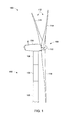
- FIG. 1 is a side elevation view of an exemplary wind turbine 100.
- wind turbine 100 is a horizontal axis wind turbine.
- wind turbine 100 may be a vertical axis wind turbine.
- Wind turbine 100 includes a tower 102 erected from a foundation (not shown), a nacelle 104 mounted on tower 102, and a rotor 108 rotatably coupled to nacelle 104.
- Tower 102 includes a plurality of tower sections 106 that are stacked atop of one another and are coupled together using a suitable coupler or fastener, such as a plurality of bolts, for example.
- rotor 108 includes a rotatable hub 110 and a plurality of rotor blades 112 coupled to and extending outwardly from hub 110.
- rotor blades 112 include a first rotor blade 114, a second rotor blade 116, and a third rotor blade 118.
- rotor 108 may include any suitable number of rotor blades 112.
- rotor blades 112 are generally equidistantly spaced about hub 110 to facilitate enabling kinetic energy of the wind to be converted into rotational energy and, subsequently, into electrical energy.
- rotor blades 112 may be spaced any suitable distance from one another about hub 110.
- FIG. 2 is a side elevation view of one known wind turbine 200 including tower 202, nacelle 204 and rotor 208 having blades 212.
- the tower 202 typically includes multiple sections 206 which may be cylindrical in cross-section or have a tapered cross-section with the largest diameter near the bottom and the smallest diameter at the top.
- the rotor 208 has a radius 209, which is approximately equal to a length of one of the blades 212 plus half the diameter of the hub 110.
- Blade 212 will flex inward when under load, as indicated by the blade 212 shown in phantom.
- the tip 213 of the blade 212 shown in its lowest position during rotation, has a static clearance distance indicated by 214.
- the static clearance is defined as the distance between the tower's outer diameter to the blade tip, at lowest position, under no-load conditions.
- the blade tip 213 will move closer to the tower and have a reduced clearance as indicated by 215.
- the blades 212 should be designed with a stiffness that prevents them from hitting tower 202 during operational conditions.
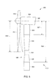
- FIG. 3 illustrates a side elevation view of a wind turbine 300 including tower 302, nacelle 304 and rotor 308 having blades 312, according to one aspect of the present invention.
- the tower 302 typically may include multiple sections 306 which may be cylindrical or have a tapered shape with a larger diameter near the bottom and a smaller diameter near the top. Tower sections 306 may also be frusto-conical in shape.
- the rotor 308 has a radius 309, which is approximately equal to a length of one of the blades 312 plus half the diameter of the hub 310.
- the tower 302 includes a reduced diameter section 320 located near the radius 309 of the rotor 308.
- the tip 313 of one of the blades 312 is shown in its lowest position during rotation.
- the position of the reduced diameter section 320, in tower 302, can be about 100% of the radius 309 of rotor 308 below the rotor's centerline 307, or about equal to a length of one of the blades 312 plus half the height 310 of the hub.
- the narrowest part of reduced diameter section 320 can be positioned about 60 meters below the rotor's centerline 307.
- the entire length of section 320 may extend about 50% of the rotor's radius below centerline 307 to about 150% of the rotor's radius below centerline 307.
- the reduced diameter section 320 may be comprised of one monolithic section, or it may be comprised of multiple sections.
- section 320 could be obtained by stacking multiple "cans" (e.g., cylindrical, frusto-conical or tapered tower sections) having various diameters on top of one another. In general, it is preferred to have the smallest diameter section of reduced diameter section 320 located near the blade tip's lowest vertical position.
- the outer profile of the reduced diameter section 320 may have any suitable shape, including but not limited to, hyperbolic, concave, hour-glass, tapered, conical, frusto-conical, as well as variations on these shapes.
- the reduced diameter section is shown to have a generally hour-glass shaped profile.
- the thickness of the tower wall may be increased in all or portions of the reduced diameter section 320, in order to counteract the reduction in either strength or stiffness due to the reduction in tower diameter.
- FIG. 4 illustrates a side elevation view of a wind turbine 400 including tower 402, nacelle 304 and rotor 308 having blades 312, according to one aspect of the present invention.
- the tower 402 typically may include multiple sections 406 which may be cylindrical or frusto-conical in shape or have sections 407 that are tapered with a larger diameter near the bottom and a smaller diameter near the top.
- the reduced diameter section 420 can be comprised on one or more tapered sections 422, 423, and zero or more cylindrical sections 424.
- Section 422 can be tapered to have a smaller diameter with increasing elevation, while section 423 can be tapered to have an increasing diameter with increasing elevation.
- sections 422 and 423 may have a conical or frusto-conical (as shown in FIG. 4 ) shape.
- Section 424 may be cylindrical in shape and may comprise one or more "cans" stacked upon each other. In some applications, it may be desired to omit section 424 and use only sections 422 and 423 instead.
- the thickness of the tower wall may be increased in all or portions of the reduced diameter section 420, in order to counteract the reduction in either strength or stiffness due to the reduction in tower diameter.
- FIG. 5 illustrates a side elevation view of a wind turbine 500 including tower 502, nacelle 304 and rotor 308 having blades 312, according to one aspect of the present invention.
- the tower 502 may include multiple sections 503 which may be cylindrical or frusto-conical in shape.
- the sections 503 may have a tapered shape with a larger diameter near the bottom and a smaller diameter near the top, or a larger diameter near the top and a smaller diameter near the bottom.
- the reduced diameter section 520 can be comprised of one or more tapered sections 522, 523, and zero or more cylindrical sections 524.
- Section 522 can be tapered to have a smaller diameter with increasing elevation
- section 523 can be tapered to have an increasing diameter with increasing elevation.
- sections 522 and 523 may have a conical or frusto-conical shape.
- Section 524 may be cylindrical in shape and each section 522, 523 and 524 may comprise one or more "cans" stacked upon each other. In some applications, it may be desired to omit section 524 and use only sections 522 and 523 instead.
- the thickness of the tower wall may be increased in all or portions of the reduced diameter section 520, in order to counteract the reduction in either strength or stiffness due to the reduction in tower diameter.
- the reduced diameter section 520 can be located in any suitable position in tower 502.
- the top of section 523 can be located a distance 527 of about 50% of the rotor's radius 309 from centerline 307.
- the narrowest part, or waist portion 524, of the reduced diameter section is preferably located about 100% of the rotor's radius 309 from centerline 307.
- the bottom of section 522 can be located a distance 528 of about 150% of the rotor's radius 309 from centerline 307. This is but one example, and the top, middle and bottom portions of reduced diameter section 520 can be located at any appropriate position in tower 502, as desired in the specific application.
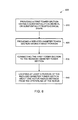
- FIG. 6 is a flow chart of a method 600 for fabricating or making a wind turbine tower as described herein.
- the method includes providing 610 a first tower section having a substantially cylindrical or substantially frusto-conical shape.
- the first tower section has at least a first diameter.
- the method also includes providing 620 a reduced diameter tower section having a waist portion with at least one second diameter, the second diameter being smaller than the first diameter, and connecting 630 the first tower section to the reduced diameter tower section.
- the providing step 620 can include providing at least a portion of the reduced diameter tower section having a shape chosen from one or more of, generally hourglass, generally hyperbolic, generally concave, generally tapered, and/or generally frusto-conical.
- the providing step 620 may also include providing one or more transition sections, in the reduced diameter tower section, the transition sections having a diameter that transitions from about the first diameter to about the second diameter.
- An additional step can include providing a first transition section having a diameter that transitions from about the first diameter to about the second diameter, where the first transition section is located below and adjacent the waist portion, and providing a second transition section having a diameter that transitions from about the second diameter to about a third diameter, the third diameter being greater than the second diameter and equal to or less than the first diameter, where the second transition section is located above and adjacent to the waist portion.
- Another step includes locating 640 at least a portion of the reduced diameter tower section about one radius distance from the centerline of the rotor.
- the locating step 640 may also include locating the reduced diameter tower section between about 50% of the radius distance to about 150% of the radius distance from the centerline of the rotor.
- the location of the reduced diameter tower section could also span longer or shorter portions of the tower, as desired by the specific application.
- Exemplary embodiments of a wind turbine, wind turbine tower and methods for fabricating or making the same are described above in detail.
- the methods and devices described herein are not limited to the specific embodiments described herein, but rather, components of the devices and/or steps of the methods may be utilized independently and separately from other components and/or steps described herein.
- the devices and methods described herein may have other applications not limited to practice with wind turbines, as described herein. Rather, the methods and devices described herein can be implemented and utilized in connection with various other industries.
Landscapes
- Engineering & Computer Science (AREA)
- Life Sciences & Earth Sciences (AREA)
- Sustainable Development (AREA)
- Sustainable Energy (AREA)
- Chemical & Material Sciences (AREA)
- Combustion & Propulsion (AREA)
- Mechanical Engineering (AREA)
- General Engineering & Computer Science (AREA)
- Wind Motors (AREA)
Applications Claiming Priority (1)
| Application Number | Priority Date | Filing Date | Title |
|---|---|---|---|
| US12/751,102 US7997876B2 (en) | 2010-03-31 | 2010-03-31 | Wind turbine, tower and method for fabricating the same |
Publications (3)
| Publication Number | Publication Date |
|---|---|
| EP2372144A2 true EP2372144A2 (fr) | 2011-10-05 |
| EP2372144A3 EP2372144A3 (fr) | 2014-10-15 |
| EP2372144B1 EP2372144B1 (fr) | 2016-07-27 |
Family
ID=43824232
Family Applications (1)
| Application Number | Title | Priority Date | Filing Date |
|---|---|---|---|
| EP11159673.0A Not-in-force EP2372144B1 (fr) | 2010-03-31 | 2011-03-24 | Eolienne, tour et un procédé de fabrication de la même |
Country Status (5)
| Country | Link |
|---|---|
| US (1) | US7997876B2 (fr) |
| EP (1) | EP2372144B1 (fr) |
| CN (1) | CN102207059B (fr) |
| AU (1) | AU2011201271B2 (fr) |
| CA (1) | CA2734360A1 (fr) |
Cited By (1)
| Publication number | Priority date | Publication date | Assignee | Title |
|---|---|---|---|---|
| CN102943740A (zh) * | 2012-10-25 | 2013-02-27 | 吕婕 | 长柄宽叶翼风车风桨桨叶 |
Families Citing this family (12)
| Publication number | Priority date | Publication date | Assignee | Title |
|---|---|---|---|---|
| US8253268B1 (en) | 2009-10-15 | 2012-08-28 | Airgenesis, LLC | Wind power generation system |
| WO2011046632A1 (fr) | 2009-10-15 | 2011-04-21 | Smith Danny J | Système de production d'énergie éolienne |
| US8448527B2 (en) * | 2011-10-14 | 2013-05-28 | General Electric Company | Methods for using site specific wind conditions to determine when to install a tip feature on a wind turbine rotor blade |
| US9140029B2 (en) * | 2012-01-20 | 2015-09-22 | Illinois Tool Works Inc. | Tower erecting system |
| EP2834518B1 (fr) | 2012-04-06 | 2019-03-27 | Airgenesis, LLC | Système de production d'énergie éolienne à vitesse de rotation régulée |
| CN103375354B (zh) * | 2012-04-27 | 2016-12-14 | 周登荣 | 风塔风力发电底部钢架 |
| DK2703640T3 (en) | 2012-08-28 | 2018-12-10 | Nordex Energy Gmbh | PROCEDURE FOR THE CONSTRUCTION OF A TOWER FOR A WIND ENERGY INSTALLATION AND TOWER FOR A WIND ENERGY INSTALLATION |
| WO2014130067A1 (fr) | 2013-02-25 | 2014-08-28 | Airgenesis, LLC | Commande de coupleur variable |
| EP2846041B1 (fr) * | 2013-09-06 | 2018-01-17 | youWINenergy GmbH | Installation d'éolienne rénovée |
| US9617979B2 (en) | 2013-10-30 | 2017-04-11 | Airgenesis, LLC | Motor assisted power generation system |
| ES2705034T3 (es) | 2014-02-17 | 2019-03-21 | Nordex Energy Gmbh | Instalación de energía eólica con una torre |
| CN109707571B (zh) * | 2018-12-07 | 2020-09-25 | 山东中车风电有限公司 | 基于频率控制的风电机组双曲线型塔筒设计方法及塔筒 |
Family Cites Families (17)
| Publication number | Priority date | Publication date | Assignee | Title |
|---|---|---|---|---|
| US1674169A (en) * | 1923-07-28 | 1928-06-19 | Inst Voor Aeroen Hydro Dynamie | Arrangement for exchanging energy between a current and a body therein |
| US3922827A (en) | 1973-06-01 | 1975-12-02 | Joel H Rosenblatt | Hyperbolic tower structure |
| US4261147A (en) | 1978-09-21 | 1981-04-14 | Agsten Carl F | Hyperbolic natural draft cooling tower construction |
| US4715782A (en) * | 1985-12-24 | 1987-12-29 | Fayette Manufacturing Corp. | Hydraulic control device for wind turbine |
| DE29612720U1 (de) | 1996-07-23 | 1996-10-02 | aerodyn GmbH, 24768 Rendsburg | Windkraftanlage |
| US6467233B1 (en) * | 2000-11-09 | 2002-10-22 | Beaird Industries, Inc | Wind tower |
| US6470645B1 (en) * | 2000-11-09 | 2002-10-29 | Beaird Industries, Inc. | Method for making and erecting a wind tower |
| DE10339438C5 (de) * | 2003-08-25 | 2011-09-15 | Repower Systems Ag | Turm für eine Windenergieanlage |
| JP4468751B2 (ja) * | 2004-06-30 | 2010-05-26 | 富士重工業株式会社 | 水平軸風車およびその待機方法 |
| ES1058539Y (es) * | 2004-10-11 | 2005-04-01 | Inneo21 S L | Estructura perfeccionada de torre modular para turbinas eolicas y otras aplicaciones. |
| DE102006027224B3 (de) * | 2006-06-12 | 2008-01-03 | Repower Systems Ag | Windenergieanlage mit einer autarken Energieversorgung für eine Blattverstelleinrichtung |
| DE102007020483A1 (de) * | 2007-04-27 | 2008-10-30 | Joachim Falkenhagen | Offshore-Tragstruktur mit konischem Übergangsstück und Zugang in Nähe der Wasserlinie |
| US8047804B2 (en) * | 2007-12-27 | 2011-11-01 | General Electric Company | Wind tower and method of assembling the same |
| US20090107567A1 (en) * | 2007-10-26 | 2009-04-30 | Crary Peter B | Combination water tower and electrical wind turbine generator |
| US20090167023A1 (en) * | 2007-12-27 | 2009-07-02 | Jacob Johannes Nies | Forward leaning tower top section |
| US20090249707A1 (en) | 2008-04-08 | 2009-10-08 | Curme Oliver D | Supporting a wind-driven electric generator |
| ES2386519T3 (es) * | 2008-11-27 | 2012-08-22 | Vestas Wind Systems A/S | Torre para una turbina eólica y método para montar la torre |
-
2010
- 2010-03-31 US US12/751,102 patent/US7997876B2/en not_active Expired - Fee Related
-
2011
- 2011-03-17 CA CA2734360A patent/CA2734360A1/fr not_active Abandoned
- 2011-03-22 AU AU2011201271A patent/AU2011201271B2/en not_active Expired - Fee Related
- 2011-03-24 EP EP11159673.0A patent/EP2372144B1/fr not_active Not-in-force
- 2011-03-31 CN CN201110093470.3A patent/CN102207059B/zh not_active Expired - Fee Related
Non-Patent Citations (1)
| Title |
|---|
| None |
Cited By (1)
| Publication number | Priority date | Publication date | Assignee | Title |
|---|---|---|---|---|
| CN102943740A (zh) * | 2012-10-25 | 2013-02-27 | 吕婕 | 长柄宽叶翼风车风桨桨叶 |
Also Published As
| Publication number | Publication date |
|---|---|
| EP2372144A3 (fr) | 2014-10-15 |
| EP2372144B1 (fr) | 2016-07-27 |
| CA2734360A1 (fr) | 2011-09-30 |
| US20110135493A1 (en) | 2011-06-09 |
| CN102207059B (zh) | 2014-10-15 |
| AU2011201271A1 (en) | 2011-10-20 |
| CN102207059A (zh) | 2011-10-05 |
| AU2011201271B2 (en) | 2016-06-23 |
| US7997876B2 (en) | 2011-08-16 |
Similar Documents
| Publication | Publication Date | Title |
|---|---|---|
| EP2372144B1 (fr) | Eolienne, tour et un procédé de fabrication de la même | |
| KR101411057B1 (ko) | 풍력 터빈 로터 | |
| US8066490B2 (en) | Wind turbine rotor blade | |
| KR101143784B1 (ko) | 풍차용 타워 및 풍력 발전 장치 | |
| EP2375057B1 (fr) | Installation d'éoliennes | |
| US8714928B2 (en) | Rotor assembly for a wind turbine and method of assembling the same | |
| EP2728170B1 (fr) | Pale d'éolienne avec un décalage côté aspiration | |
| US20130183164A1 (en) | Vertical axis wind turbine having one or more modular blades | |
| US20130193691A1 (en) | Improvements to a wind turbine assembly | |
| EP2453081A2 (fr) | Assemblage de renfort à utiliser avec le pylône de support d'une éolienne | |
| US20090317256A1 (en) | Rotor hub of a wind energy plant | |
| EP2933476A1 (fr) | Palier de pas renforcé d'une éolienne | |
| GB2468881A (en) | Vertical axis wind turbine | |
| CN107076121B (zh) | 垂直轴风力机转子的塔架结构 | |
| EP1729007A2 (fr) | Tour pour une éolienne | |
| EP4363713B1 (fr) | Pièce de transition pour tour éolienne hybride et procédé d'assemblage de cette dernière | |
| EP3635249B1 (fr) | Montage de tour pour une turbine a vent et méthode de réglage d'une telle tour | |
| EP3312413A1 (fr) | Dispositif de génération d'énergie éolienne | |
| EP3267032B1 (fr) | Agencement de palier de pales pour une éolienne | |
| OA18231A (en) | Tower structure for vertical-axis wind turbine rotor. |
Legal Events
| Date | Code | Title | Description |
|---|---|---|---|
| PUAI | Public reference made under article 153(3) epc to a published international application that has entered the european phase |
Free format text: ORIGINAL CODE: 0009012 |
|
| AK | Designated contracting states |
Kind code of ref document: A2 Designated state(s): AL AT BE BG CH CY CZ DE DK EE ES FI FR GB GR HR HU IE IS IT LI LT LU LV MC MK MT NL NO PL PT RO RS SE SI SK SM TR |
|
| AX | Request for extension of the european patent |
Extension state: BA ME |
|
| PUAL | Search report despatched |
Free format text: ORIGINAL CODE: 0009013 |
|
| AK | Designated contracting states |
Kind code of ref document: A3 Designated state(s): AL AT BE BG CH CY CZ DE DK EE ES FI FR GB GR HR HU IE IS IT LI LT LU LV MC MK MT NL NO PL PT RO RS SE SI SK SM TR |
|
| AX | Request for extension of the european patent |
Extension state: BA ME |
|
| RIC1 | Information provided on ipc code assigned before grant |
Ipc: F03D 11/04 20060101ALI20140905BHEP Ipc: F03D 1/00 20060101AFI20140905BHEP |
|
| 17P | Request for examination filed |
Effective date: 20150415 |
|
| RBV | Designated contracting states (corrected) |
Designated state(s): AL AT BE BG CH CY CZ DE DK EE ES FI FR GB GR HR HU IE IS IT LI LT LU LV MC MK MT NL NO PL PT RO RS SE SI SK SM TR |
|
| 17Q | First examination report despatched |
Effective date: 20150821 |
|
| REG | Reference to a national code |
Ref country code: DE Ref legal event code: R079 Ref document number: 602011028502 Country of ref document: DE Free format text: PREVIOUS MAIN CLASS: F03D0001000000 Ipc: F03D0013200000 |
|
| GRAP | Despatch of communication of intention to grant a patent |
Free format text: ORIGINAL CODE: EPIDOSNIGR1 |
|
| RIC1 | Information provided on ipc code assigned before grant |
Ipc: F03D 13/20 20160101AFI20160205BHEP |
|
| INTG | Intention to grant announced |
Effective date: 20160222 |
|
| GRAS | Grant fee paid |
Free format text: ORIGINAL CODE: EPIDOSNIGR3 |
|
| GRAA | (expected) grant |
Free format text: ORIGINAL CODE: 0009210 |
|
| AK | Designated contracting states |
Kind code of ref document: B1 Designated state(s): AL AT BE BG CH CY CZ DE DK EE ES FI FR GB GR HR HU IE IS IT LI LT LU LV MC MK MT NL NO PL PT RO RS SE SI SK SM TR |
|
| REG | Reference to a national code |
Ref country code: GB Ref legal event code: FG4D |
|
| REG | Reference to a national code |
Ref country code: CH Ref legal event code: EP |
|
| REG | Reference to a national code |
Ref country code: AT Ref legal event code: REF Ref document number: 816040 Country of ref document: AT Kind code of ref document: T Effective date: 20160815 |
|
| REG | Reference to a national code |
Ref country code: IE Ref legal event code: FG4D |
|
| REG | Reference to a national code |
Ref country code: DE Ref legal event code: R096 Ref document number: 602011028502 Country of ref document: DE |
|
| REG | Reference to a national code |
Ref country code: LT Ref legal event code: MG4D |
|
| REG | Reference to a national code |
Ref country code: NL Ref legal event code: MP Effective date: 20160727 |
|
| REG | Reference to a national code |
Ref country code: AT Ref legal event code: MK05 Ref document number: 816040 Country of ref document: AT Kind code of ref document: T Effective date: 20160727 |
|
| PG25 | Lapsed in a contracting state [announced via postgrant information from national office to epo] |
Ref country code: IT Free format text: LAPSE BECAUSE OF FAILURE TO SUBMIT A TRANSLATION OF THE DESCRIPTION OR TO PAY THE FEE WITHIN THE PRESCRIBED TIME-LIMIT Effective date: 20160727 Ref country code: RS Free format text: LAPSE BECAUSE OF FAILURE TO SUBMIT A TRANSLATION OF THE DESCRIPTION OR TO PAY THE FEE WITHIN THE PRESCRIBED TIME-LIMIT Effective date: 20160727 Ref country code: LT Free format text: LAPSE BECAUSE OF FAILURE TO SUBMIT A TRANSLATION OF THE DESCRIPTION OR TO PAY THE FEE WITHIN THE PRESCRIBED TIME-LIMIT Effective date: 20160727 Ref country code: NL Free format text: LAPSE BECAUSE OF FAILURE TO SUBMIT A TRANSLATION OF THE DESCRIPTION OR TO PAY THE FEE WITHIN THE PRESCRIBED TIME-LIMIT Effective date: 20160727 Ref country code: NO Free format text: LAPSE BECAUSE OF FAILURE TO SUBMIT A TRANSLATION OF THE DESCRIPTION OR TO PAY THE FEE WITHIN THE PRESCRIBED TIME-LIMIT Effective date: 20161027 Ref country code: HR Free format text: LAPSE BECAUSE OF FAILURE TO SUBMIT A TRANSLATION OF THE DESCRIPTION OR TO PAY THE FEE WITHIN THE PRESCRIBED TIME-LIMIT Effective date: 20160727 Ref country code: FI Free format text: LAPSE BECAUSE OF FAILURE TO SUBMIT A TRANSLATION OF THE DESCRIPTION OR TO PAY THE FEE WITHIN THE PRESCRIBED TIME-LIMIT Effective date: 20160727 Ref country code: IS Free format text: LAPSE BECAUSE OF FAILURE TO SUBMIT A TRANSLATION OF THE DESCRIPTION OR TO PAY THE FEE WITHIN THE PRESCRIBED TIME-LIMIT Effective date: 20161127 |
|
| PG25 | Lapsed in a contracting state [announced via postgrant information from national office to epo] |
Ref country code: GR Free format text: LAPSE BECAUSE OF FAILURE TO SUBMIT A TRANSLATION OF THE DESCRIPTION OR TO PAY THE FEE WITHIN THE PRESCRIBED TIME-LIMIT Effective date: 20161028 Ref country code: PT Free format text: LAPSE BECAUSE OF FAILURE TO SUBMIT A TRANSLATION OF THE DESCRIPTION OR TO PAY THE FEE WITHIN THE PRESCRIBED TIME-LIMIT Effective date: 20161128 Ref country code: ES Free format text: LAPSE BECAUSE OF FAILURE TO SUBMIT A TRANSLATION OF THE DESCRIPTION OR TO PAY THE FEE WITHIN THE PRESCRIBED TIME-LIMIT Effective date: 20160727 Ref country code: SE Free format text: LAPSE BECAUSE OF FAILURE TO SUBMIT A TRANSLATION OF THE DESCRIPTION OR TO PAY THE FEE WITHIN THE PRESCRIBED TIME-LIMIT Effective date: 20160727 Ref country code: PL Free format text: LAPSE BECAUSE OF FAILURE TO SUBMIT A TRANSLATION OF THE DESCRIPTION OR TO PAY THE FEE WITHIN THE PRESCRIBED TIME-LIMIT Effective date: 20160727 Ref country code: BE Free format text: LAPSE BECAUSE OF FAILURE TO SUBMIT A TRANSLATION OF THE DESCRIPTION OR TO PAY THE FEE WITHIN THE PRESCRIBED TIME-LIMIT Effective date: 20160727 Ref country code: AT Free format text: LAPSE BECAUSE OF FAILURE TO SUBMIT A TRANSLATION OF THE DESCRIPTION OR TO PAY THE FEE WITHIN THE PRESCRIBED TIME-LIMIT Effective date: 20160727 Ref country code: LV Free format text: LAPSE BECAUSE OF FAILURE TO SUBMIT A TRANSLATION OF THE DESCRIPTION OR TO PAY THE FEE WITHIN THE PRESCRIBED TIME-LIMIT Effective date: 20160727 |
|
| PG25 | Lapsed in a contracting state [announced via postgrant information from national office to epo] |
Ref country code: EE Free format text: LAPSE BECAUSE OF FAILURE TO SUBMIT A TRANSLATION OF THE DESCRIPTION OR TO PAY THE FEE WITHIN THE PRESCRIBED TIME-LIMIT Effective date: 20160727 Ref country code: RO Free format text: LAPSE BECAUSE OF FAILURE TO SUBMIT A TRANSLATION OF THE DESCRIPTION OR TO PAY THE FEE WITHIN THE PRESCRIBED TIME-LIMIT Effective date: 20160727 |
|
| REG | Reference to a national code |
Ref country code: DE Ref legal event code: R097 Ref document number: 602011028502 Country of ref document: DE |
|
| PG25 | Lapsed in a contracting state [announced via postgrant information from national office to epo] |
Ref country code: SM Free format text: LAPSE BECAUSE OF FAILURE TO SUBMIT A TRANSLATION OF THE DESCRIPTION OR TO PAY THE FEE WITHIN THE PRESCRIBED TIME-LIMIT Effective date: 20160727 Ref country code: SK Free format text: LAPSE BECAUSE OF FAILURE TO SUBMIT A TRANSLATION OF THE DESCRIPTION OR TO PAY THE FEE WITHIN THE PRESCRIBED TIME-LIMIT Effective date: 20160727 Ref country code: CZ Free format text: LAPSE BECAUSE OF FAILURE TO SUBMIT A TRANSLATION OF THE DESCRIPTION OR TO PAY THE FEE WITHIN THE PRESCRIBED TIME-LIMIT Effective date: 20160727 Ref country code: BG Free format text: LAPSE BECAUSE OF FAILURE TO SUBMIT A TRANSLATION OF THE DESCRIPTION OR TO PAY THE FEE WITHIN THE PRESCRIBED TIME-LIMIT Effective date: 20161027 Ref country code: DK Free format text: LAPSE BECAUSE OF FAILURE TO SUBMIT A TRANSLATION OF THE DESCRIPTION OR TO PAY THE FEE WITHIN THE PRESCRIBED TIME-LIMIT Effective date: 20160727 |
|
| PLBE | No opposition filed within time limit |
Free format text: ORIGINAL CODE: 0009261 |
|
| STAA | Information on the status of an ep patent application or granted ep patent |
Free format text: STATUS: NO OPPOSITION FILED WITHIN TIME LIMIT |
|
| 26N | No opposition filed |
Effective date: 20170502 |
|
| PG25 | Lapsed in a contracting state [announced via postgrant information from national office to epo] |
Ref country code: SI Free format text: LAPSE BECAUSE OF FAILURE TO SUBMIT A TRANSLATION OF THE DESCRIPTION OR TO PAY THE FEE WITHIN THE PRESCRIBED TIME-LIMIT Effective date: 20160727 |
|
| REG | Reference to a national code |
Ref country code: DE Ref legal event code: R119 Ref document number: 602011028502 Country of ref document: DE |
|
| REG | Reference to a national code |
Ref country code: CH Ref legal event code: PL |
|
| GBPC | Gb: european patent ceased through non-payment of renewal fee |
Effective date: 20170324 |
|
| PG25 | Lapsed in a contracting state [announced via postgrant information from national office to epo] |
Ref country code: MC Free format text: LAPSE BECAUSE OF FAILURE TO SUBMIT A TRANSLATION OF THE DESCRIPTION OR TO PAY THE FEE WITHIN THE PRESCRIBED TIME-LIMIT Effective date: 20160727 |
|
| REG | Reference to a national code |
Ref country code: IE Ref legal event code: MM4A |
|
| REG | Reference to a national code |
Ref country code: FR Ref legal event code: ST Effective date: 20171130 |
|
| PG25 | Lapsed in a contracting state [announced via postgrant information from national office to epo] |
Ref country code: LU Free format text: LAPSE BECAUSE OF NON-PAYMENT OF DUE FEES Effective date: 20170324 Ref country code: DE Free format text: LAPSE BECAUSE OF NON-PAYMENT OF DUE FEES Effective date: 20171003 Ref country code: FR Free format text: LAPSE BECAUSE OF NON-PAYMENT OF DUE FEES Effective date: 20170331 |
|
| PG25 | Lapsed in a contracting state [announced via postgrant information from national office to epo] |
Ref country code: IE Free format text: LAPSE BECAUSE OF NON-PAYMENT OF DUE FEES Effective date: 20170324 Ref country code: GB Free format text: LAPSE BECAUSE OF NON-PAYMENT OF DUE FEES Effective date: 20170324 Ref country code: CH Free format text: LAPSE BECAUSE OF NON-PAYMENT OF DUE FEES Effective date: 20170331 Ref country code: LI Free format text: LAPSE BECAUSE OF NON-PAYMENT OF DUE FEES Effective date: 20170331 |
|
| PG25 | Lapsed in a contracting state [announced via postgrant information from national office to epo] |
Ref country code: MT Free format text: LAPSE BECAUSE OF NON-PAYMENT OF DUE FEES Effective date: 20170324 |
|
| PG25 | Lapsed in a contracting state [announced via postgrant information from national office to epo] |
Ref country code: AL Free format text: LAPSE BECAUSE OF FAILURE TO SUBMIT A TRANSLATION OF THE DESCRIPTION OR TO PAY THE FEE WITHIN THE PRESCRIBED TIME-LIMIT Effective date: 20160727 |
|
| PG25 | Lapsed in a contracting state [announced via postgrant information from national office to epo] |
Ref country code: HU Free format text: LAPSE BECAUSE OF FAILURE TO SUBMIT A TRANSLATION OF THE DESCRIPTION OR TO PAY THE FEE WITHIN THE PRESCRIBED TIME-LIMIT; INVALID AB INITIO Effective date: 20110324 |
|
| PG25 | Lapsed in a contracting state [announced via postgrant information from national office to epo] |
Ref country code: CY Free format text: LAPSE BECAUSE OF NON-PAYMENT OF DUE FEES Effective date: 20160727 |
|
| PG25 | Lapsed in a contracting state [announced via postgrant information from national office to epo] |
Ref country code: MK Free format text: LAPSE BECAUSE OF FAILURE TO SUBMIT A TRANSLATION OF THE DESCRIPTION OR TO PAY THE FEE WITHIN THE PRESCRIBED TIME-LIMIT Effective date: 20160727 |
|
| PG25 | Lapsed in a contracting state [announced via postgrant information from national office to epo] |
Ref country code: TR Free format text: LAPSE BECAUSE OF FAILURE TO SUBMIT A TRANSLATION OF THE DESCRIPTION OR TO PAY THE FEE WITHIN THE PRESCRIBED TIME-LIMIT Effective date: 20160727 |