EP2372148A1 - Dispositif d'entraînement pour une éolienne - Google Patents
Dispositif d'entraînement pour une éolienne Download PDFInfo
- Publication number
- EP2372148A1 EP2372148A1 EP10003558A EP10003558A EP2372148A1 EP 2372148 A1 EP2372148 A1 EP 2372148A1 EP 10003558 A EP10003558 A EP 10003558A EP 10003558 A EP10003558 A EP 10003558A EP 2372148 A1 EP2372148 A1 EP 2372148A1
- Authority
- EP
- European Patent Office
- Prior art keywords
- drive device
- pinion
- central
- carrier element
- shaft
- Prior art date
- Legal status (The legal status is an assumption and is not a legal conclusion. Google has not performed a legal analysis and makes no representation as to the accuracy of the status listed.)
- Granted
Links
- 230000005540 biological transmission Effects 0.000 claims description 6
- 230000008878 coupling Effects 0.000 claims 1
- 238000010168 coupling process Methods 0.000 claims 1
- 238000005859 coupling reaction Methods 0.000 claims 1
- 238000012423 maintenance Methods 0.000 description 5
- 230000000712 assembly Effects 0.000 description 2
- 238000000429 assembly Methods 0.000 description 2
- 238000011161 development Methods 0.000 description 2
- 230000018109 developmental process Effects 0.000 description 2
- 230000001419 dependent effect Effects 0.000 description 1
Images



Classifications
-
- F—MECHANICAL ENGINEERING; LIGHTING; HEATING; WEAPONS; BLASTING
- F03—MACHINES OR ENGINES FOR LIQUIDS; WIND, SPRING, OR WEIGHT MOTORS; PRODUCING MECHANICAL POWER OR A REACTIVE PROPULSIVE THRUST, NOT OTHERWISE PROVIDED FOR
- F03D—WIND MOTORS
- F03D15/00—Transmission of mechanical power
-
- F—MECHANICAL ENGINEERING; LIGHTING; HEATING; WEAPONS; BLASTING
- F03—MACHINES OR ENGINES FOR LIQUIDS; WIND, SPRING, OR WEIGHT MOTORS; PRODUCING MECHANICAL POWER OR A REACTIVE PROPULSIVE THRUST, NOT OTHERWISE PROVIDED FOR
- F03D—WIND MOTORS
- F03D15/00—Transmission of mechanical power
- F03D15/10—Transmission of mechanical power using gearing not limited to rotary motion, e.g. with oscillating or reciprocating members
-
- F—MECHANICAL ENGINEERING; LIGHTING; HEATING; WEAPONS; BLASTING
- F03—MACHINES OR ENGINES FOR LIQUIDS; WIND, SPRING, OR WEIGHT MOTORS; PRODUCING MECHANICAL POWER OR A REACTIVE PROPULSIVE THRUST, NOT OTHERWISE PROVIDED FOR
- F03D—WIND MOTORS
- F03D80/00—Details, components or accessories not provided for in groups F03D1/00 - F03D17/00
- F03D80/70—Bearing or lubricating arrangements
-
- F—MECHANICAL ENGINEERING; LIGHTING; HEATING; WEAPONS; BLASTING
- F05—INDEXING SCHEMES RELATING TO ENGINES OR PUMPS IN VARIOUS SUBCLASSES OF CLASSES F01-F04
- F05B—INDEXING SCHEME RELATING TO WIND, SPRING, WEIGHT, INERTIA OR LIKE MOTORS, TO MACHINES OR ENGINES FOR LIQUIDS COVERED BY SUBCLASSES F03B, F03D AND F03G
- F05B2250/00—Geometry
- F05B2250/10—Geometry two-dimensional
- F05B2250/11—Geometry two-dimensional triangular
-
- F—MECHANICAL ENGINEERING; LIGHTING; HEATING; WEAPONS; BLASTING
- F05—INDEXING SCHEMES RELATING TO ENGINES OR PUMPS IN VARIOUS SUBCLASSES OF CLASSES F01-F04
- F05B—INDEXING SCHEME RELATING TO WIND, SPRING, WEIGHT, INERTIA OR LIKE MOTORS, TO MACHINES OR ENGINES FOR LIQUIDS COVERED BY SUBCLASSES F03B, F03D AND F03G
- F05B2260/00—Function
- F05B2260/40—Transmission of power
- F05B2260/403—Transmission of power through the shape of the drive components
- F05B2260/4031—Transmission of power through the shape of the drive components as in toothed gearing
- F05B2260/40311—Transmission of power through the shape of the drive components as in toothed gearing of the epicyclic, planetary or differential type
-
- Y—GENERAL TAGGING OF NEW TECHNOLOGICAL DEVELOPMENTS; GENERAL TAGGING OF CROSS-SECTIONAL TECHNOLOGIES SPANNING OVER SEVERAL SECTIONS OF THE IPC; TECHNICAL SUBJECTS COVERED BY FORMER USPC CROSS-REFERENCE ART COLLECTIONS [XRACs] AND DIGESTS
- Y02—TECHNOLOGIES OR APPLICATIONS FOR MITIGATION OR ADAPTATION AGAINST CLIMATE CHANGE
- Y02E—REDUCTION OF GREENHOUSE GAS [GHG] EMISSIONS, RELATED TO ENERGY GENERATION, TRANSMISSION OR DISTRIBUTION
- Y02E10/00—Energy generation through renewable energy sources
- Y02E10/70—Wind energy
- Y02E10/72—Wind turbines with rotation axis in wind direction
Definitions
- EP 1 279 867 B1 There is described a multi-stage transmission with an internal power split comprising an externally toothed large gear connected to an input shaft.
- the large gear is surrounded by a plurality of pinion shafts whose pinion gear mesh with the large gear.
- the pinion shafts each carry a gear wheel.
- Two gears each form a gear pair and are alternately arranged in front of and behind the large gear.
- the gears are provided with helical teeth of different pitch direction and are engaged with a common, double helical, axially freely mounted pinion shaft.
- the large gear is surrounded by a total of eight pinion shafts, the gears with four in each case a gear pair common, double helical, axially freely mounted pinion shafts are engaged and form with these a first stage of the power distribution.
- the four first-order power splitting pinion shafts communicate with four second-order power splitting pinion shafts.
- the four pinion shafts of the second stage power distribution in turn each carry a gear, two gears form a pair of gears.
- the gears of a gear pair are in engagement with two freely spaced pinion shafts, each having a gear pair.
- EP 1 619 386 B1 is a multistage power split wind turbine gear for a wind turbine higher power known, which is opposite to the in EP 1 279 867 B1 in particular characterized differs in that instead of a power split to two or more parallel output shafts, a power split takes place on only one generator-side shaft. All pinion shafts are simply helically toothed and mounted over at least two spaced pure radial bearings and at least one pure thrust bearing. This already requires a high number of parts for the storage of the pinion shafts.
- the present invention has for its object to provide a drive device for a wind turbine, which allows increased reliability and improved serviceability.
- the pinion shafts are each mounted by means arranged at vertices of the carrier elements pinion shaft bearings.
- the pinion shaft bearings are fixed by bearing seat members to the support members.
- At least one support element is in addition to the storage of a connectable to a rotor hub connecting shaft configured, which is surrounded by this support member and whose axis extends through the center of the support member.
- a first gear stage of the drive device according to the invention has an externally toothed central wheel.
- the central wheel is mounted on the connecting shaft designed, for example, as a hollow shaft and meshes with at least three pinions of the first gear stage, which are arranged on first ends of the pinion shafts.
- At the second ends of the pinion shafts at least 3 gears of a second gear stage are arranged, which mesh with a central pinion of the second gear stage. Due to its integrative design, the drive device according to the invention allows significant weight savings. Easy disassembly of the pinion shafts makes central wheel and central pinion easily accessible for maintenance. Due to easy accessibility of wearing parts results in improved service capability. Furthermore, a reduction in reliability results from a reduction of functional components.
- 3 support elements are provided.
- a carrier element is arranged on the rotor side, while another carrier element is arranged on the generator side.
- Axial between the rotor-side support member and the generator-side support member is arranged a central support member.
- the Central gear and the pinion of the first gear stage can be arranged axially between the rotor-side support member and the central support member.
- the gears and the central pinion of the second gear stage can be arranged axially between the central support member and the generator-side support member.
- the rotor-side carrier element and the central carrier element may have bearing seats for the connection shaft or for a rotor shaft.
- the generator-side support member may be provided with a bearing seat for a connected to the central pinion of the second gear shaft.
- drive device for a wind turbine comprises a rotor shaft 11 connected to a rotor shaft 11, a transmission unit 2 and a generator 3.
- the transmission unit 2 comprises three three-legged support elements 21-23.
- support elements with a square, in particular square basic shape or in any other multi-legged design can be used. In this case, the number of pinion shafts increases accordingly.
- the legs of the support elements need not necessarily be straight, but may for example have a concave or convex shape. In a convex shape, the support elements may have an approximately circular shape in cross section.
- a carrier element 21 is arranged on the rotor side, another carrier element 23 on the generator side, and axially between the rotor-side carrier element 21 and the generator-side carrier element 22, a central carrier element 22 is arranged.
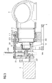
- the rotor-side support member 21 and the central support member 22 are supported in the present embodiment, in each case via an intermediate support 41 on a base support 4, which has a seat for an azimuth bearing of the wind turbine. This is also in the sectional view according to FIG. 3 to recognize.
- the rotor-side carrier element 21 and the central carrier element 22 have seats for a rotor-side rotor shaft bearing 111 or a generator-side rotor shaft bearing 112.
- the configured as a hollow shaft rotor shaft 11 is radially surrounded by the rotor-side support member 21 and the central support member 22, wherein its axis passes through the center of the two support members 21-22.
- the support elements 21-23 may, together with the base support 4 and the intermediate support a supporting structural element for form a nacelle of a wind turbine. In addition, the support elements 21-23 may also be integrated in a transmission housing.
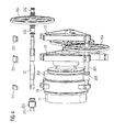
- the three-legged support elements 21-23 of in FIG. 2 shown gear unit have bearing seats for 3 pinion shafts 201.
- the pinion shafts 201 are each mounted by means of corner points of the support elements 21-23 Ritzelwellenlagern 212, 222, 232, both radially and axially.
- the pinion shaft bearings 212, 222, 232 are in turn secured to the support members 21-23 by removable bearing seat members 211, 221, 231. In this way, for example, for maintenance purposes, a simple disassembly of the pinion shafts 201 including connected to the pinion shafts 201 gear parts possible.
- a first gear stage has an externally toothed central gear 202, which is mounted torsionally rigid on the rotor shaft 11 and meshes with 3 pinions 203 of the first gear stage, which are arranged at rotor-side ends of the pinion shafts 201.
- the central gear 202 and the pinions 203 of the first gear stage are arranged axially between the rotor-side carrier element 21 and the central carrier element 22.
- gears 204 of a second gear stage are arranged, which mesh with a central pinion 205 of the second gear stage.
- the gears 204 and the central pinion 205 of the second gear stage are arranged axially between the central support member 22 and the generator-side support member 23.
- Both the generator-side carrier element 23 and the central carrier element 22 each have a bearing seat for a shaft connected to the central pinion 205 of the second gear stage 206 on.
- a gear of a third gear stage is rotatably connected in the present embodiment, which meshes with a pinion on a generator-side output shaft 207.
- a resulting axial offset between the rotor and generator shaft can be used, for example, to carry out control cables for a pitch drive system.
- the central pinion 205 of the second gear stage may be connected directly or via a clutch to a generator shaft.
- FIG. 5 is illustrated that not only the pinion shafts 201 can be easily disassembled for maintenance purposes, but also that the central gear 202 of the first gear stage and the central gear 205 of the second gear stage are accessible in a simple manner.
- the rotor shaft 11 is designed to be pulled out of the carrier elements 21-22, so that the rotor shaft bearings 111, 112 are easily accessible.
- the pinion shafts 201 can be removed from the drive device.
- the central gear 202 of the first gear stage can thus be easily removed by axially displacing the rotor shaft 11 and disassembling an upper pinion shaft 201.
- Assembly and maintenance of a drive train according to the present embodiment are very simple overall.
- all main assemblies such as rotor hub, pinion shafts, intermediate stage, or output, can be pre-assembled individually before they are installed in the drive train. Conversely, during maintenance or repair work, individual assemblies can be easily removed.
- the present drive device With the present drive device, large center distances can be realized. Thus, high transmission ratios can be achieved with only relatively few components. Because of this, the drive device described is particularly suitable for use in wind turbines with powers in the multi-megawatt range. This also applies, for example, to mill drive systems or other heavy duty drive systems, where the rotor shaft corresponds to an output shaft and the generator shaft of a motor shaft.
- 8-10 gear wheels, 10-16 gear bearings and two rotor or output shaft bearings are used for a drive device corresponding to the present embodiment.
- the bearings are preferably designed as plain bearings.
- An oil seal of the drive device takes place, for example, via thin-walled lining elements, which are fastened to carrier elements or other supporting structural elements.
- Load balancing can be ensured in the present drive device via torsionally soft pinion shafts. Furthermore, system deformations can be compensated by long pinion shafts.
- a secure meshing behavior of the second gear stage is preferably ensured by guide elements, which are arranged in the region of the tooth grip between gears and central pinion of the second gear stage.
Landscapes
- Engineering & Computer Science (AREA)
- Life Sciences & Earth Sciences (AREA)
- Sustainable Development (AREA)
- Sustainable Energy (AREA)
- Chemical & Material Sciences (AREA)
- Combustion & Propulsion (AREA)
- Mechanical Engineering (AREA)
- General Engineering & Computer Science (AREA)
- Wind Motors (AREA)
- Connection Of Motors, Electrical Generators, Mechanical Devices, And The Like (AREA)
- Structures Of Non-Positive Displacement Pumps (AREA)
Priority Applications (3)
| Application Number | Priority Date | Filing Date | Title |
|---|---|---|---|
| DK10003558.3T DK2372148T3 (da) | 2010-03-31 | 2010-03-31 | Drivindretning til et vindkraftanlæg |
| AT10003558T ATE557182T1 (de) | 2010-03-31 | 2010-03-31 | Antriebsvorrichtung für eine windkraftanlage |
| EP10003558A EP2372148B1 (fr) | 2010-03-31 | 2010-03-31 | Dispositif d'entraînement pour une éolienne |
Applications Claiming Priority (1)
| Application Number | Priority Date | Filing Date | Title |
|---|---|---|---|
| EP10003558A EP2372148B1 (fr) | 2010-03-31 | 2010-03-31 | Dispositif d'entraînement pour une éolienne |
Publications (2)
| Publication Number | Publication Date |
|---|---|
| EP2372148A1 true EP2372148A1 (fr) | 2011-10-05 |
| EP2372148B1 EP2372148B1 (fr) | 2012-05-09 |
Family
ID=43242828
Family Applications (1)
| Application Number | Title | Priority Date | Filing Date |
|---|---|---|---|
| EP10003558A Not-in-force EP2372148B1 (fr) | 2010-03-31 | 2010-03-31 | Dispositif d'entraînement pour une éolienne |
Country Status (3)
| Country | Link |
|---|---|
| EP (1) | EP2372148B1 (fr) |
| AT (1) | ATE557182T1 (fr) |
| DK (1) | DK2372148T3 (fr) |
Cited By (3)
| Publication number | Priority date | Publication date | Assignee | Title |
|---|---|---|---|---|
| US8591368B2 (en) | 2011-06-30 | 2013-11-26 | Siemens Aktiengesellschaft | Drive system for a wind turbine |
| US8632437B2 (en) | 2011-04-04 | 2014-01-21 | Siemens Aktiengesellschaft | Drive system for a wind turbine |
| US8784252B2 (en) | 2011-06-30 | 2014-07-22 | Siemens Aktiengesellschaft | Drive system for a wind turbine |
Citations (6)
| Publication number | Priority date | Publication date | Assignee | Title |
|---|---|---|---|---|
| WO2001048395A1 (fr) * | 1999-12-24 | 2001-07-05 | Tromelin Jean Pierre | Dispositif de transmission de couple a haut rendement, notamment pour eolienne |
| EP1167818A2 (fr) * | 2000-06-21 | 2002-01-02 | ProRauta | Transmission planétaire à rapport variable |
| US6731017B2 (en) | 2002-06-03 | 2004-05-04 | Clipper Windpower Technology, Inc. | Distributed powertrain that increases electric power generator density |
| EP1279867B1 (fr) | 2001-07-18 | 2005-09-14 | Winergy AG | Transmission à division de puissance |
| WO2008092448A1 (fr) * | 2007-01-31 | 2008-08-07 | Vestas Wind Systems A/S | Éolienne à chaîne dynamique |
| EP1619386B1 (fr) | 2004-07-23 | 2009-09-16 | LOHMANN & STOLTERFOHT GMBH | Transmission pour installation éolienne de haute puissance |
-
2010
- 2010-03-31 AT AT10003558T patent/ATE557182T1/de active
- 2010-03-31 DK DK10003558.3T patent/DK2372148T3/da active
- 2010-03-31 EP EP10003558A patent/EP2372148B1/fr not_active Not-in-force
Patent Citations (6)
| Publication number | Priority date | Publication date | Assignee | Title |
|---|---|---|---|---|
| WO2001048395A1 (fr) * | 1999-12-24 | 2001-07-05 | Tromelin Jean Pierre | Dispositif de transmission de couple a haut rendement, notamment pour eolienne |
| EP1167818A2 (fr) * | 2000-06-21 | 2002-01-02 | ProRauta | Transmission planétaire à rapport variable |
| EP1279867B1 (fr) | 2001-07-18 | 2005-09-14 | Winergy AG | Transmission à division de puissance |
| US6731017B2 (en) | 2002-06-03 | 2004-05-04 | Clipper Windpower Technology, Inc. | Distributed powertrain that increases electric power generator density |
| EP1619386B1 (fr) | 2004-07-23 | 2009-09-16 | LOHMANN & STOLTERFOHT GMBH | Transmission pour installation éolienne de haute puissance |
| WO2008092448A1 (fr) * | 2007-01-31 | 2008-08-07 | Vestas Wind Systems A/S | Éolienne à chaîne dynamique |
Cited By (4)
| Publication number | Priority date | Publication date | Assignee | Title |
|---|---|---|---|---|
| US8632437B2 (en) | 2011-04-04 | 2014-01-21 | Siemens Aktiengesellschaft | Drive system for a wind turbine |
| US9151275B2 (en) | 2011-04-04 | 2015-10-06 | Siemens Aktiengesellschaft | Drive system for a wind turbine |
| US8591368B2 (en) | 2011-06-30 | 2013-11-26 | Siemens Aktiengesellschaft | Drive system for a wind turbine |
| US8784252B2 (en) | 2011-06-30 | 2014-07-22 | Siemens Aktiengesellschaft | Drive system for a wind turbine |
Also Published As
| Publication number | Publication date |
|---|---|
| EP2372148B1 (fr) | 2012-05-09 |
| ATE557182T1 (de) | 2012-05-15 |
| DK2372148T3 (da) | 2012-08-13 |
Similar Documents
| Publication | Publication Date | Title |
|---|---|---|
| EP2508777B1 (fr) | Système de propulsion pour une éolienne | |
| EP2565495B1 (fr) | Drive device with support bolts for a vehicle | |
| EP2431632B1 (fr) | Engrenage à puissance dérivée pour une éolienne | |
| EP1279867A2 (fr) | Transmission à division de puissance | |
| EP2710259B1 (fr) | Transmission d'éolienne | |
| WO2001071220A1 (fr) | Systeme modulaire d'engrenage | |
| EP2541058A1 (fr) | Système de propulsion pour une éolienne | |
| EP2541096A1 (fr) | Système de propulsion pour une éolienne | |
| EP2994646B1 (fr) | Transmission et installation de compresseur à transmission | |
| WO2012143123A1 (fr) | Dispositif pour la transmission de force | |
| EP2295831B1 (fr) | Différentiel | |
| EP3351826A1 (fr) | Boîte de transmission multi-étagée compacte comprenant un engrenage planétaire et une démultiplication harmonique s'y raccordant | |
| WO2015044158A1 (fr) | Porte-satellites | |
| DE102016118877A1 (de) | Mechanische Getriebeanordnung | |
| EP3464894B1 (fr) | Transmission d'éolienne | |
| EP2372148B1 (fr) | Dispositif d'entraînement pour une éolienne | |
| DE102010041474B4 (de) | Leistungsverzweigungsgetriebe | |
| EP2964976A1 (fr) | Ensemble motoréducteur | |
| EP1559928B1 (fr) | Transmission à engranage planetaire pour centrale d'énergie éolienne | |
| DE102012205946A1 (de) | Getriebeeinrichtung, insbesondere für eine Windkraftanlage | |
| AT511862B1 (de) | Energiegewinnungsanlage, insbesondere windkraftanlage | |
| WO2014044277A1 (fr) | Système de transmission | |
| DE102020117956A1 (de) | Planetengetriebe | |
| DE102012014273A1 (de) | Getriebe mit Leistungsverzweigung | |
| DE102010010201A1 (de) | Windkraftanlage mit Getriebe/Generator-Baueinheit |
Legal Events
| Date | Code | Title | Description |
|---|---|---|---|
| PUAI | Public reference made under article 153(3) epc to a published international application that has entered the european phase |
Free format text: ORIGINAL CODE: 0009012 |
|
| 17P | Request for examination filed |
Effective date: 20110110 |
|
| AK | Designated contracting states |
Kind code of ref document: A1 Designated state(s): AT BE BG CH CY CZ DE DK EE ES FI FR GB GR HR HU IE IS IT LI LT LU LV MC MK MT NL NO PL PT RO SE SI SK SM TR |
|
| AX | Request for extension of the european patent |
Extension state: AL BA ME RS |
|
| GRAP | Despatch of communication of intention to grant a patent |
Free format text: ORIGINAL CODE: EPIDOSNIGR1 |
|
| GRAS | Grant fee paid |
Free format text: ORIGINAL CODE: EPIDOSNIGR3 |
|
| GRAA | (expected) grant |
Free format text: ORIGINAL CODE: 0009210 |
|
| AK | Designated contracting states |
Kind code of ref document: B1 Designated state(s): AT BE BG CH CY CZ DE DK EE ES FI FR GB GR HR HU IE IS IT LI LT LU LV MC MK MT NL NO PL PT RO SE SI SK SM TR |
|
| REG | Reference to a national code |
Ref country code: GB Ref legal event code: FG4D Free format text: NOT ENGLISH |
|
| REG | Reference to a national code |
Ref country code: AT Ref legal event code: REF Ref document number: 557182 Country of ref document: AT Kind code of ref document: T Effective date: 20120515 Ref country code: CH Ref legal event code: EP |
|
| REG | Reference to a national code |
Ref country code: DE Ref legal event code: R082 Ref document number: 502010000635 Country of ref document: DE Representative=s name: MAIER, DANIEL OLIVER, DIPL.-ING. UNIV., DE Ref country code: DE Ref legal event code: R082 Ref document number: 502010000635 Country of ref document: DE Representative=s name: DANIEL OLIVER MAIER, DE |
|
| REG | Reference to a national code |
Ref country code: IE Ref legal event code: FG4D Free format text: LANGUAGE OF EP DOCUMENT: GERMAN |
|
| REG | Reference to a national code |
Ref country code: DE Ref legal event code: R096 Ref document number: 502010000635 Country of ref document: DE Effective date: 20120705 |
|
| REG | Reference to a national code |
Ref country code: DK Ref legal event code: T3 |
|
| REG | Reference to a national code |
Ref country code: NL Ref legal event code: VDEP Effective date: 20120509 |
|
| REG | Reference to a national code |
Ref country code: LT Ref legal event code: MG4D Effective date: 20120509 |
|
| PG25 | Lapsed in a contracting state [announced via postgrant information from national office to epo] |
Ref country code: CY Free format text: LAPSE BECAUSE OF FAILURE TO SUBMIT A TRANSLATION OF THE DESCRIPTION OR TO PAY THE FEE WITHIN THE PRESCRIBED TIME-LIMIT Effective date: 20120509 Ref country code: SE Free format text: LAPSE BECAUSE OF FAILURE TO SUBMIT A TRANSLATION OF THE DESCRIPTION OR TO PAY THE FEE WITHIN THE PRESCRIBED TIME-LIMIT Effective date: 20120509 Ref country code: IS Free format text: LAPSE BECAUSE OF FAILURE TO SUBMIT A TRANSLATION OF THE DESCRIPTION OR TO PAY THE FEE WITHIN THE PRESCRIBED TIME-LIMIT Effective date: 20120909 Ref country code: FI Free format text: LAPSE BECAUSE OF FAILURE TO SUBMIT A TRANSLATION OF THE DESCRIPTION OR TO PAY THE FEE WITHIN THE PRESCRIBED TIME-LIMIT Effective date: 20120509 Ref country code: PL Free format text: LAPSE BECAUSE OF FAILURE TO SUBMIT A TRANSLATION OF THE DESCRIPTION OR TO PAY THE FEE WITHIN THE PRESCRIBED TIME-LIMIT Effective date: 20120509 Ref country code: NO Free format text: LAPSE BECAUSE OF FAILURE TO SUBMIT A TRANSLATION OF THE DESCRIPTION OR TO PAY THE FEE WITHIN THE PRESCRIBED TIME-LIMIT Effective date: 20120809 Ref country code: LT Free format text: LAPSE BECAUSE OF FAILURE TO SUBMIT A TRANSLATION OF THE DESCRIPTION OR TO PAY THE FEE WITHIN THE PRESCRIBED TIME-LIMIT Effective date: 20120509 |
|
| PG25 | Lapsed in a contracting state [announced via postgrant information from national office to epo] |
Ref country code: LV Free format text: LAPSE BECAUSE OF FAILURE TO SUBMIT A TRANSLATION OF THE DESCRIPTION OR TO PAY THE FEE WITHIN THE PRESCRIBED TIME-LIMIT Effective date: 20120509 Ref country code: GR Free format text: LAPSE BECAUSE OF FAILURE TO SUBMIT A TRANSLATION OF THE DESCRIPTION OR TO PAY THE FEE WITHIN THE PRESCRIBED TIME-LIMIT Effective date: 20120810 Ref country code: SI Free format text: LAPSE BECAUSE OF FAILURE TO SUBMIT A TRANSLATION OF THE DESCRIPTION OR TO PAY THE FEE WITHIN THE PRESCRIBED TIME-LIMIT Effective date: 20120509 Ref country code: PT Free format text: LAPSE BECAUSE OF FAILURE TO SUBMIT A TRANSLATION OF THE DESCRIPTION OR TO PAY THE FEE WITHIN THE PRESCRIBED TIME-LIMIT Effective date: 20120910 Ref country code: HR Free format text: LAPSE BECAUSE OF FAILURE TO SUBMIT A TRANSLATION OF THE DESCRIPTION OR TO PAY THE FEE WITHIN THE PRESCRIBED TIME-LIMIT Effective date: 20120509 |
|
| PG25 | Lapsed in a contracting state [announced via postgrant information from national office to epo] |
Ref country code: EE Free format text: LAPSE BECAUSE OF FAILURE TO SUBMIT A TRANSLATION OF THE DESCRIPTION OR TO PAY THE FEE WITHIN THE PRESCRIBED TIME-LIMIT Effective date: 20120509 Ref country code: CZ Free format text: LAPSE BECAUSE OF FAILURE TO SUBMIT A TRANSLATION OF THE DESCRIPTION OR TO PAY THE FEE WITHIN THE PRESCRIBED TIME-LIMIT Effective date: 20120509 Ref country code: SK Free format text: LAPSE BECAUSE OF FAILURE TO SUBMIT A TRANSLATION OF THE DESCRIPTION OR TO PAY THE FEE WITHIN THE PRESCRIBED TIME-LIMIT Effective date: 20120509 Ref country code: RO Free format text: LAPSE BECAUSE OF FAILURE TO SUBMIT A TRANSLATION OF THE DESCRIPTION OR TO PAY THE FEE WITHIN THE PRESCRIBED TIME-LIMIT Effective date: 20120509 Ref country code: NL Free format text: LAPSE BECAUSE OF FAILURE TO SUBMIT A TRANSLATION OF THE DESCRIPTION OR TO PAY THE FEE WITHIN THE PRESCRIBED TIME-LIMIT Effective date: 20120509 |
|
| PG25 | Lapsed in a contracting state [announced via postgrant information from national office to epo] |
Ref country code: IT Free format text: LAPSE BECAUSE OF FAILURE TO SUBMIT A TRANSLATION OF THE DESCRIPTION OR TO PAY THE FEE WITHIN THE PRESCRIBED TIME-LIMIT Effective date: 20120509 |
|
| PLBE | No opposition filed within time limit |
Free format text: ORIGINAL CODE: 0009261 |
|
| STAA | Information on the status of an ep patent application or granted ep patent |
Free format text: STATUS: NO OPPOSITION FILED WITHIN TIME LIMIT |
|
| 26N | No opposition filed |
Effective date: 20130212 |
|
| PGFP | Annual fee paid to national office [announced via postgrant information from national office to epo] |
Ref country code: DK Payment date: 20130320 Year of fee payment: 4 Ref country code: FR Payment date: 20130408 Year of fee payment: 4 |
|
| REG | Reference to a national code |
Ref country code: DE Ref legal event code: R097 Ref document number: 502010000635 Country of ref document: DE Effective date: 20130212 |
|
| PG25 | Lapsed in a contracting state [announced via postgrant information from national office to epo] |
Ref country code: BG Free format text: LAPSE BECAUSE OF FAILURE TO SUBMIT A TRANSLATION OF THE DESCRIPTION OR TO PAY THE FEE WITHIN THE PRESCRIBED TIME-LIMIT Effective date: 20120809 |
|
| BERE | Be: lapsed |
Owner name: WINERGY A.G. Effective date: 20130331 |
|
| PG25 | Lapsed in a contracting state [announced via postgrant information from national office to epo] |
Ref country code: ES Free format text: LAPSE BECAUSE OF FAILURE TO SUBMIT A TRANSLATION OF THE DESCRIPTION OR TO PAY THE FEE WITHIN THE PRESCRIBED TIME-LIMIT Effective date: 20120820 Ref country code: MC Free format text: LAPSE BECAUSE OF NON-PAYMENT OF DUE FEES Effective date: 20130331 |
|
| REG | Reference to a national code |
Ref country code: IE Ref legal event code: MM4A |
|
| REG | Reference to a national code |
Ref country code: DE Ref legal event code: R119 Ref document number: 502010000635 Country of ref document: DE Effective date: 20131001 |
|
| PG25 | Lapsed in a contracting state [announced via postgrant information from national office to epo] |
Ref country code: BE Free format text: LAPSE BECAUSE OF NON-PAYMENT OF DUE FEES Effective date: 20130331 Ref country code: DE Free format text: LAPSE BECAUSE OF NON-PAYMENT OF DUE FEES Effective date: 20131001 Ref country code: IE Free format text: LAPSE BECAUSE OF NON-PAYMENT OF DUE FEES Effective date: 20130331 |
|
| PG25 | Lapsed in a contracting state [announced via postgrant information from national office to epo] |
Ref country code: MT Free format text: LAPSE BECAUSE OF FAILURE TO SUBMIT A TRANSLATION OF THE DESCRIPTION OR TO PAY THE FEE WITHIN THE PRESCRIBED TIME-LIMIT Effective date: 20120509 |
|
| REG | Reference to a national code |
Ref country code: DK Ref legal event code: EBP Effective date: 20140331 |
|
| REG | Reference to a national code |
Ref country code: CH Ref legal event code: PL |
|
| GBPC | Gb: european patent ceased through non-payment of renewal fee |
Effective date: 20140331 |
|
| REG | Reference to a national code |
Ref country code: FR Ref legal event code: ST Effective date: 20141128 |
|
| PG25 | Lapsed in a contracting state [announced via postgrant information from national office to epo] |
Ref country code: LI Free format text: LAPSE BECAUSE OF NON-PAYMENT OF DUE FEES Effective date: 20140331 Ref country code: FR Free format text: LAPSE BECAUSE OF NON-PAYMENT OF DUE FEES Effective date: 20140331 Ref country code: CH Free format text: LAPSE BECAUSE OF NON-PAYMENT OF DUE FEES Effective date: 20140331 Ref country code: GB Free format text: LAPSE BECAUSE OF NON-PAYMENT OF DUE FEES Effective date: 20140331 |
|
| PG25 | Lapsed in a contracting state [announced via postgrant information from national office to epo] |
Ref country code: DK Free format text: LAPSE BECAUSE OF NON-PAYMENT OF DUE FEES Effective date: 20140331 |
|
| PG25 | Lapsed in a contracting state [announced via postgrant information from national office to epo] |
Ref country code: SM Free format text: LAPSE BECAUSE OF FAILURE TO SUBMIT A TRANSLATION OF THE DESCRIPTION OR TO PAY THE FEE WITHIN THE PRESCRIBED TIME-LIMIT Effective date: 20120509 |
|
| PG25 | Lapsed in a contracting state [announced via postgrant information from national office to epo] |
Ref country code: TR Free format text: LAPSE BECAUSE OF FAILURE TO SUBMIT A TRANSLATION OF THE DESCRIPTION OR TO PAY THE FEE WITHIN THE PRESCRIBED TIME-LIMIT Effective date: 20120509 |
|
| PG25 | Lapsed in a contracting state [announced via postgrant information from national office to epo] |
Ref country code: MK Free format text: LAPSE BECAUSE OF FAILURE TO SUBMIT A TRANSLATION OF THE DESCRIPTION OR TO PAY THE FEE WITHIN THE PRESCRIBED TIME-LIMIT Effective date: 20120509 Ref country code: LU Free format text: LAPSE BECAUSE OF NON-PAYMENT OF DUE FEES Effective date: 20130331 Ref country code: HU Free format text: LAPSE BECAUSE OF FAILURE TO SUBMIT A TRANSLATION OF THE DESCRIPTION OR TO PAY THE FEE WITHIN THE PRESCRIBED TIME-LIMIT; INVALID AB INITIO Effective date: 20100331 |
|
| REG | Reference to a national code |
Ref country code: AT Ref legal event code: MM01 Ref document number: 557182 Country of ref document: AT Kind code of ref document: T Effective date: 20150331 |
|
| PG25 | Lapsed in a contracting state [announced via postgrant information from national office to epo] |
Ref country code: AT Free format text: LAPSE BECAUSE OF NON-PAYMENT OF DUE FEES Effective date: 20150331 |