EP2541058A1 - Système de propulsion pour une éolienne - Google Patents
Système de propulsion pour une éolienne Download PDFInfo
- Publication number
- EP2541058A1 EP2541058A1 EP11172108A EP11172108A EP2541058A1 EP 2541058 A1 EP2541058 A1 EP 2541058A1 EP 11172108 A EP11172108 A EP 11172108A EP 11172108 A EP11172108 A EP 11172108A EP 2541058 A1 EP2541058 A1 EP 2541058A1
- Authority
- EP
- European Patent Office
- Prior art keywords
- shaft
- gear
- drive system
- unit
- hollow
- Prior art date
- Legal status (The legal status is an assumption and is not a legal conclusion. Google has not performed a legal analysis and makes no representation as to the accuracy of the status listed.)
- Granted
Links
Images



Classifications
-
- F—MECHANICAL ENGINEERING; LIGHTING; HEATING; WEAPONS; BLASTING
- F16—ENGINEERING ELEMENTS AND UNITS; GENERAL MEASURES FOR PRODUCING AND MAINTAINING EFFECTIVE FUNCTIONING OF MACHINES OR INSTALLATIONS; THERMAL INSULATION IN GENERAL
- F16H—GEARING
- F16H1/00—Toothed gearings for conveying rotary motion
- F16H1/28—Toothed gearings for conveying rotary motion with gears having orbital motion
- F16H1/46—Systems consisting of a plurality of gear trains each with orbital gears, i.e. systems having three or more central gears
-
- F—MECHANICAL ENGINEERING; LIGHTING; HEATING; WEAPONS; BLASTING
- F03—MACHINES OR ENGINES FOR LIQUIDS; WIND, SPRING, OR WEIGHT MOTORS; PRODUCING MECHANICAL POWER OR A REACTIVE PROPULSIVE THRUST, NOT OTHERWISE PROVIDED FOR
- F03D—WIND MOTORS
- F03D15/00—Transmission of mechanical power
-
- F—MECHANICAL ENGINEERING; LIGHTING; HEATING; WEAPONS; BLASTING
- F03—MACHINES OR ENGINES FOR LIQUIDS; WIND, SPRING, OR WEIGHT MOTORS; PRODUCING MECHANICAL POWER OR A REACTIVE PROPULSIVE THRUST, NOT OTHERWISE PROVIDED FOR
- F03D—WIND MOTORS
- F03D15/00—Transmission of mechanical power
- F03D15/10—Transmission of mechanical power using gearing not limited to rotary motion, e.g. with oscillating or reciprocating members
-
- F—MECHANICAL ENGINEERING; LIGHTING; HEATING; WEAPONS; BLASTING
- F03—MACHINES OR ENGINES FOR LIQUIDS; WIND, SPRING, OR WEIGHT MOTORS; PRODUCING MECHANICAL POWER OR A REACTIVE PROPULSIVE THRUST, NOT OTHERWISE PROVIDED FOR
- F03D—WIND MOTORS
- F03D7/00—Controlling wind motors
- F03D7/02—Controlling wind motors the wind motors having rotation axis substantially parallel to the air flow entering the rotor
- F03D7/0244—Controlling wind motors the wind motors having rotation axis substantially parallel to the air flow entering the rotor for braking
- F03D7/0248—Controlling wind motors the wind motors having rotation axis substantially parallel to the air flow entering the rotor for braking by mechanical means acting on the power train
-
- F—MECHANICAL ENGINEERING; LIGHTING; HEATING; WEAPONS; BLASTING
- F03—MACHINES OR ENGINES FOR LIQUIDS; WIND, SPRING, OR WEIGHT MOTORS; PRODUCING MECHANICAL POWER OR A REACTIVE PROPULSIVE THRUST, NOT OTHERWISE PROVIDED FOR
- F03D—WIND MOTORS
- F03D80/00—Details, components or accessories not provided for in groups F03D1/00 - F03D17/00
- F03D80/70—Bearing or lubricating arrangements
-
- F—MECHANICAL ENGINEERING; LIGHTING; HEATING; WEAPONS; BLASTING
- F03—MACHINES OR ENGINES FOR LIQUIDS; WIND, SPRING, OR WEIGHT MOTORS; PRODUCING MECHANICAL POWER OR A REACTIVE PROPULSIVE THRUST, NOT OTHERWISE PROVIDED FOR
- F03D—WIND MOTORS
- F03D9/00—Adaptations of wind motors for special use; Combinations of wind motors with apparatus driven thereby; Wind motors specially adapted for installation in particular locations
- F03D9/20—Wind motors characterised by the driven apparatus
- F03D9/25—Wind motors characterised by the driven apparatus the apparatus being an electrical generator
-
- F—MECHANICAL ENGINEERING; LIGHTING; HEATING; WEAPONS; BLASTING
- F16—ENGINEERING ELEMENTS AND UNITS; GENERAL MEASURES FOR PRODUCING AND MAINTAINING EFFECTIVE FUNCTIONING OF MACHINES OR INSTALLATIONS; THERMAL INSULATION IN GENERAL
- F16C—SHAFTS; FLEXIBLE SHAFTS; ELEMENTS OR CRANKSHAFT MECHANISMS; ROTARY BODIES OTHER THAN GEARING ELEMENTS; BEARINGS
- F16C35/00—Rigid support of bearing units; Housings, e.g. caps, covers
- F16C35/04—Rigid support of bearing units; Housings, e.g. caps, covers in the case of ball or roller bearings
- F16C35/042—Housings for rolling element bearings for rotary movement
- F16C35/045—Housings for rolling element bearings for rotary movement with a radial flange to mount the housing
-
- F—MECHANICAL ENGINEERING; LIGHTING; HEATING; WEAPONS; BLASTING
- F16—ENGINEERING ELEMENTS AND UNITS; GENERAL MEASURES FOR PRODUCING AND MAINTAINING EFFECTIVE FUNCTIONING OF MACHINES OR INSTALLATIONS; THERMAL INSULATION IN GENERAL
- F16H—GEARING
- F16H57/00—General details of gearing
- F16H57/02—Gearboxes; Mounting gearing therein
- F16H57/025—Support of gearboxes, e.g. torque arms, or attachment to other devices
-
- F—MECHANICAL ENGINEERING; LIGHTING; HEATING; WEAPONS; BLASTING
- F16—ENGINEERING ELEMENTS AND UNITS; GENERAL MEASURES FOR PRODUCING AND MAINTAINING EFFECTIVE FUNCTIONING OF MACHINES OR INSTALLATIONS; THERMAL INSULATION IN GENERAL
- F16H—GEARING
- F16H57/00—General details of gearing
- F16H57/02—Gearboxes; Mounting gearing therein
- F16H57/028—Gearboxes; Mounting gearing therein characterised by means for reducing vibration or noise
-
- F—MECHANICAL ENGINEERING; LIGHTING; HEATING; WEAPONS; BLASTING
- F16—ENGINEERING ELEMENTS AND UNITS; GENERAL MEASURES FOR PRODUCING AND MAINTAINING EFFECTIVE FUNCTIONING OF MACHINES OR INSTALLATIONS; THERMAL INSULATION IN GENERAL
- F16H—GEARING
- F16H57/00—General details of gearing
- F16H57/08—General details of gearing of gearings with members having orbital motion
-
- F—MECHANICAL ENGINEERING; LIGHTING; HEATING; WEAPONS; BLASTING
- F05—INDEXING SCHEMES RELATING TO ENGINES OR PUMPS IN VARIOUS SUBCLASSES OF CLASSES F01-F04
- F05B—INDEXING SCHEME RELATING TO WIND, SPRING, WEIGHT, INERTIA OR LIKE MOTORS, TO MACHINES OR ENGINES FOR LIQUIDS COVERED BY SUBCLASSES F03B, F03D AND F03G
- F05B2240/00—Components
- F05B2240/90—Mounting on supporting structures or systems
-
- F—MECHANICAL ENGINEERING; LIGHTING; HEATING; WEAPONS; BLASTING
- F05—INDEXING SCHEMES RELATING TO ENGINES OR PUMPS IN VARIOUS SUBCLASSES OF CLASSES F01-F04
- F05B—INDEXING SCHEME RELATING TO WIND, SPRING, WEIGHT, INERTIA OR LIKE MOTORS, TO MACHINES OR ENGINES FOR LIQUIDS COVERED BY SUBCLASSES F03B, F03D AND F03G
- F05B2250/00—Geometry
- F05B2250/30—Arrangement of components
-
- F—MECHANICAL ENGINEERING; LIGHTING; HEATING; WEAPONS; BLASTING
- F05—INDEXING SCHEMES RELATING TO ENGINES OR PUMPS IN VARIOUS SUBCLASSES OF CLASSES F01-F04
- F05B—INDEXING SCHEME RELATING TO WIND, SPRING, WEIGHT, INERTIA OR LIKE MOTORS, TO MACHINES OR ENGINES FOR LIQUIDS COVERED BY SUBCLASSES F03B, F03D AND F03G
- F05B2260/00—Function
- F05B2260/40—Transmission of power
- F05B2260/403—Transmission of power through the shape of the drive components
- F05B2260/4031—Transmission of power through the shape of the drive components as in toothed gearing
- F05B2260/40311—Transmission of power through the shape of the drive components as in toothed gearing of the epicyclic, planetary or differential type
-
- F—MECHANICAL ENGINEERING; LIGHTING; HEATING; WEAPONS; BLASTING
- F16—ENGINEERING ELEMENTS AND UNITS; GENERAL MEASURES FOR PRODUCING AND MAINTAINING EFFECTIVE FUNCTIONING OF MACHINES OR INSTALLATIONS; THERMAL INSULATION IN GENERAL
- F16C—SHAFTS; FLEXIBLE SHAFTS; ELEMENTS OR CRANKSHAFT MECHANISMS; ROTARY BODIES OTHER THAN GEARING ELEMENTS; BEARINGS
- F16C2360/00—Engines or pumps
- F16C2360/31—Wind motors
-
- F—MECHANICAL ENGINEERING; LIGHTING; HEATING; WEAPONS; BLASTING
- F16—ENGINEERING ELEMENTS AND UNITS; GENERAL MEASURES FOR PRODUCING AND MAINTAINING EFFECTIVE FUNCTIONING OF MACHINES OR INSTALLATIONS; THERMAL INSULATION IN GENERAL
- F16C—SHAFTS; FLEXIBLE SHAFTS; ELEMENTS OR CRANKSHAFT MECHANISMS; ROTARY BODIES OTHER THAN GEARING ELEMENTS; BEARINGS
- F16C2361/00—Apparatus or articles in engineering in general
- F16C2361/61—Toothed gear systems, e.g. support of pinion shafts
-
- F—MECHANICAL ENGINEERING; LIGHTING; HEATING; WEAPONS; BLASTING
- F16—ENGINEERING ELEMENTS AND UNITS; GENERAL MEASURES FOR PRODUCING AND MAINTAINING EFFECTIVE FUNCTIONING OF MACHINES OR INSTALLATIONS; THERMAL INSULATION IN GENERAL
- F16C—SHAFTS; FLEXIBLE SHAFTS; ELEMENTS OR CRANKSHAFT MECHANISMS; ROTARY BODIES OTHER THAN GEARING ELEMENTS; BEARINGS
- F16C2361/00—Apparatus or articles in engineering in general
- F16C2361/65—Gear shifting, change speed gear, gear box
-
- Y—GENERAL TAGGING OF NEW TECHNOLOGICAL DEVELOPMENTS; GENERAL TAGGING OF CROSS-SECTIONAL TECHNOLOGIES SPANNING OVER SEVERAL SECTIONS OF THE IPC; TECHNICAL SUBJECTS COVERED BY FORMER USPC CROSS-REFERENCE ART COLLECTIONS [XRACs] AND DIGESTS
- Y02—TECHNOLOGIES OR APPLICATIONS FOR MITIGATION OR ADAPTATION AGAINST CLIMATE CHANGE
- Y02E—REDUCTION OF GREENHOUSE GAS [GHG] EMISSIONS, RELATED TO ENERGY GENERATION, TRANSMISSION OR DISTRIBUTION
- Y02E10/00—Energy generation through renewable energy sources
- Y02E10/70—Wind energy
- Y02E10/72—Wind turbines with rotation axis in wind direction
Definitions
- a large engine drivetrain for wind turbines or mills typically includes system components such as grid connectors, motors or generators, clutches, gears, and drive shafts.
- system components such as grid connectors, motors or generators, clutches, gears, and drive shafts.
- inverters are provided on the network side.
- Brakes are often provided in the form of mechanical brakes on high-speed shaft between the gearbox and the engine or generator, since there braking moments are smaller due to translation.
- a generator-gear unit in which a rotor of the generator is mounted by means of a provided between an inner hollow rotor shaft and a housing stub bearing arrangement. Coil or magnet arrangements of the rotor surround the housing stub radially. Between the inner hollow rotor shaft and a sun shaft, a clutch is provided. The sun shaft does not have its own bearings, but is mounted on the bearing assembly of the rotor.
- EP 1 045 139 A2 discloses a wind turbine with a rotor whose rotor hub is mounted in a arranged on a rotor carrier bearings and connected to a two-stage, a drive stage and an output stage having planetary gear.
- An output shaft of the planetary stage is coupled via a coupling to a generator.
- An inner ring of the rolling bearing is detachably connected to the rotor hub and rotating parts of the planetary gear.
- a housing of the generator with the planetary gear is releasably connected to a drive train module.
- the driveline module is supported on the rotor arm and thus dynamically decoupled.
- a drive device for a wind turbine which comprises at least two at least three-legged support elements for supporting at least 3 pinion shafts.
- the pinion shafts are each mounted by means arranged on corner points of the carrier elements pinion shaft bearings.
- the pinion shaft bearings are fixed by bearing seat members to the support members.
- At least one support element is in addition to the storage of a connectable to a rotor hub connecting shaft configured, which is surrounded by this support member and whose axis extends through the center of the support member.
- a first gear stage of the drive device according to the invention has an externally toothed central wheel.
- the central wheel is mounted on the connecting shaft and meshes with at least 3 pinions of the first gear stage, which are arranged at first ends of the pinion shafts. At the second ends of the pinion shafts at least 3 gears of a second gear stage are arranged, which mesh with a central pinion of the second gear stage.
- WO 2008/031694 Al discloses a mill drive system having a gear unit locatable below a grinding table.
- the transmission comprises at least one planetary stage and has a vertical shaft position.
- an electric motor is integrated, which is connected to a lubricant supply circuit of the transmission, whose rotor and stator have vertically extending axes and whose cooling is carried out by means of circulating through the gear lubricant.
- a mill drive system is described with a can be arranged below a grinding table gear with at least one planetary or spur gear and a built-in a housing of the transmission electric motor.
- the mill drive system comprises a converter with an associated control device for non-interlocking speed control of the motor.
- a geared motor for a mill drive system which comprises a below or laterally of a grinding table can be arranged with at least one planetary or spur gear stage having a vertical or horizontal shaft position.
- an electric motor is integrated, the rotor and stator have parallel to the shaft position of the transmission extending axes.
- An upper bearing cap and a lower bearing cap are mounted on opposite end faces of the rotor and stator, respectively, and include bearing seats for rotor shaft bearings. Between the lower bearing cap and a bottom part of the housing, a collecting tray for coolant is formed.
- a torsional vibration damper is arranged, which comprises a primary part and a torsionally elastic connected to the primary part secondary part.
- a propulsion system for a wind turbine comprising a at least one planetary gear, which has a ring gear, a plurality of planetary gears, a planetary carrier and a sun gear comprising gear unit.
- one of the gear unit is assigned provided first shaft having a connectable with a working machine or rotor shaft coupling flange and is mounted on the planet carrier.
- the gear unit and a motor or generator unit connected to a second shaft of the gear unit are surrounded by a gear housing having a gimbal-shaped circumferentially symmetrical or partially symmetrical suspension for connection to a supporting structural element of the wind turbine.
- the present invention has for its object to provide a mounting-friendly drive system for a wind turbine.
- the drive system has a transmission unit comprising at least one planetary gear, which has a ring gear, a plurality of planet gears, a planet carrier and a sun gear. Furthermore, one of the gear unit associated with the first shaft is provided, which has a connectable to a working machine or rotor shaft coupling flange and is mounted on the planet carrier.
- the gear unit and connected to a second shaft of the gear unit motor or generator unit are surrounded by a transmission housing.
- the motor or generator unit comprises a rotatably connected to a rotor hollow shaft rotor.
- the transmission side End is connected to a transmission hollow shaft.
- a motor or generator-side end portion of the second shaft of the transmission unit is concentrically surrounded by the hollow gear shaft and connected thereto via a arranged within the transmission hollow shaft coupling or clamping connection.
- a transmission housing nozzle is arranged, which concentrically surrounds a transmission-side end portion of the hollow gear shaft and forms a bearing seat for a second shaft of the gear unit associated bearing assembly.
- the hollow rotor shaft and the second shaft of the gear unit are mounted substantially exclusively by means of the bearing assembly on the transmission housing spigot. This allows a particularly compact and easy to maintain design.
- the gear hollow shaft may be connected to the second shaft of the gear unit, for example by a toothed coupling with short or curved teeth.
- the transmission hollow shaft may be connected to the second shaft of the transmission unit by an inner clamping set.
- the inner clamping set comprises, for example, at least one outer ring and one inner ring, which have mutually corresponding conical contact surfaces and by means of a plurality of axially extending clamping screws are braced against each other.
- both the second shaft of the gear unit and the gear hollow shaft and the hollow gear shaft and a Aufsteckflansch are connected to each other, which is releasably connected to a rotor-side end of the flange.
- the hollow gear shaft can be connected to the second shaft of the gear unit by means of an outer clamping set.
- the second shaft of the gear unit is axially substantially half surrounded by the hollow shaft transmission.
- the bearing assembly of the transmission hollow shaft can be arranged axially between the coupling or clamping connection and a rotatably connected to the second shaft of the gear unit sun gear. This allows a decoupling of the bearing assembly relative to acting on the second shaft of the gear unit constraining forces.
- the bearing assembly of the transmission hollow shaft on the transmission housing spigot comprises a double row bearing in X-arrangement.
- the transmission hollow shaft can be manufactured without shaft nut, since the hollow shaft gear does not have to be used for bearing clearance adjustment. This can instead be done via an outer bearing cap.
- the transmission housing connecting piece is integrally formed on an intermediate housing flange arranged between the transmission unit and the motor or generator unit.
- the housing intermediate flange have a bearing seat for a motor or generator side planet carrier bearing.
- a stator shell of the motor or generator unit and a ring gear of a motor or generator side planetary gear can be mounted on the Gephaseus alternflansch in particular.
- the housing intermediate flange may each have a flange extension, on each of which the stator casing or the ring gear of the motor or generator side planetary gear stage is mounted.
- both Flanschfort are graded in terms of their diameter so that they are of a comparable order of magnitude
- the flange extension for the stator shell is the larger of the two.
- the stator extension associated with the flange extension and the ring gear associated with the flange extension are axially spaced apart.
- the coupling flange with the working machine or rotor shaft is elastically connectable.
- a gimbal coupling of a working machine or rotor shaft is possible, in particular with angular offset.
- Such coupling can be realized for example by means of elastic bolts.
- the gearbox has a gimbal-shaped circumferentially symmetric or partially symmetrical suspension for connection to a supporting structural element of the wind turbine.
- the supporting structural element can be, for example, a foundation bearing with a connection to a frame or a nacelle of the wind turbine.
- the transmission unit When using the drive system according to the invention in a wind turbine, the transmission unit is connected to a generator unit. Furthermore, the first shaft of the gear unit in this case is a transmission-side drive shaft. By contrast, the second shaft of the generator unit is a transmission-side output shaft.
- the coupling flange of the transmission-side drive shaft is connectable when using the drive system according to the invention in a wind turbine with a rotor shaft.
- each planetary gear 11, 12 each comprise a ring gear 114, 124, a plurality of planet gears 113, 123, a planet carrier 112, 122 and a sun gear 111, 121.
- the transmission unit 1 is connected via an output shaft 16 of the transmission unit with a generator unit 2 and arranged together with this in a transmission housing 15.
- the transmission unit 1 is a to the planet carrier 112 of the first planetary gear 11th associated with molded drive shaft having a connectable to a rotor shaft coupling flange 14 and is mounted on the planetary carrier 112 of the first planetary gear 11.
- the planet carrier 112 of the first planetary gear 11 are arranged between two planet carrier cheeks and gear housing 15 bearings 115 and 116 which represent a first and a second main bearing of the transmission unit 1.
- the planet carrier 122 of the second planetary gear 12 is supported by two arranged between planet carrier cheeks and gear housing 15 bearings 125 and 126.
- the generator unit 2 comprises a stator 21 and a rotatably connected to a rotor hollow shaft 23 rotor 22.
- the hollow rotor shaft 23 concentrically surrounds a generator end portion of the output shaft 16 and is connected thereto via a disposed within the hollow rotor shaft 23 coupling or clamping connection 232.
- the hollow rotor shaft 23 is arranged axially spaced from the output shaft 16 of the transmission unit 1 and connects axially thereto.
- an electrically insulating, detachable flange 231 is arranged, whose gear-side end is connected to a hollow gear shaft 162.
- a generator-side end portion of the output shaft 16 of the transmission unit 1 is concentrically surrounded by the hollow gear shaft 162 and connected thereto via a clutch or clamping connection 163 arranged within the gear hollow shaft 162.
- a transmission housing 152 is arranged between transmission unit 1 and generator unit 2.
- This housing sleeve 152 concentrically surrounds a transmission-side end section of the gearbox hollow shaft 162 and forms a bearing seat for a bearing arrangement 161 assigned to the output shaft 16 of the gearbox unit 1.
- the output shaft is also provided by means of this bearing arrangement 161 16 stored.
- a pitch tube 17 is arranged in the present embodiment, which extends axially over the entire drive system.
- a rotor-side end of the flange 231 is integrally formed on the hollow rotor shaft 23.
- a transmission-side end of the hollow gear shaft 162 a with the rotor-side end of the flange 231 detachably connected Aufsteckflansch 164 is mounted.
- the output shaft 16 of the transmission unit 1 is axially surrounded substantially half of the generator hollow shaft 162.
- the arranged on the gearbox housing 152 bearing assembly 161 is axially aligned approximately centrally on the connected to the sun gear 121 of the second planetary gear 12 output shaft 16 of the transmission unit 1.
- the bearing assembly 161 of the output shaft 16 on the housing stub 152 preferably comprises a double row bearing in X-arrangement.
- the hollow rotor shaft 23 and the output shaft 16 of the transmission unit 1 are mounted according to a particularly preferred embodiment exclusively by means of the bearing assembly 161 on the housing stub 152.
- One in the FIG. 2 illustrated rear hollow rotor shaft bearing 234 on a side facing away from the gear unit 1 end face of the generator unit 2 is therefore not mandatory and can be omitted in principle.
- a brake disc 233 is rotatably mounted in the present embodiment on the side remote from the gear unit 1 end face of the generator unit 2.
- the brake disc 233 is thus easily accessible for maintenance purposes.
- a brake disc 233 associated caliper 24 is attached to the side facing away from the transmission unit 1 disposed housing cover 153.
- the gear hollow shaft 162 may be connected to the output shaft 16 of the transmission unit 1 by a toothed coupling 163 with short or curved teeth.
- the transmission hollow shaft 162 may be connected to the output shaft 16 of the transmission unit 1 by an inner clamping set.
- the inner clamping set comprises at least in each case an outer ring and an inner ring, which have mutually corresponding conical contact surfaces and by means of a plurality of axially extending clamping screws can be braced against each other.
- both the output shaft 16 of the gear unit 1 and the hollow gear shaft 162 and the hollow shaft 162 and the Aufsteckflansch 164 can be connected to each other, for example, non-positively according to a preferred embodiment.
- the transmission hollow shaft 162 can be widened, for example, by a tension of the outer and inner ring. This then leads to a frictional connection between the hollow gear shaft 162 and Aufsteckflansch 164.
- the Aufsteckflansch 164 for example, by means of a feather key, which is aligned axially on the inner clamping set, are connected to the hollow gear shaft 162.
- the hollow gear shaft 162 may be connected to the output shaft 16 of the gear unit 1 by an outer clamping set.
- a rotor-side end of the flange 231 is screwed, for example, to a flange of the outer clamping set and connected via this with the hollow gear shaft 162.
- an outer clamping set provided on the generator-side end portion of the output shaft 16 of the transmission unit 1, a flange.
- the bearing housing 161 of the output shaft 23 concentrically surrounding housing socket 152 is formed in the present embodiment to a arranged between the gear unit 1 and generator unit 2 Gephase mixflansch 151.
- GeHous alternflansch 151 both a stator shell 211 of the generator unit 2 and the ring gear 124 of the second planetary gear 12 is mounted.
- the intermediate housing flange 151 has a bearing seat for a generator-side planet carrier bearing 126 of the second planetary gear stage 12.
- the Genzous interceptflansch 151 each have a Flanschfortsatz 1511, 1512, on which the stator shell 211 and the ring gear 124 of the second planetary gear 12 is mounted.
- FIG. 4 a variant of a Genosus interceptflansches 151 is shown, in which the stator shell 211 associated Flanschfortsatz 1512 and the ring gear 124 associated Flanschfortsatz 1511 are axially spaced apart.
- the gear housing 15 has a fully gimbal-shaped circumferentially symmetrical or partially symmetrical suspension 13 for connection to a supporting structural element of the wind turbine.
- This supporting structural element is for example a frame or a nacelle of the wind turbine.
- the second planetary gear 12 is dimensioned in terms of their translation so that when you select a divisible by 3 generator pole and optimum design for rated speed substantially identical outside diameter of stator of the generator unit 2 and ring gear 124 of the second planetary gear 12.
- Generator-side bearings of the gear unit 1 are designed electrically insulating. Thus, a flow of current from the transmission unit 1 into a rotor of the generator unit 2 can be avoided.
- An embodiment of the main bearing of the transmission unit 1 can continue to take place without consideration of supporting the following components.
- a torsional wave twist according to the invention by the fully gimbal suspension for the transmission unit 1 has become irrelevant damage.
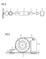
- the generator unit 2 has in the present embodiment, 3 independent winding systems, which are connected to an in FIG. 5 shown full converter 3 are connected.
- the full converter 3 enables network dynamic decoupling and is connected via load disconnector 4 to the generator unit 2 on the one hand and on the other hand to a transformer 5 for power supply in a power grid 6.
- separately isolated generator windings are provided for each pole.
- the 3 independent winding systems are connected outside the transmission housing 15 surrounding the generator unit 2.
- the generator unit is configured 9 to 30-pole, preferably 12 to 24-pin.
- the full gimbal 13 is formed by a gear housing 15 fully radially surrounding ring support.
- the ring support 13 has in the circumferential direction a plurality of substantially equidistantly arranged bores 131, are inserted into the elastic bolt, each having a first end portion.
- the elastic bolts are connected to a corresponding torque arm on the supporting structural element 7 of the wind turbine.
- the corresponding torque arm also includes a ring member having in the circumferential direction substantially equidistantly arranged bores in which the elastic bolts are inserted with a second end portion.
- the corresponding torque arm according to the in FIG. 6 illustrated embodiment, two asymmetrically molded support arms 71, 72, which are each inserted with an end portion in a receptacle 73, 74 on the supporting structure element 7 and connected therewith.
- the elastic bolts of vollkardanischen suspension 13 are axially removable elastomeric bolt.
- the coupling flange 14 has accordingly FIG. 1 in the circumferential direction a plurality of substantially equidistantly arranged holes 141, are inserted into the axially removable elastomeric bolt, which are connected to a corresponding Rotorwellenkupplungsflansch.
- Additional units of the transmission unit 1 such as oil system, radiator and hydraulics, are advantageously mounted directly on the supporting structural element 7 of the wind turbine. About the vollkardanische suspension 13 and an elastic coupling between the rotor shaft and drive shaft of the transmission unit 1, the additional units are thus decoupled from the gear housing 15.
- FIGS. 7 and 8 are each two ring segment supports 13a, 13b shown for partial comprehensive gimbal suspension of the drive system.
- the ring segment supports 13a, 13b each have a plurality of substantially equidistantly arranged bores 131 in the circumferential direction, into which elastic bolts are inserted.
- the elastic bolts with corresponding torque arms 71, 72 are connected to the supporting structure element 7 of the wind turbine.
- the corresponding torque arms 71, 72 are attached directly to the supporting structure element 7 of the wind turbine.
- a mounting capability remains as a conventional two-arm support, without the need for a main frame adaptation to the wind turbine is required. Since a Zwangskraft rejoin already exists, known Elastomerauflager can be used, which are preferably designed completely according to vibration damping criteria.
- the corresponding torque arms on the supporting structural element 7 each have a ring segment with circumferentially substantially equidistantly arranged bores 131.
- the elastic bolts are used, the same as in the embodiment accordingly FIG. 6 can be configured as axially removable elastomer bolt.
- symmetry axis of the torque arms and axis of rotation of the drive system intersect.
- the coupling flange may have a plurality of staggered rows of holes, in the bores of which axially removable elastomeric bolts are inserted.
- the coupling flange can be made smaller in terms of its outer diameter at the same bore spacings.
- the elastomeric bolts may have different rigidities adapted to the diameter and flange type.
- the coupling flange with smaller diameter compared to the suspension may be made of a harder material, while the suspension may be made of a softer material.
- the use of the drive system described is not limited to wind turbines, but also, for example, in mill drive systems conceivable in which the generator unit is replaced by a motor unit.
Landscapes
- Engineering & Computer Science (AREA)
- General Engineering & Computer Science (AREA)
- Mechanical Engineering (AREA)
- Life Sciences & Earth Sciences (AREA)
- Sustainable Development (AREA)
- Sustainable Energy (AREA)
- Chemical & Material Sciences (AREA)
- Combustion & Propulsion (AREA)
- Power Engineering (AREA)
- Wind Motors (AREA)
- Retarders (AREA)
- Connection Of Motors, Electrical Generators, Mechanical Devices, And The Like (AREA)
Priority Applications (4)
| Application Number | Priority Date | Filing Date | Title |
|---|---|---|---|
| ES11172108.0T ES2475993T3 (es) | 2011-06-30 | 2011-06-30 | Sistema de accionamiento para una turbina e�lica |
| EP11172108.0A EP2541058B1 (fr) | 2011-06-30 | 2011-06-30 | Système de propulsion pour une éolienne |
| CN201210213831.8A CN102852738B (zh) | 2011-06-30 | 2012-06-25 | 用于风力发电设备的驱动系统 |
| US13/537,651 US8591368B2 (en) | 2011-06-30 | 2012-06-29 | Drive system for a wind turbine |
Applications Claiming Priority (1)
| Application Number | Priority Date | Filing Date | Title |
|---|---|---|---|
| EP11172108.0A EP2541058B1 (fr) | 2011-06-30 | 2011-06-30 | Système de propulsion pour une éolienne |
Publications (2)
| Publication Number | Publication Date |
|---|---|
| EP2541058A1 true EP2541058A1 (fr) | 2013-01-02 |
| EP2541058B1 EP2541058B1 (fr) | 2014-04-30 |
Family
ID=44840371
Family Applications (1)
| Application Number | Title | Priority Date | Filing Date |
|---|---|---|---|
| EP11172108.0A Active EP2541058B1 (fr) | 2011-06-30 | 2011-06-30 | Système de propulsion pour une éolienne |
Country Status (4)
| Country | Link |
|---|---|
| US (1) | US8591368B2 (fr) |
| EP (1) | EP2541058B1 (fr) |
| CN (1) | CN102852738B (fr) |
| ES (1) | ES2475993T3 (fr) |
Cited By (11)
| Publication number | Priority date | Publication date | Assignee | Title |
|---|---|---|---|---|
| US9051922B2 (en) | 2011-09-26 | 2015-06-09 | Siemens Aktiengesellschaft | Drive system for a wind turbine |
| EP2933483A1 (fr) | 2014-04-15 | 2015-10-21 | Siemens Aktiengesellschaft | Système d'entraînement d'une éolienne |
| WO2016015935A1 (fr) * | 2014-07-29 | 2016-02-04 | Zf Friedrichshafen Ag | Accouplement modulaire d'une transmission d'éolienne équipé d'un générateur et procédé |
| EP3587863A1 (fr) * | 2018-06-25 | 2020-01-01 | Flender GmbH | Engrenage planétaire, chaîne cinématique, éolienne et application industrielle |
| DE102018218936A1 (de) * | 2018-11-07 | 2020-05-07 | Zf Friedrichshafen Ag | Asymmetrische Drehmomentstützen |
| EP3653907A1 (fr) * | 2018-11-15 | 2020-05-20 | ZF Friedrichshafen AG | Caisson de stockage pour éoliennes |
| EP3795825A1 (fr) * | 2019-09-20 | 2021-03-24 | ZF Friedrichshafen AG | Tube de traversée isolé |
| EP3795862A1 (fr) * | 2019-09-20 | 2021-03-24 | ZF Friedrichshafen AG | Tube de traversée isolé |
| EP3971446A1 (fr) | 2020-09-16 | 2022-03-23 | Siemens Aktiengesellschaft | Modes générateur, chaine cinématique, éolienne et produit programme informatique |
| US12085163B2 (en) | 2021-02-26 | 2024-09-10 | Flender Gmbh | Transmission and method for operating a transmission |
| EP4729767A1 (fr) | 2024-10-16 | 2026-04-22 | Flender GmbH | Interface de composant entre une unité de transmission et une unité de générateur |
Families Citing this family (10)
| Publication number | Priority date | Publication date | Assignee | Title |
|---|---|---|---|---|
| EP2494196B1 (fr) * | 2009-10-28 | 2019-01-09 | Vestas Wind Systems A/S | Installation éolienne et procédés permettant d'utiliser un bâti dans une installation éolienne |
| EP2910398B1 (fr) * | 2014-02-21 | 2017-10-04 | Siemens Aktiengesellschaft | Machine à entraînement par chaîne |
| EP2975299A1 (fr) | 2014-07-18 | 2016-01-20 | Siemens Aktiengesellschaft | Palier à glissement pour support épicycloïdal |
| KR101703614B1 (ko) * | 2015-09-10 | 2017-02-07 | 현대자동차 주식회사 | 구동모터와 감속기의 연결 구조 |
| EP3284975B1 (fr) | 2016-08-19 | 2020-02-26 | Flender GmbH | Axe planetaire |
| DE102017206510A1 (de) * | 2017-04-18 | 2018-10-18 | Volkswagen Aktiengesellschaft | Getriebestruktur für ein seriell/paralleles Hybridfahrzeug |
| US11536361B2 (en) * | 2018-03-08 | 2022-12-27 | General Electric Company | Modular gearbox for wind turbine |
| CN114294376B (zh) * | 2021-12-23 | 2024-07-02 | 银川威力传动技术股份有限公司 | 风电偏航变桨驱动输入结构 |
| CN114448168B (zh) * | 2022-03-14 | 2024-08-30 | 常州优谷新能源科技股份有限公司 | 15mw半直驱发电机 |
| EP4345300A1 (fr) * | 2022-09-28 | 2024-04-03 | Flender GmbH | Tube de pas fiable pour une régulation de l'angle de réglage de pale d'une éolienne |
Citations (9)
| Publication number | Priority date | Publication date | Assignee | Title |
|---|---|---|---|---|
| JPH08312522A (ja) * | 1995-05-16 | 1996-11-26 | Mitsubishi Heavy Ind Ltd | 風力発電装置 |
| EP1045139A2 (fr) | 1999-04-12 | 2000-10-18 | A. Friedr. Flender Ag | Eolienne |
| DE10318945B3 (de) * | 2003-04-26 | 2004-10-28 | Aerodyn Gmbh | Getriebeanordnung für Windenergieanlagen |
| DE102004022299A1 (de) * | 2004-05-04 | 2005-12-01 | Stemmann-Technik Gmbh | Windenergieanlage |
| WO2008031694A1 (fr) | 2006-09-14 | 2008-03-20 | Siemens Aktiengesellschaft | Broyeur pour le moulage de gros matériaux en vrac, du genre pierres, avec moteur parallèle à l'axe |
| EP2031273A2 (fr) | 2007-08-27 | 2009-03-04 | General Electric Company | Ensemble de transmission à entraînement forcé à vitesse moyenne intégrée |
| US20100062888A1 (en) * | 2008-09-05 | 2010-03-11 | General Electric Company | System and assembly for power transmission and generation in a wind turbine |
| EP2295147A1 (fr) | 2009-09-10 | 2011-03-16 | Siemens Aktiengesellschaft | Système d'entraînement de moulin |
| US20110068583A1 (en) * | 2009-09-24 | 2011-03-24 | General Electric Company | Rotor-shaft integrated generator drive apparatus |
Family Cites Families (9)
| Publication number | Priority date | Publication date | Assignee | Title |
|---|---|---|---|---|
| US5663600A (en) * | 1995-03-03 | 1997-09-02 | General Electric Company | Variable speed wind turbine with radially oriented gear drive |
| ES2375140T3 (es) * | 2004-02-27 | 2012-02-27 | Repower Systems Se | Instalación de pararrayos para plantas de energ�?a eólica. |
| EP2142826B1 (fr) * | 2007-04-24 | 2015-10-28 | Fallbrook Intellectual Property Company LLC | Entraînements de traction électrique |
| DE102008063868B3 (de) | 2008-12-19 | 2010-06-10 | Winergy Ag | Planetengetriebe für eine Windkraftanlage |
| US8376708B2 (en) * | 2009-06-30 | 2013-02-19 | General Electric Company | Drivetrain system for a wind turbine generator and method of assembling the same |
| EP2366988A1 (fr) | 2010-03-19 | 2011-09-21 | Winergy AG | Procédé et dispositif de détection de couple dans un engrenage au moyen d'un capteur de vibrations |
| ATE557182T1 (de) | 2010-03-31 | 2012-05-15 | Winergy Ag | Antriebsvorrichtung für eine windkraftanlage |
| ES2393850T3 (es) | 2010-04-30 | 2012-12-28 | Winergy Ag | Engranaje planetario (epicicloidal) para un aerogenerador |
| EP2388498B1 (fr) | 2010-05-21 | 2012-09-19 | Winergy AG | Transmission pour une éolienne |
-
2011
- 2011-06-30 EP EP11172108.0A patent/EP2541058B1/fr active Active
- 2011-06-30 ES ES11172108.0T patent/ES2475993T3/es active Active
-
2012
- 2012-06-25 CN CN201210213831.8A patent/CN102852738B/zh active Active
- 2012-06-29 US US13/537,651 patent/US8591368B2/en active Active
Patent Citations (9)
| Publication number | Priority date | Publication date | Assignee | Title |
|---|---|---|---|---|
| JPH08312522A (ja) * | 1995-05-16 | 1996-11-26 | Mitsubishi Heavy Ind Ltd | 風力発電装置 |
| EP1045139A2 (fr) | 1999-04-12 | 2000-10-18 | A. Friedr. Flender Ag | Eolienne |
| DE10318945B3 (de) * | 2003-04-26 | 2004-10-28 | Aerodyn Gmbh | Getriebeanordnung für Windenergieanlagen |
| DE102004022299A1 (de) * | 2004-05-04 | 2005-12-01 | Stemmann-Technik Gmbh | Windenergieanlage |
| WO2008031694A1 (fr) | 2006-09-14 | 2008-03-20 | Siemens Aktiengesellschaft | Broyeur pour le moulage de gros matériaux en vrac, du genre pierres, avec moteur parallèle à l'axe |
| EP2031273A2 (fr) | 2007-08-27 | 2009-03-04 | General Electric Company | Ensemble de transmission à entraînement forcé à vitesse moyenne intégrée |
| US20100062888A1 (en) * | 2008-09-05 | 2010-03-11 | General Electric Company | System and assembly for power transmission and generation in a wind turbine |
| EP2295147A1 (fr) | 2009-09-10 | 2011-03-16 | Siemens Aktiengesellschaft | Système d'entraînement de moulin |
| US20110068583A1 (en) * | 2009-09-24 | 2011-03-24 | General Electric Company | Rotor-shaft integrated generator drive apparatus |
Cited By (22)
| Publication number | Priority date | Publication date | Assignee | Title |
|---|---|---|---|---|
| US9051922B2 (en) | 2011-09-26 | 2015-06-09 | Siemens Aktiengesellschaft | Drive system for a wind turbine |
| EP2933483A1 (fr) | 2014-04-15 | 2015-10-21 | Siemens Aktiengesellschaft | Système d'entraînement d'une éolienne |
| US10316826B2 (en) | 2014-04-15 | 2019-06-11 | Siemens Aktiengesellschaft | Drive system of a wind turbine |
| WO2016015935A1 (fr) * | 2014-07-29 | 2016-02-04 | Zf Friedrichshafen Ag | Accouplement modulaire d'une transmission d'éolienne équipé d'un générateur et procédé |
| EP3587863A1 (fr) * | 2018-06-25 | 2020-01-01 | Flender GmbH | Engrenage planétaire, chaîne cinématique, éolienne et application industrielle |
| WO2020001942A1 (fr) * | 2018-06-25 | 2020-01-02 | Flender Gmbh | Engrenage planétaire, chaîne cinématique, éolienne et application industrielle |
| DE102018218936A1 (de) * | 2018-11-07 | 2020-05-07 | Zf Friedrichshafen Ag | Asymmetrische Drehmomentstützen |
| US12601397B2 (en) | 2018-11-07 | 2026-04-14 | Zf Friedrichshafen Ag | Asymmetric torque brackets |
| EP3653907A1 (fr) * | 2018-11-15 | 2020-05-20 | ZF Friedrichshafen AG | Caisson de stockage pour éoliennes |
| WO2020099044A1 (fr) * | 2018-11-15 | 2020-05-22 | Zf Friedrichshafen Ag | Cassette de palier pour eoliennes |
| EP3795862A1 (fr) * | 2019-09-20 | 2021-03-24 | ZF Friedrichshafen AG | Tube de traversée isolé |
| WO2021052694A1 (fr) * | 2019-09-20 | 2021-03-25 | Zf Friedrichshafen Ag | Tube à pas isolé |
| WO2021052693A1 (fr) * | 2019-09-20 | 2021-03-25 | Zf Friedrichshafen Ag | Tube de calage isolé |
| EP3795862B1 (fr) | 2019-09-20 | 2021-12-08 | ZF Friedrichshafen AG | Tube de traversée isolé |
| CN114341525A (zh) * | 2019-09-20 | 2022-04-12 | Zf 腓德烈斯哈芬股份公司 | 绝缘的穿通管 |
| US12123405B2 (en) | 2019-09-20 | 2024-10-22 | Zf Friedrichshafen Ag | Insulated pitch tube |
| EP3795862B2 (fr) † | 2019-09-20 | 2024-12-18 | ZF Friedrichshafen AG | Tube de traversée isolé |
| US12276255B2 (en) | 2019-09-20 | 2025-04-15 | Zf Friedrichshafen Ag | Insulated pitch tube |
| EP3795825A1 (fr) * | 2019-09-20 | 2021-03-24 | ZF Friedrichshafen AG | Tube de traversée isolé |
| EP3971446A1 (fr) | 2020-09-16 | 2022-03-23 | Siemens Aktiengesellschaft | Modes générateur, chaine cinématique, éolienne et produit programme informatique |
| US12085163B2 (en) | 2021-02-26 | 2024-09-10 | Flender Gmbh | Transmission and method for operating a transmission |
| EP4729767A1 (fr) | 2024-10-16 | 2026-04-22 | Flender GmbH | Interface de composant entre une unité de transmission et une unité de générateur |
Also Published As
| Publication number | Publication date |
|---|---|
| CN102852738B (zh) | 2015-08-19 |
| CN102852738A (zh) | 2013-01-02 |
| EP2541058B1 (fr) | 2014-04-30 |
| US20130165288A1 (en) | 2013-06-27 |
| US8591368B2 (en) | 2013-11-26 |
| ES2475993T3 (es) | 2014-07-11 |
Similar Documents
| Publication | Publication Date | Title |
|---|---|---|
| EP2541058B1 (fr) | Système de propulsion pour une éolienne | |
| EP2508777B1 (fr) | Système de propulsion pour une éolienne | |
| EP2573386B1 (fr) | Système de transmission pour une éolienne | |
| EP2541096A1 (fr) | Système de propulsion pour une éolienne | |
| EP2097641B1 (fr) | Transmission d'éolienne à couple divisé | |
| EP2661554B1 (fr) | Éolienne | |
| EP2379879B1 (fr) | Ensemble génératrice pour éolienne | |
| WO2015158753A1 (fr) | Système d'entraînement d'une éolienne | |
| WO2013113487A1 (fr) | Unité palier, notamment pour une éolienne | |
| WO2009043330A2 (fr) | Désaccouplement de l'arbre d'entraînement et de l'arbre entraîné par une transmission à deux étages d'une éolienne | |
| DE102011106535B4 (de) | Antriebsstrang einer Strömungskraftanlage | |
| WO2009100720A2 (fr) | Dispositif de limitation de couple dans une chaîne cinématique | |
| EP3767102B1 (fr) | Ensemble de train d'entrainement | |
| EP2379882B1 (fr) | Installation exploitant une force de flux | |
| DE102012205946A1 (de) | Getriebeeinrichtung, insbesondere für eine Windkraftanlage | |
| EP2514076A1 (fr) | Ensemble génératrice pour une éolienne | |
| AT511862B1 (de) | Energiegewinnungsanlage, insbesondere windkraftanlage | |
| WO2023165769A1 (fr) | Ensemble engrenage planétaire comprenant un arbre solaire monté dans/sur le porte-satellites, transmission industrielle et utilisation correspondantes | |
| EP2372148A1 (fr) | Dispositif d'entraînement pour une éolienne | |
| WO2010121586A2 (fr) | Chaîne cinématique pour éolienne, nacelle d'éolienne, éolienne et parc d'éoliennes ainsi que conteneur standard | |
| EP2836707B1 (fr) | Eolienne avec un generateur inversé du type outrunner | |
| EP4729767A1 (fr) | Interface de composant entre une unité de transmission et une unité de générateur | |
| DE102012213911A1 (de) | Windenergieanlage |
Legal Events
| Date | Code | Title | Description |
|---|---|---|---|
| PUAI | Public reference made under article 153(3) epc to a published international application that has entered the european phase |
Free format text: ORIGINAL CODE: 0009012 |
|
| 17P | Request for examination filed |
Effective date: 20111123 |
|
| AK | Designated contracting states |
Kind code of ref document: A1 Designated state(s): AL AT BE BG CH CY CZ DE DK EE ES FI FR GB GR HR HU IE IS IT LI LT LU LV MC MK MT NL NO PL PT RO RS SE SI SK SM TR |
|
| AX | Request for extension of the european patent |
Extension state: BA ME |
|
| RAP1 | Party data changed (applicant data changed or rights of an application transferred) |
Owner name: SIEMENS AKTIENGESELLSCHAFT |
|
| RIC1 | Information provided on ipc code assigned before grant |
Ipc: F03D 9/00 20060101ALI20130522BHEP Ipc: F16H 1/46 20060101ALI20130522BHEP Ipc: F03D 11/02 20060101AFI20130522BHEP |
|
| GRAP | Despatch of communication of intention to grant a patent |
Free format text: ORIGINAL CODE: EPIDOSNIGR1 |
|
| INTG | Intention to grant announced |
Effective date: 20130719 |
|
| GRAS | Grant fee paid |
Free format text: ORIGINAL CODE: EPIDOSNIGR3 |
|
| GRAP | Despatch of communication of intention to grant a patent |
Free format text: ORIGINAL CODE: EPIDOSNIGR1 |
|
| INTG | Intention to grant announced |
Effective date: 20140107 |
|
| GRAA | (expected) grant |
Free format text: ORIGINAL CODE: 0009210 |
|
| AK | Designated contracting states |
Kind code of ref document: B1 Designated state(s): AL AT BE BG CH CY CZ DE DK EE ES FI FR GB GR HR HU IE IS IT LI LT LU LV MC MK MT NL NO PL PT RO RS SE SI SK SM TR |
|
| REG | Reference to a national code |
Ref country code: GB Ref legal event code: FG4D Free format text: NOT ENGLISH Ref country code: CH Ref legal event code: EP |
|
| REG | Reference to a national code |
Ref country code: AT Ref legal event code: REF Ref document number: 665334 Country of ref document: AT Kind code of ref document: T Effective date: 20140515 |
|
| REG | Reference to a national code |
Ref country code: IE Ref legal event code: FG4D Free format text: LANGUAGE OF EP DOCUMENT: GERMAN |
|
| REG | Reference to a national code |
Ref country code: DE Ref legal event code: R096 Ref document number: 502011002882 Country of ref document: DE Effective date: 20140612 |
|
| REG | Reference to a national code |
Ref country code: ES Ref legal event code: FG2A Ref document number: 2475993 Country of ref document: ES Kind code of ref document: T3 Effective date: 20140711 |
|
| REG | Reference to a national code |
Ref country code: SE Ref legal event code: TRGR |
|
| REG | Reference to a national code |
Ref country code: LT Ref legal event code: MG4D |
|
| REG | Reference to a national code |
Ref country code: NL Ref legal event code: VDEP Effective date: 20140430 |
|
| PG25 | Lapsed in a contracting state [announced via postgrant information from national office to epo] |
Ref country code: NO Free format text: LAPSE BECAUSE OF FAILURE TO SUBMIT A TRANSLATION OF THE DESCRIPTION OR TO PAY THE FEE WITHIN THE PRESCRIBED TIME-LIMIT Effective date: 20140730 Ref country code: BG Free format text: LAPSE BECAUSE OF FAILURE TO SUBMIT A TRANSLATION OF THE DESCRIPTION OR TO PAY THE FEE WITHIN THE PRESCRIBED TIME-LIMIT Effective date: 20140730 Ref country code: NL Free format text: LAPSE BECAUSE OF FAILURE TO SUBMIT A TRANSLATION OF THE DESCRIPTION OR TO PAY THE FEE WITHIN THE PRESCRIBED TIME-LIMIT Effective date: 20140430 Ref country code: LT Free format text: LAPSE BECAUSE OF FAILURE TO SUBMIT A TRANSLATION OF THE DESCRIPTION OR TO PAY THE FEE WITHIN THE PRESCRIBED TIME-LIMIT Effective date: 20140430 Ref country code: GR Free format text: LAPSE BECAUSE OF FAILURE TO SUBMIT A TRANSLATION OF THE DESCRIPTION OR TO PAY THE FEE WITHIN THE PRESCRIBED TIME-LIMIT Effective date: 20140731 Ref country code: CY Free format text: LAPSE BECAUSE OF FAILURE TO SUBMIT A TRANSLATION OF THE DESCRIPTION OR TO PAY THE FEE WITHIN THE PRESCRIBED TIME-LIMIT Effective date: 20140430 Ref country code: IS Free format text: LAPSE BECAUSE OF FAILURE TO SUBMIT A TRANSLATION OF THE DESCRIPTION OR TO PAY THE FEE WITHIN THE PRESCRIBED TIME-LIMIT Effective date: 20140830 |
|
| PG25 | Lapsed in a contracting state [announced via postgrant information from national office to epo] |
Ref country code: HR Free format text: LAPSE BECAUSE OF FAILURE TO SUBMIT A TRANSLATION OF THE DESCRIPTION OR TO PAY THE FEE WITHIN THE PRESCRIBED TIME-LIMIT Effective date: 20140430 Ref country code: LV Free format text: LAPSE BECAUSE OF FAILURE TO SUBMIT A TRANSLATION OF THE DESCRIPTION OR TO PAY THE FEE WITHIN THE PRESCRIBED TIME-LIMIT Effective date: 20140430 Ref country code: PL Free format text: LAPSE BECAUSE OF FAILURE TO SUBMIT A TRANSLATION OF THE DESCRIPTION OR TO PAY THE FEE WITHIN THE PRESCRIBED TIME-LIMIT Effective date: 20140430 Ref country code: RS Free format text: LAPSE BECAUSE OF FAILURE TO SUBMIT A TRANSLATION OF THE DESCRIPTION OR TO PAY THE FEE WITHIN THE PRESCRIBED TIME-LIMIT Effective date: 20140430 |
|
| PG25 | Lapsed in a contracting state [announced via postgrant information from national office to epo] |
Ref country code: PT Free format text: LAPSE BECAUSE OF FAILURE TO SUBMIT A TRANSLATION OF THE DESCRIPTION OR TO PAY THE FEE WITHIN THE PRESCRIBED TIME-LIMIT Effective date: 20140901 |
|
| PG25 | Lapsed in a contracting state [announced via postgrant information from national office to epo] |
Ref country code: SK Free format text: LAPSE BECAUSE OF FAILURE TO SUBMIT A TRANSLATION OF THE DESCRIPTION OR TO PAY THE FEE WITHIN THE PRESCRIBED TIME-LIMIT Effective date: 20140430 Ref country code: EE Free format text: LAPSE BECAUSE OF FAILURE TO SUBMIT A TRANSLATION OF THE DESCRIPTION OR TO PAY THE FEE WITHIN THE PRESCRIBED TIME-LIMIT Effective date: 20140430 Ref country code: DK Free format text: LAPSE BECAUSE OF FAILURE TO SUBMIT A TRANSLATION OF THE DESCRIPTION OR TO PAY THE FEE WITHIN THE PRESCRIBED TIME-LIMIT Effective date: 20140430 Ref country code: CZ Free format text: LAPSE BECAUSE OF FAILURE TO SUBMIT A TRANSLATION OF THE DESCRIPTION OR TO PAY THE FEE WITHIN THE PRESCRIBED TIME-LIMIT Effective date: 20140430 Ref country code: MC Free format text: LAPSE BECAUSE OF FAILURE TO SUBMIT A TRANSLATION OF THE DESCRIPTION OR TO PAY THE FEE WITHIN THE PRESCRIBED TIME-LIMIT Effective date: 20140430 Ref country code: LU Free format text: LAPSE BECAUSE OF FAILURE TO SUBMIT A TRANSLATION OF THE DESCRIPTION OR TO PAY THE FEE WITHIN THE PRESCRIBED TIME-LIMIT Effective date: 20140630 Ref country code: RO Free format text: LAPSE BECAUSE OF FAILURE TO SUBMIT A TRANSLATION OF THE DESCRIPTION OR TO PAY THE FEE WITHIN THE PRESCRIBED TIME-LIMIT Effective date: 20140430 |
|
| REG | Reference to a national code |
Ref country code: CH Ref legal event code: PL |
|
| REG | Reference to a national code |
Ref country code: DE Ref legal event code: R097 Ref document number: 502011002882 Country of ref document: DE |
|
| PLBE | No opposition filed within time limit |
Free format text: ORIGINAL CODE: 0009261 |
|
| STAA | Information on the status of an ep patent application or granted ep patent |
Free format text: STATUS: NO OPPOSITION FILED WITHIN TIME LIMIT |
|
| REG | Reference to a national code |
Ref country code: IE Ref legal event code: MM4A |
|
| 26N | No opposition filed |
Effective date: 20150202 |
|
| PG25 | Lapsed in a contracting state [announced via postgrant information from national office to epo] |
Ref country code: CH Free format text: LAPSE BECAUSE OF NON-PAYMENT OF DUE FEES Effective date: 20140630 Ref country code: IE Free format text: LAPSE BECAUSE OF NON-PAYMENT OF DUE FEES Effective date: 20140630 Ref country code: LI Free format text: LAPSE BECAUSE OF NON-PAYMENT OF DUE FEES Effective date: 20140630 |
|
| REG | Reference to a national code |
Ref country code: DE Ref legal event code: R097 Ref document number: 502011002882 Country of ref document: DE Effective date: 20150202 |
|
| PG25 | Lapsed in a contracting state [announced via postgrant information from national office to epo] |
Ref country code: SI Free format text: LAPSE BECAUSE OF FAILURE TO SUBMIT A TRANSLATION OF THE DESCRIPTION OR TO PAY THE FEE WITHIN THE PRESCRIBED TIME-LIMIT Effective date: 20140430 |
|
| PG25 | Lapsed in a contracting state [announced via postgrant information from national office to epo] |
Ref country code: MT Free format text: LAPSE BECAUSE OF FAILURE TO SUBMIT A TRANSLATION OF THE DESCRIPTION OR TO PAY THE FEE WITHIN THE PRESCRIBED TIME-LIMIT Effective date: 20140430 |
|
| PG25 | Lapsed in a contracting state [announced via postgrant information from national office to epo] |
Ref country code: SM Free format text: LAPSE BECAUSE OF FAILURE TO SUBMIT A TRANSLATION OF THE DESCRIPTION OR TO PAY THE FEE WITHIN THE PRESCRIBED TIME-LIMIT Effective date: 20140430 |
|
| REG | Reference to a national code |
Ref country code: FR Ref legal event code: PLFP Year of fee payment: 6 |
|
| PG25 | Lapsed in a contracting state [announced via postgrant information from national office to epo] |
Ref country code: TR Free format text: LAPSE BECAUSE OF FAILURE TO SUBMIT A TRANSLATION OF THE DESCRIPTION OR TO PAY THE FEE WITHIN THE PRESCRIBED TIME-LIMIT Effective date: 20140430 Ref country code: HU Free format text: LAPSE BECAUSE OF FAILURE TO SUBMIT A TRANSLATION OF THE DESCRIPTION OR TO PAY THE FEE WITHIN THE PRESCRIBED TIME-LIMIT; INVALID AB INITIO Effective date: 20110630 |
|
| REG | Reference to a national code |
Ref country code: FR Ref legal event code: PLFP Year of fee payment: 7 |
|
| REG | Reference to a national code |
Ref country code: AT Ref legal event code: MM01 Ref document number: 665334 Country of ref document: AT Kind code of ref document: T Effective date: 20160630 |
|
| PG25 | Lapsed in a contracting state [announced via postgrant information from national office to epo] |
Ref country code: AT Free format text: LAPSE BECAUSE OF NON-PAYMENT OF DUE FEES Effective date: 20160630 |
|
| REG | Reference to a national code |
Ref country code: FR Ref legal event code: PLFP Year of fee payment: 8 |
|
| PG25 | Lapsed in a contracting state [announced via postgrant information from national office to epo] |
Ref country code: MK Free format text: LAPSE BECAUSE OF FAILURE TO SUBMIT A TRANSLATION OF THE DESCRIPTION OR TO PAY THE FEE WITHIN THE PRESCRIBED TIME-LIMIT Effective date: 20140430 |
|
| PG25 | Lapsed in a contracting state [announced via postgrant information from national office to epo] |
Ref country code: AL Free format text: LAPSE BECAUSE OF FAILURE TO SUBMIT A TRANSLATION OF THE DESCRIPTION OR TO PAY THE FEE WITHIN THE PRESCRIBED TIME-LIMIT Effective date: 20140430 |
|
| REG | Reference to a national code |
Ref country code: DE Ref legal event code: R081 Ref document number: 502011002882 Country of ref document: DE Owner name: FLENDER GMBH, DE Free format text: FORMER OWNER: SIEMENS AG, 80333 MUENCHEN, DE |
|
| REG | Reference to a national code |
Ref country code: FI Ref legal event code: PCE Owner name: FLENDER GMBH |
|
| REG | Reference to a national code |
Ref country code: GB Ref legal event code: 732E Free format text: REGISTERED BETWEEN 20201210 AND 20201216 |
|
| REG | Reference to a national code |
Ref country code: BE Ref legal event code: PD Owner name: FLENDER GMBH; DE Free format text: DETAILS ASSIGNMENT: CHANGE OF OWNER(S), CESSION; FORMER OWNER NAME: SIEMENS AKTIENGESELLSCHAFT Effective date: 20201207 |
|
| REG | Reference to a national code |
Ref country code: ES Ref legal event code: PC2A Owner name: FLENDER GMBH Effective date: 20210223 |
|
| REG | Reference to a national code |
Ref country code: DE Ref legal event code: R082 Ref document number: 502011002882 Country of ref document: DE Representative=s name: MICHALSKI HUETTERMANN & PARTNER PATENTANWAELTE, DE |
|
| PGFP | Annual fee paid to national office [announced via postgrant information from national office to epo] |
Ref country code: FI Payment date: 20210621 Year of fee payment: 11 Ref country code: FR Payment date: 20210622 Year of fee payment: 11 Ref country code: IT Payment date: 20210625 Year of fee payment: 11 |
|
| PGFP | Annual fee paid to national office [announced via postgrant information from national office to epo] |
Ref country code: BE Payment date: 20210618 Year of fee payment: 11 Ref country code: SE Payment date: 20210618 Year of fee payment: 11 |
|
| PGFP | Annual fee paid to national office [announced via postgrant information from national office to epo] |
Ref country code: ES Payment date: 20210826 Year of fee payment: 11 |
|
| REG | Reference to a national code |
Ref country code: FI Ref legal event code: MAE |
|
| PG25 | Lapsed in a contracting state [announced via postgrant information from national office to epo] |
Ref country code: FI Free format text: LAPSE BECAUSE OF NON-PAYMENT OF DUE FEES Effective date: 20220630 |
|
| REG | Reference to a national code |
Ref country code: BE Ref legal event code: MM Effective date: 20220630 |
|
| REG | Reference to a national code |
Ref country code: SE Ref legal event code: EUG |
|
| PG25 | Lapsed in a contracting state [announced via postgrant information from national office to epo] |
Ref country code: SE Free format text: LAPSE BECAUSE OF NON-PAYMENT OF DUE FEES Effective date: 20220701 Ref country code: FR Free format text: LAPSE BECAUSE OF NON-PAYMENT OF DUE FEES Effective date: 20220630 |
|
| PG25 | Lapsed in a contracting state [announced via postgrant information from national office to epo] |
Ref country code: BE Free format text: LAPSE BECAUSE OF NON-PAYMENT OF DUE FEES Effective date: 20220630 |
|
| PG25 | Lapsed in a contracting state [announced via postgrant information from national office to epo] |
Ref country code: IT Free format text: LAPSE BECAUSE OF NON-PAYMENT OF DUE FEES Effective date: 20220630 |
|
| REG | Reference to a national code |
Ref country code: ES Ref legal event code: FD2A Effective date: 20230802 |
|
| PG25 | Lapsed in a contracting state [announced via postgrant information from national office to epo] |
Ref country code: ES Free format text: LAPSE BECAUSE OF NON-PAYMENT OF DUE FEES Effective date: 20220701 |
|
| PGFP | Annual fee paid to national office [announced via postgrant information from national office to epo] |
Ref country code: DE Payment date: 20250625 Year of fee payment: 15 |
|
| PGFP | Annual fee paid to national office [announced via postgrant information from national office to epo] |
Ref country code: GB Payment date: 20250618 Year of fee payment: 15 |