EP2372178B1 - Verdreh- und verschiebesicherung einer zweireihigen kugellageranordnung im gehäuse einer turbomaschine mit flüssigkeitsgefülltem dämpfungsspalt - Google Patents
Verdreh- und verschiebesicherung einer zweireihigen kugellageranordnung im gehäuse einer turbomaschine mit flüssigkeitsgefülltem dämpfungsspalt Download PDFInfo
- Publication number
- EP2372178B1 EP2372178B1 EP11166455.3A EP11166455A EP2372178B1 EP 2372178 B1 EP2372178 B1 EP 2372178B1 EP 11166455 A EP11166455 A EP 11166455A EP 2372178 B1 EP2372178 B1 EP 2372178B1
- Authority
- EP
- European Patent Office
- Prior art keywords
- housing
- lubricant
- bearing cartridge
- outer race
- cylindrical bore
- Prior art date
- Legal status (The legal status is an assumption and is not a legal conclusion. Google has not performed a legal analysis and makes no representation as to the accuracy of the status listed.)
- Expired - Lifetime
Links
Images



Classifications
-
- F—MECHANICAL ENGINEERING; LIGHTING; HEATING; WEAPONS; BLASTING
- F01—MACHINES OR ENGINES IN GENERAL; ENGINE PLANTS IN GENERAL; STEAM ENGINES
- F01D—NON-POSITIVE DISPLACEMENT MACHINES OR ENGINES, e.g. STEAM TURBINES
- F01D25/00—Component parts, details, or accessories, not provided for in, or of interest apart from, other groups
- F01D25/16—Arrangement of bearings; Supporting or mounting bearings in casings
-
- F—MECHANICAL ENGINEERING; LIGHTING; HEATING; WEAPONS; BLASTING
- F16—ENGINEERING ELEMENTS AND UNITS; GENERAL MEASURES FOR PRODUCING AND MAINTAINING EFFECTIVE FUNCTIONING OF MACHINES OR INSTALLATIONS; THERMAL INSULATION IN GENERAL
- F16C—SHAFTS; FLEXIBLE SHAFTS; ELEMENTS OR CRANKSHAFT MECHANISMS; ROTARY BODIES OTHER THAN GEARING ELEMENTS; BEARINGS
- F16C19/00—Bearings with rolling contact, for exclusively rotary movement
- F16C19/02—Bearings with rolling contact, for exclusively rotary movement with bearing balls essentially of the same size in one or more circular rows
- F16C19/14—Bearings with rolling contact, for exclusively rotary movement with bearing balls essentially of the same size in one or more circular rows for both radial and axial load
- F16C19/18—Bearings with rolling contact, for exclusively rotary movement with bearing balls essentially of the same size in one or more circular rows for both radial and axial load with two or more rows of balls
- F16C19/181—Bearings with rolling contact, for exclusively rotary movement with bearing balls essentially of the same size in one or more circular rows for both radial and axial load with two or more rows of balls with angular contact
- F16C19/183—Bearings with rolling contact, for exclusively rotary movement with bearing balls essentially of the same size in one or more circular rows for both radial and axial load with two or more rows of balls with angular contact with two rows at opposite angles
- F16C19/184—Bearings with rolling contact, for exclusively rotary movement with bearing balls essentially of the same size in one or more circular rows for both radial and axial load with two or more rows of balls with angular contact with two rows at opposite angles in O-arrangement
-
- F—MECHANICAL ENGINEERING; LIGHTING; HEATING; WEAPONS; BLASTING
- F16—ENGINEERING ELEMENTS AND UNITS; GENERAL MEASURES FOR PRODUCING AND MAINTAINING EFFECTIVE FUNCTIONING OF MACHINES OR INSTALLATIONS; THERMAL INSULATION IN GENERAL
- F16C—SHAFTS; FLEXIBLE SHAFTS; ELEMENTS OR CRANKSHAFT MECHANISMS; ROTARY BODIES OTHER THAN GEARING ELEMENTS; BEARINGS
- F16C27/00—Elastic or yielding bearings or bearing supports, for exclusively rotary movement
- F16C27/04—Ball or roller bearings, e.g. with resilient rolling bodies
- F16C27/045—Ball or roller bearings, e.g. with resilient rolling bodies with a fluid film, e.g. squeeze film damping
-
- F—MECHANICAL ENGINEERING; LIGHTING; HEATING; WEAPONS; BLASTING
- F16—ENGINEERING ELEMENTS AND UNITS; GENERAL MEASURES FOR PRODUCING AND MAINTAINING EFFECTIVE FUNCTIONING OF MACHINES OR INSTALLATIONS; THERMAL INSULATION IN GENERAL
- F16C—SHAFTS; FLEXIBLE SHAFTS; ELEMENTS OR CRANKSHAFT MECHANISMS; ROTARY BODIES OTHER THAN GEARING ELEMENTS; BEARINGS
- F16C35/00—Rigid support of bearing units; Housings, e.g. caps, covers
- F16C35/04—Rigid support of bearing units; Housings, e.g. caps, covers in the case of ball or roller bearings
- F16C35/042—Housings for rolling element bearings for rotary movement
-
- F—MECHANICAL ENGINEERING; LIGHTING; HEATING; WEAPONS; BLASTING
- F16—ENGINEERING ELEMENTS AND UNITS; GENERAL MEASURES FOR PRODUCING AND MAINTAINING EFFECTIVE FUNCTIONING OF MACHINES OR INSTALLATIONS; THERMAL INSULATION IN GENERAL
- F16C—SHAFTS; FLEXIBLE SHAFTS; ELEMENTS OR CRANKSHAFT MECHANISMS; ROTARY BODIES OTHER THAN GEARING ELEMENTS; BEARINGS
- F16C35/00—Rigid support of bearing units; Housings, e.g. caps, covers
- F16C35/04—Rigid support of bearing units; Housings, e.g. caps, covers in the case of ball or roller bearings
- F16C35/06—Mounting or dismounting of ball or roller bearings; Fixing them onto shaft or in housing
- F16C35/067—Fixing them in a housing
-
- F—MECHANICAL ENGINEERING; LIGHTING; HEATING; WEAPONS; BLASTING
- F05—INDEXING SCHEMES RELATING TO ENGINES OR PUMPS IN VARIOUS SUBCLASSES OF CLASSES F01-F04
- F05D—INDEXING SCHEME FOR ASPECTS RELATING TO NON-POSITIVE-DISPLACEMENT MACHINES OR ENGINES, GAS-TURBINES OR JET-PROPULSION PLANTS
- F05D2220/00—Application
- F05D2220/40—Application in turbochargers
-
- F—MECHANICAL ENGINEERING; LIGHTING; HEATING; WEAPONS; BLASTING
- F05—INDEXING SCHEMES RELATING TO ENGINES OR PUMPS IN VARIOUS SUBCLASSES OF CLASSES F01-F04
- F05D—INDEXING SCHEME FOR ASPECTS RELATING TO NON-POSITIVE-DISPLACEMENT MACHINES OR ENGINES, GAS-TURBINES OR JET-PROPULSION PLANTS
- F05D2230/00—Manufacture
- F05D2230/60—Assembly methods
- F05D2230/64—Assembly methods using positioning or alignment devices for aligning or centring, e.g. pins
-
- F—MECHANICAL ENGINEERING; LIGHTING; HEATING; WEAPONS; BLASTING
- F05—INDEXING SCHEMES RELATING TO ENGINES OR PUMPS IN VARIOUS SUBCLASSES OF CLASSES F01-F04
- F05D—INDEXING SCHEME FOR ASPECTS RELATING TO NON-POSITIVE-DISPLACEMENT MACHINES OR ENGINES, GAS-TURBINES OR JET-PROPULSION PLANTS
- F05D2260/00—Function
- F05D2260/30—Retaining components in desired mutual position
-
- F—MECHANICAL ENGINEERING; LIGHTING; HEATING; WEAPONS; BLASTING
- F16—ENGINEERING ELEMENTS AND UNITS; GENERAL MEASURES FOR PRODUCING AND MAINTAINING EFFECTIVE FUNCTIONING OF MACHINES OR INSTALLATIONS; THERMAL INSULATION IN GENERAL
- F16C—SHAFTS; FLEXIBLE SHAFTS; ELEMENTS OR CRANKSHAFT MECHANISMS; ROTARY BODIES OTHER THAN GEARING ELEMENTS; BEARINGS
- F16C2240/00—Specified values or numerical ranges of parameters; Relations between them
- F16C2240/40—Linear dimensions, e.g. length, radius, thickness, gap
- F16C2240/46—Gap sizes or clearances
-
- F—MECHANICAL ENGINEERING; LIGHTING; HEATING; WEAPONS; BLASTING
- F16—ENGINEERING ELEMENTS AND UNITS; GENERAL MEASURES FOR PRODUCING AND MAINTAINING EFFECTIVE FUNCTIONING OF MACHINES OR INSTALLATIONS; THERMAL INSULATION IN GENERAL
- F16C—SHAFTS; FLEXIBLE SHAFTS; ELEMENTS OR CRANKSHAFT MECHANISMS; ROTARY BODIES OTHER THAN GEARING ELEMENTS; BEARINGS
- F16C2360/00—Engines or pumps
- F16C2360/23—Gas turbine engines
- F16C2360/24—Turbochargers
-
- Y—GENERAL TAGGING OF NEW TECHNOLOGICAL DEVELOPMENTS; GENERAL TAGGING OF CROSS-SECTIONAL TECHNOLOGIES SPANNING OVER SEVERAL SECTIONS OF THE IPC; TECHNICAL SUBJECTS COVERED BY FORMER USPC CROSS-REFERENCE ART COLLECTIONS [XRACs] AND DIGESTS
- Y10—TECHNICAL SUBJECTS COVERED BY FORMER USPC
- Y10S—TECHNICAL SUBJECTS COVERED BY FORMER USPC CROSS-REFERENCE ART COLLECTIONS [XRACs] AND DIGESTS
- Y10S384/00—Bearings
- Y10S384/90—Cooling or heating
- Y10S384/906—Antirotation key
-
- Y—GENERAL TAGGING OF NEW TECHNOLOGICAL DEVELOPMENTS; GENERAL TAGGING OF CROSS-SECTIONAL TECHNOLOGIES SPANNING OVER SEVERAL SECTIONS OF THE IPC; TECHNICAL SUBJECTS COVERED BY FORMER USPC CROSS-REFERENCE ART COLLECTIONS [XRACs] AND DIGESTS
- Y10—TECHNICAL SUBJECTS COVERED BY FORMER USPC
- Y10T—TECHNICAL SUBJECTS COVERED BY FORMER US CLASSIFICATION
- Y10T29/00—Metal working
- Y10T29/49—Method of mechanical manufacture
- Y10T29/49229—Prime mover or fluid pump making
- Y10T29/49236—Fluid pump or compressor making
- Y10T29/49243—Centrifugal type
-
- Y—GENERAL TAGGING OF NEW TECHNOLOGICAL DEVELOPMENTS; GENERAL TAGGING OF CROSS-SECTIONAL TECHNOLOGIES SPANNING OVER SEVERAL SECTIONS OF THE IPC; TECHNICAL SUBJECTS COVERED BY FORMER USPC CROSS-REFERENCE ART COLLECTIONS [XRACs] AND DIGESTS
- Y10—TECHNICAL SUBJECTS COVERED BY FORMER USPC
- Y10T—TECHNICAL SUBJECTS COVERED BY FORMER US CLASSIFICATION
- Y10T29/00—Metal working
- Y10T29/49—Method of mechanical manufacture
- Y10T29/49636—Process for making bearing or component thereof
- Y10T29/49643—Rotary bearing
- Y10T29/49647—Plain bearing
- Y10T29/49668—Sleeve or bushing making
-
- Y—GENERAL TAGGING OF NEW TECHNOLOGICAL DEVELOPMENTS; GENERAL TAGGING OF CROSS-SECTIONAL TECHNOLOGIES SPANNING OVER SEVERAL SECTIONS OF THE IPC; TECHNICAL SUBJECTS COVERED BY FORMER USPC CROSS-REFERENCE ART COLLECTIONS [XRACs] AND DIGESTS
- Y10—TECHNICAL SUBJECTS COVERED BY FORMER USPC
- Y10T—TECHNICAL SUBJECTS COVERED BY FORMER US CLASSIFICATION
- Y10T29/00—Metal working
- Y10T29/49—Method of mechanical manufacture
- Y10T29/49636—Process for making bearing or component thereof
- Y10T29/49643—Rotary bearing
- Y10T29/49679—Anti-friction bearing or component thereof
- Y10T29/49686—Assembling of cage and rolling anti-friction members
-
- Y—GENERAL TAGGING OF NEW TECHNOLOGICAL DEVELOPMENTS; GENERAL TAGGING OF CROSS-SECTIONAL TECHNOLOGIES SPANNING OVER SEVERAL SECTIONS OF THE IPC; TECHNICAL SUBJECTS COVERED BY FORMER USPC CROSS-REFERENCE ART COLLECTIONS [XRACs] AND DIGESTS
- Y10—TECHNICAL SUBJECTS COVERED BY FORMER USPC
- Y10T—TECHNICAL SUBJECTS COVERED BY FORMER US CLASSIFICATION
- Y10T29/00—Metal working
- Y10T29/49—Method of mechanical manufacture
- Y10T29/49636—Process for making bearing or component thereof
- Y10T29/49702—Lubricating
Definitions
- Subject matter disclosed herein relates generally to turbomachinery for internal combustion engines and, in particular, rolling element bearing cartridges and bearing housings for such bearing cartridges.
- a bearing In a cylindrical coordinate system a bearing may be defined with respect to axial, radial and azimuthal dimensions.
- a cartridge Within a bearing housing, referred to as housing in subsequent text, a cartridge is located axially and azimuthally via one or more mechanisms. For proper functioning, some movement can occur in a radial direction along a radial line typically defined by an azimuthal locating mechanism.
- FIG. 1 An assembly for a turbocharger comprising a bearing cartridge and a housing is known from document US 4 721 441 A , where the bearing cartridge comprises a sleeve and two angular contact ball bearings.
- the sleeve is provided between the housing and the outer races of the bearings forming an oil film damper between the bearing cartridge and the housing.
- the housing is provided with a counterbore and a retainer plate attached to the housing.
- the inner diameters of the counterbore and the bore of the retainer plate are smaller than the outer diameters of the outer races of the bearings of the bearing cartridge.
- a pin is loosely fitted in a hole to prevent rotation of the sleeve of the bearing cartridge.
- the hole is formed by opposing recesses at the inner diameter of the housing bore and the outer diameter of the sleeve at their ends proximate the retainer plate.
- an assembly for a turbocharger comprising: a bearing cartridge that comprises an outer race having an outer diameter; a housing that comprises a substantially cylindrical bore having a longitudinal axis, a proximate end, a distal end, and an inner diameter that exceeds the outer diameter of the outer race of the bearing cartridge, a counterbore substantially coaxial to the cylindrical bore at the distal end of the cylindrical bore and having an inner diameter less than the outer diameter of the outer race of the bearing cartridge wherein the counterbore limits axial movement of the outer race at the distal end of the cylindrical bore, a lubricant drain opening, and a pin opening accessible via the lubricant drain opening; a plate positioned substantially orthogonal to the longitudinal axis of the cylindrical bore at the proximate end of the cylindrical bore wherein the plate limits axial movement of the outer race at the proximate end of the cylindrical bore; and a pin positioned in the pin opening of the housing via the lubricant drain opening wherein the pin limits rotation of the outer
- Fig. 1A shows a perspective view of prior art bearing cartridge 100.
- a cylindrical coordinate system is shown for reference that includes radial (r), axial (x) and azimuthal ( ⁇ ) dimensions.
- the cartridge 100 includes two annular wells 104, 104' positioned on an outer race 105 intermediate a center section 106 and respective ends of the cartridge 100.
- the center section 106 of the cartridge 100 includes an opening 108 that cooperates with a pin to position the cartridge 100 axially and azimuthally in a housing or journal.
- conventional bearing cartridges for turbomachinery often rely on an axial thrust load pin that is received by such an opening to axially locate the bearing cartridge in a conventional housing.
- the wells 104, 104' are positioned adjacent to outer sections 110, 110' of the outer race 105, respectively.
- the outer sections 110,110' have equal outer diameters that define a clearance with a housing and thereby allow for formation of lubricant films f, f'.
- Fig. 1B shows a cross-sectional view of the prior art cartridge 100 in a prior art housing 160.
- a pin 162 acts to locate the cartridge 100 axially and azimuthally while allowing freedom in the radial direction.
- the pin 162 cooperates with the outer race 105.
- Axial thrust load along the x-axis causes force to be transmitted from the outer race 105 of the bearing cartridge 100 to the housing 160 via the pin 162.
- the pin allows for radial movement, some small amount of clearance exists between the outer diameter of the pin 162 and the inner diameter of the opening 108. Consequently, during operation thrust may cause axial movement of the cartridge with respect to the housing. Such movement can contribute to wear and misalignment.
- the pin 162 also allows for lubricant to flow via a conduit in the pin 162 to a lubricant entrance well 164 adjacent the center section 106 of the cartridge 100.
- a lubricant exit well 168 exists nearly opposite the entrance well 164 that allows for drainage of lubricant in and about the cartridge 100.
- a clearance exists between an outer diameter of the outer sections 110, 110' and an inner diameter of the housing 160.
- the clearance defines a single film thickness f.
- An enlargement of the cross-section shows the single film thickness f as it exists on either side of the well 104.
- the selection of this clearance acts to determine the operational characteristics such as rotor radial freedom and damping of rotor imbalance forces.
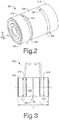
- Fig. 2 shows a perspective view on an exemplary bearing cartridge 200 that does not include an opening for receiving an axial thrust load pin.
- the cartridge 200 includes two annular wells 204, 204' positioned on an outer race 205 intermediate a center section 206 and respective ends of the cartridge 200.
- the cartridge 200 includes openings 207 and 207' that allow jet lubrication to enter and be directed at the balls of the cartridge 200. Additional openings are optionally included for lubricant flow.
- the wells 204, 204' are positioned adjacent to end sections 210,210', respectively.
- the end sections 210,210' of the outer race 205 have outer diameters that can define clearances with a housing and thereby allow for formation of lubricant films f1, f1', which may be substantially equal.
- Fig. 3 shows a side view of an exemplary cartridge 300 such as the cartridge 200 of Fig. 2 .
- the cartridge 300 includes an outer race 305 having an approximate length L, an approximate axial midpoint L m and including end sections 310, 310' having outer diameters D o 1, D o1 '.
- a drain or lubricant opening 309 is positioned at an axial position at or proximate to the midpoint L m .
- the cartridge 300 may include openings such as 207, 207' of the cartridge 200 of Fig. 2 .
- the lubricant opening 309 receives a pin to limit rotation of the outer race 305.
- the lubricant opening 309 may receive such a rotation limiting pin while still being capable of some radial movement.
- the cartridge 300 includes wells of axial width ⁇ w 1' ⁇ w 1' between a center section 306 and end sections 310, 310' with outer diameters D o 1 and D o 1'
- the well widths ⁇ w 1, ⁇ w 1' may be substantially equal.
- the outer sections 310, 310' may differ in axial width.
- the cartridge 300 may include an outer section 310 with outer diameter D o 1 that has an axial width less than the outer section 310' with outer diameter D o 1'.
- the exemplary cartridge 300 includes various parameters that may be used to achieve desired performance characteristics.
- the axial width and outer diameters of the various sections may be used to define radial clearances/film thicknesses and axial film length(s).
- judicious selection of thickness, length and number of squeeze films can act to achieve suitable reduction in radial freedom and optimized damping of rotor imbalance forces.
- Various examples capable of multiple squeeze film thicknesses are described further below with respect to Fig. 8 and Figs. 9A-B .
- Fig. 4 shows a cross-sectional diagram of an exemplary assembly 400 of a turbomachinery device.
- the assembly 400 includes a bearing cartridge 300 positioned in a housing 440 and located axially with aid of a plate 450.
- the plate 450 abuts a surface 446 of the housing 440.
- a pin 460 received by an opening 444 of the housing 440 aids in locating the cartridge 300 azimuthally with respect to the housing 440.
- the opening 444 optionally comprises a pin opening having an axis that intersects the central axis (e.g., x-axis) at an angle ⁇ , which is optionally non-orthogonal.
- the cartridge 300 is located axially with aid of a counterbore 442 of the housing 440 and the plate 450.
- the plate 450 and the counterbore 442 define an axial distance that is greater than the axial length of the outer race of the bearing cartridge 300.
- the axially locating mechanism allows the bearing cartridge to move radially.
- a clearance may be defined by the difference between the axial distance between a surface of the plate 450 and a surface of the counterbore 442 and the axial length of the outer race of the bearing cartridge 300. Adjustment to such a clearance may be possible via a fixation mechanism of the plate 450 (see, e.g., bolt 452) and/or other features (e.g., gaskets, spacers, etc.).
- Various features of the exemplary assembly 400 also act to directly distribute axial thrust loads to more than one component.
- the plate 450 can receive thrust loads and the counterbore 442 of the housing 440 can receive axial thrust loads from the bearing cartridge 300.
- the conventional assembly of Fig. 1B transmits axial thrust loads directly and solely to the pin 162.
- the exemplary assembly 400 can distribute axial thrust loads over greater surface area when compared to the pin 162 of the conventional assembly of Fig. 1B .
- the housing 440 includes an opening 444 that receives the pin 460 to aid in azimuthal location of the outer race of the bearing cartridge 300.
- a pin may be referred to as an anti-rotation pin or an azimuthal locating pin because it acts to locate azimuthally and limit rotation of an outer race of a bearing cartridge with respect to a housing.
- a lubricant drain opening 448 of the housing 440 allows for insertion of the pin 460 in the opening 444. In this manner, the lubricant drain opening 448 allows drainage of lubricant and insertion and/or adjustment of an anti-rotation pin. While a straight line shows access to the opening 444, access is optionally indirect (e.g., not along a straight line).
- Fig. 5 shows a cross-sectional top view of an exemplary housing 440 and a plate 450.
- the exemplary housing 440 includes a proximate recessed surface 446 and a distal counterbore 442.
- the proximate recessed surface 446 is optionally associated with a compressor side of a turbomachinery device and the distal counterbore 442 is optionally associated with a turbine side of a turbomachinery device.
- other arrangements are possible.
- the exemplary housing 440 includes an opening 444 set an angle to a central longitudinal housing axis (e.g., x-axis) that allows for insertion of a pin.
- a pin acts to azimuthally locate an outer race of a bearing cartridge in the exemplary housing 440.
- the exemplary housing 440 includes an attachment mechanism for the plate 450.
- threaded holes 445, 445' are provided that open along the surface 446.
- the holes 445, 445' receive bolts 452, 452', respectively.
- Washers 453, 453' are also shown in this example.
- Other attachment mechanisms may be used for attaching a plate to a housing.
- a substantially circular shaped plate is shown, other shapes are possible and may include one or more surfaces and/or one or more components that act to limit movement of an outer race of a bearing cartridge in the cylindrical bore of a housing in conjunction with a counterbore.
- An exemplary housing includes an attachment mechanism or mechanisms for a plate extend radially inward to a minimum radius less than the inner radius of a cylindrical bore wherein the plate acts to limit axial movement of a bearing cartridge in the cylindrical bore.
- Fig. 6 shows a front view of an exemplary assembly 600 that includes an exemplary housing 440 and an exemplary plate 450.
- the plate 450 fits in a recess of the housing 440.
- the plate 450 acts to define an axial distance along with a counterbore of the housing (not shown in Fig. 6 , see, e.g., Fig. 5 ).
- the axial distance acts to define a clearance or clearances between the outer race and the plate 450 and/or the counterbore of the housing 440.
- the exemplary plate 450 includes four openings 454, 454', 454", 454''' for use in securing the plate 450 to the housing 440.
- a bolt 452 or other device passes through the opening 454''' to secure the plate 450 to the housing 440.
- a washer 453 cooperates with the bolt 452 to secure the plate 450.
- the plate 450 includes an opening 456 that has an inner diameter less than the inner diameter of a substantially cylindrical bore of the housing 440.
- the opening 456 is substantially coaxial with the cylindrical bore of the housing 440.
- a counterbore 442 of the housing 440 has an inner diameter less than the inner diameter of the cylindrical bore of the housing 440.
- the counterbore 442 has an arc length less than 360 degrees.
- Exemplary counterbores may include one or more arc segments, protrusions, etc., that extend inwardly toward a longitudinal or center axis of the cylindrical bore to thereby limit movement of an outer race of a bearing cartridge in the cylindrical bore.
- Fig. 7 shows an exemplary assembly 700 that includes an exemplary plate 750.
- the plate 750 is a compressor backplate that tits into the recessed region of a housing 440, for example, at a surface 446.
- an attachment mechanism includes use of bolts 752, 752' to secure the plate 750 to the housing 440.
- the plate 750 extends radially inward past the surface 446 where it further extends past at least a portion of an outer race 305 of a bearing cartridge.
- the plate 750 includes an opening that has an inner dimension (e.g., a diameter, etc.) that is less than the outer diameter of the outer race 305.
- an exemplary plate may include a substantially circular opening with a diameter less than that of an outer race of a bearing cartridge
- various exemplary plates may include other shapes, protrusions, etc., that extend inwardly past an inner diameter of a substantially cylindrical bore of a housing to thereby limit axial movement of an outer race of a bearing cartridge.
- an exemplary plate optionally includes one or more protrusions that extend radially inward toward a central axis to limit movement of an outer race of a bearing cartridge. While not shown in Fig.
- the housing 440 optionally includes a counterbore to limit movement of the outer race 305, for example, where the plate 750 is positioned at a proximate end of a substantially cylindrical bore of a housing and the counterbore is positioned at distal end of the substantially cylindrical bore of the housing (see, e.g., the counterbore 442 of Fig. 5 ).
- the housing 440 of Fig. 7 includes a pin opening such as the opening 444 of Fig. 5 . While such an opening is sometimes referred to herein as a "pin" opening, the term pin may optionally refer to various mechanisms such as screws, bolts, etc., that act to limit rotation of an outer race of a bearing cartridge.
- Fig. 8 shows a cross-sectional diagram of an exemplary bearing cartridge 800 that allows for multiple films of optionally different thicknesses.
- the cartridge 800 includes a center section 806, intermediate sections 810, 810' and outer sections 812, 812'.
- the bearing also includes lubricant passages 807, 807' and 809.
- An enlargement shows various wells (e.g., wells, grind reliefs, etc.) and/or transitions from a first outer diameter to a second outer diameter.
- a wall 866 of a housing or journal having an inner diameter acts to define clearances and film thicknesses f1, f2.
- wells have curvilinear cross-section; in a second scenario 802, wells have substantially polygonal cross-section; and in a third scenario 803, a step in outer diameter exists between a thick film region f1 and a thinner film region f2.
- the scenarios 801, 802, 803 are exemplary as others may be used to create clearances that form multiple film thicknesses.
- a housing or journal may act to define clearances that form multiple film thicknesses between the housing and one or more outer diameters of a bearing cartridge.
- an exemplary housing may include two or more inner diameters that act to define more than one annular clearance with a bearing cartridge and a counterbore to help axially locate the bearing cartridge and/or an opening for receiving a pin to help azimuthally locate an outer race of the bearing cartridge.
- Fig. 9A shows a cross-sectional, side view of an exemplary housing 940
- Fig. 9B shows a cross-sectional top view of the exemplary bearing housing 940.
- the exemplary housing 940 can house a bearing cartridge and act to define clearances between an outer surface of the bearing cartridge and an inner wall of the housing 940 wherein the clearances act to form various films that can be aimed at reduction of unwanted excessive radial clearance and/or optimized damping of rotor imbalance forces.
- the exemplary housing 940 includes a counterbore 942, an opening 944 and a surface 946 substantially perpendicular to a central axis (e.g., x-axis).
- the opening 944 optionally comprises a pin opening having an axis that intersects the central axis at an angle ⁇ , which is optionally non-orthogonal.
- the surface 946 and the counterbore 942 may define a distance that in combination with a bearing cartridge acts to define an axial clearance.
- a plate (see, e.g., the plate 450 of Fig. 6 ) cooperates with the surface 946 to define a proximate end of a bearing cartridge chamber while the counterbore 942 defines a distal end of the bearing cartridge chamber.
- the bearing cartridge chamber includes an inner surface 966 that has a first inner diameter and an inner surface 967 that has a second inner diameter wherein the first inner diameter exceeds the second inner diameter.
- a bearing cartridge that includes an outer surface having an outer diameter may act to define annular clearances with the first and second inner surfaces 966, 967 when positioned in the housing to form an assembly.
- Various exemplary devices, methods, systems, arrangements, etc., described herein pertain to formation and use of multiple film thicknesses.
- one film has damping characteristics and another film has characteristics that minimize excessive radial freedom and play.
- An exemplary bearing cartridge includes an inner film to outer film ratio of approximately 1:2, i.e., the inner film being approximately twice the thickness of the outer film.
- Such an exemplary bearing cartridge may be suitable for use in a commercially available GARRETT® GTA47-55R turbomachinery device (Torranoe, California).
- a sufficiently thick film can act to reduce noise and vibration and loading through the system; whereas a thinner film can reduce slop or play in the system (e.g., rotor play, etc.).
- a thinner film may also allow for reduction in wheel to housing clearances in a turbocharger system, which can act to reduce undesirable secondary aerodynamic flows that would cause reduced compressor and turbine stage thermodynamic efficiencies.
- Various examples include one or more thinner clearance regions proximate to an outer end(s) of a bearing cartridge.
- a pair of thinner clearance regions proximate to outer ends of a bearing cartridge may limit pivot when compared to a thinner clearance region(s) positioned proximate to or at a center section.
Landscapes
- Engineering & Computer Science (AREA)
- General Engineering & Computer Science (AREA)
- Mechanical Engineering (AREA)
- Supercharger (AREA)
- Rolling Contact Bearings (AREA)
- Mounting Of Bearings Or Others (AREA)
- Support Of The Bearing (AREA)
- Structures Of Non-Positive Displacement Pumps (AREA)
Claims (9)
- Anordnung (400, 600, 700) für einen Turbolader, umfassend:eine Lagerpatrone (200, 300, 800), die eine äußere Laufbahn (205, 305) mit einem Außendurchmesser (Do1, Do1') umfasst;ein Gehäuse (440, 940), das umfassteine im Wesentlichen zylindrische Bohrung mit einer Längsachse (x), einem proximalen Ende, einem distalen Ende und einem Innendurchmesser, der den Außendurchmesser (Do1, Do1') der äußeren Laufbahn (205, 305) der Lagerpatrone (200, 300, 800) übersteigt,eine Gegenbohrung (442, 942), die im Wesentlichen koaxial zu der zylindrischen Bohrung an dem distalen Ende der zylindrischen Bohrung ist und einen Innendurchmesser aufweist, der kleiner als der Außendurchmesser (Do1, Do1') der äußeren Laufbahn (205, 305) der Lagerpatrone (200, 300, 800) ist, wobei die Gegenbohrung (442, 942) eine axiale Bewegung der äußeren Laufbahn (205, 305) an dem distalen Ende der zylindrischen Bohrung begrenzt,eine Schmiermittelablauföffnung (448), undeine Stiftöffnung (444, 944), die über die Schmiermittelablauföffnung (448) zugänglich ist;eine Platte (450, 750), die im Wesentlichen rechtwinklig zu der Längsachse (x) der zylindrischen Bohrung an dem proximalen Ende der zylindrischen Bohrung positioniert ist, wobei die Platte (450, 750) eine axiale Bewegung der äußeren Laufbahn (205, 305) an dem proximalen Ende der zylindrischen Bohrung begrenzt; undeinen Stift (460), der in der Stiftöffnung (444, 944) des Gehäuses (440, 940) über die Schmiermittelablauföffnung (448) positioniert ist, wobei der Stift (460) eine Drehung der äußeren Laufbahn (205, 305) begrenzt.
- Anordnung nach Anspruch 1, wobei die Stiftöffnungsachse die Längsachse (x) der zylindrischen Bohrung in einem nicht rechtwinkligen Winkel (φ) schneidet.
- Anordnung nach Anspruch 1, wobei die äußere Laufbahn eine Ablauföffnung (309, 809) zum Aufnehmen des Stifts (460) umfasst.
- Anordnung nach Anspruch 1, ferner umfassend Spielräume zwischen der äußeren Laufbahn (205, 305) und der Bohrung des Gehäuses, um Schmiermitteldruckfilme (f1, f1', f2) auszubilden.
- Anordnung nach Anspruch 4, wobei die ausgebildeten Schmiermitteldruckfilme mehrere Druckfilmdicken (f1, f2) umfassen.
- Anordnung nach Anspruch 5, ferner umfassend ein Schmiermittel, das Folgendes ausbildet:in einem ringförmigen Spielraum zwischen der äußeren Laufbahn und der im Wesentlichen zylindrischen Bohrung des Gehäuses, einen ersten dicken Schmiermitteldruckfilm (f1), der Schwingungen der Lagerpatrone (800) dämpft; undin einem ringförmigen Spielraum zwischen der äußeren Laufbahn und der im Wesentlichen zylindrischen Bohrung des Gehäuses, einen zweiten, dünneren Schmiermitteldruckfilm (f2), der ein Radialspiel der Lagerpatrone (800) begrenzt.
- Anordnung nach Anspruch 6, wobei die Dicke des ersten Schmiermitteldruckfilms (f1) um einen Faktor von ungefähr 2 dicker ist als die Dicke des zweiten Schmiermitteldruckfilms (f2).
- Anordnung nach Anspruch 6, wobei das Schmiermittel den zweiten, dünneren Schmiermitteldruckfilm (f2) proximal zu einem äußeren Ende(n) einer Lagerpatrone (800) ausbildet.
- Anordnung nach Anspruch 6, ferner umfassend, dass das Schmiermittel in einem Paar von dünneren Spielraumbereichen zweite Schmiermitteldruckfilme (f2) ausbildet, die ein Radialspiel der Lagerpatrone (800) in der Bohrung begrenzen.
Applications Claiming Priority (3)
| Application Number | Priority Date | Filing Date | Title |
|---|---|---|---|
| US10/879,253 US7214037B2 (en) | 2004-06-28 | 2004-06-28 | Retention of ball bearing cartridge for turbomachinery |
| PCT/US2005/022721 WO2006004654A1 (en) | 2004-06-28 | 2005-06-28 | Rotational anx axial retention of ball bearing cartridge in the housing of a turbomachine |
| EP05763246A EP1761683B1 (de) | 2004-06-28 | 2005-06-28 | Verfahren zum axialen und drehsicheren Festlegen eines Kugellagereinsatzes in einem Turbomaschinengehäuse |
Related Parent Applications (2)
| Application Number | Title | Priority Date | Filing Date |
|---|---|---|---|
| EP05763246A Division EP1761683B1 (de) | 2004-06-28 | 2005-06-28 | Verfahren zum axialen und drehsicheren Festlegen eines Kugellagereinsatzes in einem Turbomaschinengehäuse |
| EP05763246.5 Division | 2005-06-28 |
Publications (3)
| Publication Number | Publication Date |
|---|---|
| EP2372178A2 EP2372178A2 (de) | 2011-10-05 |
| EP2372178A3 EP2372178A3 (de) | 2011-11-09 |
| EP2372178B1 true EP2372178B1 (de) | 2020-08-12 |
Family
ID=35355799
Family Applications (3)
| Application Number | Title | Priority Date | Filing Date |
|---|---|---|---|
| EP11166456.1A Expired - Lifetime EP2365227B1 (de) | 2004-06-28 | 2005-06-28 | Verdreh- und Verschiebesicherung einer zweireihigen Kugellageranordnung im Gehäuse einer Turbomaschine mit flüssigkeitsgefülltem Dämpfungsspalt |
| EP05763246A Expired - Lifetime EP1761683B1 (de) | 2004-06-28 | 2005-06-28 | Verfahren zum axialen und drehsicheren Festlegen eines Kugellagereinsatzes in einem Turbomaschinengehäuse |
| EP11166455.3A Expired - Lifetime EP2372178B1 (de) | 2004-06-28 | 2005-06-28 | Verdreh- und verschiebesicherung einer zweireihigen kugellageranordnung im gehäuse einer turbomaschine mit flüssigkeitsgefülltem dämpfungsspalt |
Family Applications Before (2)
| Application Number | Title | Priority Date | Filing Date |
|---|---|---|---|
| EP11166456.1A Expired - Lifetime EP2365227B1 (de) | 2004-06-28 | 2005-06-28 | Verdreh- und Verschiebesicherung einer zweireihigen Kugellageranordnung im Gehäuse einer Turbomaschine mit flüssigkeitsgefülltem Dämpfungsspalt |
| EP05763246A Expired - Lifetime EP1761683B1 (de) | 2004-06-28 | 2005-06-28 | Verfahren zum axialen und drehsicheren Festlegen eines Kugellagereinsatzes in einem Turbomaschinengehäuse |
Country Status (4)
| Country | Link |
|---|---|
| US (4) | US7214037B2 (de) |
| EP (3) | EP2365227B1 (de) |
| CN (1) | CN101014753A (de) |
| WO (1) | WO2006004654A1 (de) |
Families Citing this family (105)
| Publication number | Priority date | Publication date | Assignee | Title |
|---|---|---|---|---|
| US7214037B2 (en) * | 2004-06-28 | 2007-05-08 | Honeywell International, Inc. | Retention of ball bearing cartridge for turbomachinery |
| US7104693B2 (en) * | 2004-06-28 | 2006-09-12 | Honeywell International, Inc. | Multi-thickness film layer bearing cartridge and housing |
| US7909588B2 (en) * | 2004-07-12 | 2011-03-22 | Cameron International Corporation | Modular rotor assembly |
| US20070110351A1 (en) * | 2005-11-16 | 2007-05-17 | Honeywell International, Inc. | Centering mechanisms for turbocharger bearings |
| US8503431B2 (en) | 2006-08-25 | 2013-08-06 | Wireless Wonders Ltd. | Mobile phone related indirect communication system and method |
| US9270799B2 (en) | 2006-08-25 | 2016-02-23 | Wireless Wonders Ltd. | Using indirect communication to provide a solution to use international dialing convention and incorporating phone numbers for non-phone devices |
| US8118570B2 (en) * | 2007-10-31 | 2012-02-21 | Honeywell International Inc. | Anisotropic bearing supports for turbochargers |
| JP5157501B2 (ja) * | 2008-02-06 | 2013-03-06 | 株式会社Ihi | 冷凍機 |
| JP5075000B2 (ja) * | 2008-04-28 | 2012-11-14 | トヨタ自動車株式会社 | 過給機の軸受装置 |
| US8186922B2 (en) * | 2008-06-03 | 2012-05-29 | Honeywell International Inc. | Multi-piece locating pin |
| PL2894352T3 (pl) * | 2008-06-13 | 2019-05-31 | Weir Minerals Australia Ltd | Regulowane wyłożenie boczne do pompy |
| US8186947B2 (en) * | 2008-09-16 | 2012-05-29 | Honeywell International Inc. | Conical pin to maintain bearing system |
| US8118544B2 (en) * | 2009-01-07 | 2012-02-21 | Honeywell International Inc. | Bearing and retention mechanisms |
| IT1393309B1 (it) * | 2009-03-18 | 2012-04-20 | Turboden Srl | Perfezionamenti ad una turbina per espansione di gas/vapore |
| CN102395770B (zh) * | 2009-04-20 | 2014-07-30 | 博格华纳公司 | 用于滚动元件轴承套筒的抗转动方法 |
| KR20120014901A (ko) | 2009-04-20 | 2012-02-20 | 보르그워너 인코퍼레이티드 | 롤링 요소 베어링 카트리지를 위한 절연 및 감쇠 슬리브 |
| DE112010001913T5 (de) | 2009-05-07 | 2012-06-14 | Borgwarner Inc. | Federclipverfahren zur Verdrehsicherung und Schittbegrenzung einer Wälzelementlagerpatrone |
| BRPI1013571A2 (pt) | 2009-05-07 | 2016-04-12 | Borgwarner Inc | método de grampo deslizante para restrição de antirrotação e impulso de um cartucho de mancal de elemento de rolamento |
| US8496452B2 (en) * | 2009-08-26 | 2013-07-30 | Honeywell International Inc. | Bearing spacer and housing |
| US8961128B2 (en) * | 2009-08-26 | 2015-02-24 | Honeywell International Inc. | Bearing spacer and housing |
| DE102009053101B4 (de) * | 2009-11-13 | 2016-02-25 | Continental Automotive Gmbh | Turbolader mit einem Turboladergehäuse und einer Aufnahmeeinrichtung für das Laufzeug des Turboladers |
| US9140185B2 (en) * | 2009-11-24 | 2015-09-22 | Honeywell International Inc. | Locating mechanism for turbocharger bearing |
| DE102010005491A1 (de) * | 2010-01-23 | 2011-07-28 | Bosch Mahle Turbo Systems GmbH & Co. KG, 70376 | Abgasturbolader |
| US20110236193A1 (en) * | 2010-03-25 | 2011-09-29 | Schaeffler Technologies Gmbh & Co. Kg | Turbocharger bearing lubrication |
| WO2011143079A2 (en) * | 2010-05-14 | 2011-11-17 | Borgwarner Inc. | Exhaust-gas turbocharger |
| DE102010035665A1 (de) | 2010-08-27 | 2012-03-01 | Schaeffler Technologies Gmbh & Co. Kg | Lagerung |
| US8449199B2 (en) | 2010-10-27 | 2013-05-28 | Precision Turbo & Engine Rebuilders, Inc. | Bearing retention assembly for and method of assembling turbochargers |
| KR101841239B1 (ko) | 2010-10-28 | 2018-05-04 | 보르그워너 인코퍼레이티드 | 축방향 추력 감쇠 및 회전방지 조립체들을 구비한 롤링 요소 베어링 카트리지 |
| DE102010054939A1 (de) * | 2010-12-17 | 2012-06-21 | Schaeffler Technologies Gmbh & Co. Kg | Lageranordnung für einen Turbolader und Turbolader |
| DE102010054926A1 (de) | 2010-12-17 | 2012-06-21 | Schaeffler Technologies Gmbh & Co. Kg | Lagereinheit für einen Turbolader |
| DE102010054937A1 (de) | 2010-12-17 | 2012-06-21 | Schaeffler Technologies Gmbh & Co. Kg | Lageranordnung für einen Turbolader |
| DE102010054905A1 (de) * | 2010-12-17 | 2012-06-21 | Schaeffler Technologies Gmbh & Co. Kg | Lagereinheit für einen Turbolader |
| DE102011008905B4 (de) * | 2011-01-19 | 2023-11-16 | Minebea Mitsumi Inc. | Lagereinheit für Turbolader-Spindel-Einheiten |
| JP5522113B2 (ja) * | 2011-04-13 | 2014-06-18 | 株式会社豊田自動織機 | ターボチャージャ |
| DE102011007250A1 (de) * | 2011-04-13 | 2012-10-18 | Schaeffler Technologies AG & Co. KG | Turboladerkartusche mit gleitlager gestütztem Wälzlager |
| EP2698504A1 (de) * | 2011-06-17 | 2014-02-19 | Aktiebolaget SKF | Turbolader, insbesondere für einen Verbrennungsmotor |
| US8591114B2 (en) * | 2011-06-27 | 2013-11-26 | Wind Simplicity Inc. | Spindle |
| DE102011078427A1 (de) * | 2011-06-30 | 2013-01-03 | Schaeffler Technologies AG & Co. KG | Einpresskraft optimiertes Wälzlager |
| JP5535992B2 (ja) | 2011-07-15 | 2014-07-02 | 三菱重工業株式会社 | 電動過給圧縮機、その組立方法及び内燃機関 |
| CN102418569B (zh) * | 2011-08-19 | 2015-03-04 | 中国兵器工业集团第七○研究所 | 可拆分的基于双单列轴承构成的整体式球轴承涡轮增压器 |
| DE102011081419A1 (de) * | 2011-08-23 | 2013-02-28 | Schaeffler Technologies AG & Co. KG | Quetschöldämpfer |
| US8911202B2 (en) * | 2011-09-20 | 2014-12-16 | Honeywell International Inc. | Turbocharger rotating assembly |
| US8727629B2 (en) * | 2011-11-01 | 2014-05-20 | General Electric Company | Series bearing support apparatus for a gas turbine engine |
| US9051848B2 (en) | 2011-11-08 | 2015-06-09 | Honeywell International Inc. | Turbocharger housing and bearing locating pin |
| US9482278B2 (en) | 2011-12-14 | 2016-11-01 | Precision Turbo & Engine Rebuilders, Inc. | Cost effective high thrust capacity turbocharger assembly |
| DE112013000435T5 (de) * | 2012-01-26 | 2014-09-18 | Borgwarner Inc. | Abgasturbolader |
| DE102012206556B4 (de) * | 2012-04-20 | 2015-10-29 | Schaeffler Technologies AG & Co. KG | Lagereinheit für einen Turbolader |
| EP2657553B1 (de) * | 2012-04-23 | 2014-12-31 | Aktiebolaget SKF | Lager, Lagerbaugruppe mit solch einem Lager und Turbolader mit solch einer Lagerbaugruppe |
| US10001028B2 (en) | 2012-04-23 | 2018-06-19 | General Electric Company | Dual spring bearing support housing |
| JP6236440B2 (ja) * | 2012-06-25 | 2017-11-22 | ボーグワーナー インコーポレーテッド | 排気ガスターボチャージャ |
| KR102031227B1 (ko) * | 2012-06-25 | 2019-10-11 | 보르그워너 인코퍼레이티드 | 배기가스 터보차저 |
| US9121304B2 (en) | 2012-09-11 | 2015-09-01 | Honeywell International Inc. | Outer race locating washer |
| US9970448B2 (en) * | 2012-11-12 | 2018-05-15 | Borgwarner Inc. | Swirl inducing bearing housing spacer and core |
| GB201307674D0 (en) | 2013-04-29 | 2013-06-12 | Cummins Ltd | Turbomachine With Axial Stop Member |
| US9963998B2 (en) * | 2013-06-18 | 2018-05-08 | Honeywell International Inc. | Assembly with bearings and spacer |
| USD718121S1 (en) * | 2013-09-30 | 2014-11-25 | Bitspower International Co., Ltd. | Tube connector |
| DE102014201081A1 (de) * | 2014-01-22 | 2015-07-23 | Bayerische Motoren Werke Aktiengesellschaft | Abgasturbolader |
| US9431875B2 (en) * | 2014-03-28 | 2016-08-30 | Scaled Power Corp. | Gas turbine generator with a pre-combustion power turbine |
| DE112015001775B4 (de) | 2014-04-11 | 2020-07-09 | Borgwarner Inc. | Mehrteiliges Radiallager |
| CN105332115B (zh) * | 2014-05-30 | 2020-07-31 | 舍弗勒技术股份两合公司 | 轴承组件 |
| DE102014212155B4 (de) * | 2014-06-25 | 2024-09-19 | Vitesco Technologies GmbH | Lagervorrichtung für eine Welle einer Turboladereinrichtung |
| DE102014214783A1 (de) | 2014-07-28 | 2016-01-28 | Bosch Mahle Turbo Systems Gmbh & Co. Kg | Ladeeinrichtung |
| DE102014217164B4 (de) * | 2014-08-28 | 2016-09-01 | Schaeffler Technologies AG & Co. KG | Läufer für einen Abgasturbolader |
| US9874244B2 (en) * | 2015-02-13 | 2018-01-23 | United Technologies Corporation | Bearing with integrated oil delivery system |
| US9181955B1 (en) * | 2015-02-18 | 2015-11-10 | Borgwarner Inc. | Method for reducing aero clearances with a ball bearing turbocharger |
| US9739238B2 (en) * | 2015-03-09 | 2017-08-22 | Caterpillar Inc. | Turbocharger and method |
| US9683520B2 (en) * | 2015-03-09 | 2017-06-20 | Caterpillar Inc. | Turbocharger and method |
| US9822700B2 (en) | 2015-03-09 | 2017-11-21 | Caterpillar Inc. | Turbocharger with oil containment arrangement |
| US10066639B2 (en) | 2015-03-09 | 2018-09-04 | Caterpillar Inc. | Compressor assembly having a vaneless space |
| US9732633B2 (en) | 2015-03-09 | 2017-08-15 | Caterpillar Inc. | Turbocharger turbine assembly |
| US9915172B2 (en) | 2015-03-09 | 2018-03-13 | Caterpillar Inc. | Turbocharger with bearing piloted compressor wheel |
| US20160281647A1 (en) * | 2015-03-09 | 2016-09-29 | Caterpillar Inc. | Turbocharger and Method |
| US9879594B2 (en) | 2015-03-09 | 2018-01-30 | Caterpillar Inc. | Turbocharger turbine nozzle and containment structure |
| US9650913B2 (en) | 2015-03-09 | 2017-05-16 | Caterpillar Inc. | Turbocharger turbine containment structure |
| US9903225B2 (en) | 2015-03-09 | 2018-02-27 | Caterpillar Inc. | Turbocharger with low carbon steel shaft |
| US10006341B2 (en) | 2015-03-09 | 2018-06-26 | Caterpillar Inc. | Compressor assembly having a diffuser ring with tabs |
| US9810238B2 (en) | 2015-03-09 | 2017-11-07 | Caterpillar Inc. | Turbocharger with turbine shroud |
| US9638138B2 (en) * | 2015-03-09 | 2017-05-02 | Caterpillar Inc. | Turbocharger and method |
| US9752536B2 (en) * | 2015-03-09 | 2017-09-05 | Caterpillar Inc. | Turbocharger and method |
| US9890788B2 (en) | 2015-03-09 | 2018-02-13 | Caterpillar Inc. | Turbocharger and method |
| US9777747B2 (en) | 2015-03-09 | 2017-10-03 | Caterpillar Inc. | Turbocharger with dual-use mounting holes |
| US10208623B2 (en) | 2015-04-12 | 2019-02-19 | Garrett Transportation I Inc. | Turbocharger bearing assembly |
| US9976476B2 (en) | 2015-04-12 | 2018-05-22 | Honeywell International Inc. | Turbocharger bearing assembly |
| US9695708B2 (en) | 2015-04-12 | 2017-07-04 | Honeywell International Inc. | Turbocharger spring assembly |
| US9745992B2 (en) | 2015-08-30 | 2017-08-29 | Honeywell International Inc. | Turbocharger bearing damper assembly |
| US11193385B2 (en) | 2016-04-18 | 2021-12-07 | General Electric Company | Gas bearing seal |
| US10001166B2 (en) | 2016-04-18 | 2018-06-19 | General Electric Company | Gas distribution labyrinth for bearing pad |
| US9746029B1 (en) | 2016-04-18 | 2017-08-29 | General Electric Company | Bearing |
| US9951811B2 (en) | 2016-04-18 | 2018-04-24 | General Electric Company | Bearing |
| US10036279B2 (en) | 2016-04-18 | 2018-07-31 | General Electric Company | Thrust bearing |
| US10066505B2 (en) | 2016-04-18 | 2018-09-04 | General Electric Company | Fluid-filled damper for gas bearing assembly |
| US10914195B2 (en) | 2016-04-18 | 2021-02-09 | General Electric Company | Rotary machine with gas bearings |
| JP6678086B2 (ja) * | 2016-08-12 | 2020-04-08 | ミネベアミツミ株式会社 | ターボチャージャー用転がり軸受および回り止め機構 |
| US10330002B2 (en) * | 2016-12-12 | 2019-06-25 | Garrett Transportation I Inc. | Turbocharger assembly |
| US10677253B2 (en) * | 2016-12-12 | 2020-06-09 | Garrett Transportation I Inc. | Turbocharger assembly |
| DE102016226036A1 (de) * | 2016-12-22 | 2018-06-28 | Bosch Mahle Turbo Systems Gmbh & Co. Kg | Ladeeinrichtung |
| DE102017218053B4 (de) | 2017-10-10 | 2019-06-19 | Continental Automotive Gmbh | Turboladereinrichtung und Verfahren zu deren Montage |
| US11131242B2 (en) * | 2017-11-24 | 2021-09-28 | Brp-Rotax Gmbh & Co. Kg | Turbocharger for an internal combustion engine |
| CN108180226B (zh) * | 2017-12-27 | 2019-06-07 | 重庆市丰蕙达金属锻造有限公司 | 一种防尘轴承座 |
| US11698078B2 (en) | 2018-03-30 | 2023-07-11 | Mitsubishi Heavy Industries Engine & Turbocharger, Ltd. | Rotating machine and turbocharger |
| US11067131B2 (en) * | 2018-06-07 | 2021-07-20 | Borg Warner Inc. | Anti-rotation assembly and bearing housing assembly including the same |
| US10935080B2 (en) * | 2019-03-14 | 2021-03-02 | Raytheon Technologies Corporation | Extended housing sleeve with stiffening ring feature |
| US10954996B2 (en) * | 2019-06-27 | 2021-03-23 | GM Global Technology Operations LLC | Turbocharger bearing |
| JP7593046B2 (ja) | 2020-10-16 | 2024-12-03 | 日本精工株式会社 | センサユニット |
| CN116928131B (zh) * | 2023-06-14 | 2024-06-07 | 浙江颐顿机电有限公司 | 一种耐腐蚀自润滑水泵轴承 |
Family Cites Families (38)
| Publication number | Priority date | Publication date | Assignee | Title |
|---|---|---|---|---|
| US1691015A (en) * | 1926-12-11 | 1928-11-06 | Fafnir Bearing Co | Lubricating means for antifriction bearings |
| US2194328A (en) * | 1938-02-21 | 1940-03-19 | Monad Corp | Bearing assembly |
| US2441294A (en) * | 1945-01-01 | 1948-05-11 | Julius E Shafer | Bearing assembly |
| US2451115A (en) * | 1945-02-05 | 1948-10-12 | Hoover Ball & Bearing Co | Pillow block bearing |
| US2690683A (en) * | 1953-02-26 | 1954-10-05 | Roller Gear Company Inc | Ball bearing screw |
| US3195965A (en) * | 1961-10-25 | 1965-07-20 | Fafnir Bearing Co | Lubricating means for an antifriction bearing |
| DE1425025A1 (de) * | 1963-06-26 | 1968-12-05 | Geraetebau Eberspaecher Ohg | Elastische Wellenabstuetzung |
| US3311429A (en) * | 1964-08-21 | 1967-03-28 | Int Harvester Co | Self-aligning bearing assembly |
| US3456992A (en) * | 1967-04-07 | 1969-07-22 | Curtiss Wright Corp | Vibration damping device |
| JPS4978048A (de) | 1972-12-06 | 1974-07-27 | ||
| US4235484A (en) * | 1979-02-22 | 1980-11-25 | Wallace Murray Corporation | Bearing carrier with integral lubricating sealing features |
| US4240678A (en) * | 1979-02-22 | 1980-12-23 | Wallace Murray Corporation | Non-rotating fluid damped combination thrust and journal bearing |
| GB2107002A (en) | 1981-10-02 | 1983-04-20 | Rolls Royce | Journal bearing |
| DE3531313C3 (de) * | 1984-09-03 | 1995-04-20 | Ishikawajima Harima Heavy Ind | Lagervorrichtung in einem Turbolader |
| US4713146A (en) * | 1985-01-14 | 1987-12-15 | Rockwell International Corporation | Drive shaft assembly |
| JPH028102Y2 (de) * | 1985-02-07 | 1990-02-27 | ||
| US4652219A (en) * | 1985-05-30 | 1987-03-24 | Teledyne Industries, Inc. | Turbocharger having a preloaded bearing assembly |
| US4671681A (en) * | 1986-06-30 | 1987-06-09 | Emerson Electric Co. | Grease pressure limiter and flow control for bearings |
| JPH082441Y2 (ja) * | 1987-06-01 | 1996-01-29 | トヨタ自動車株式会社 | 圧縮比切換装置 |
| JPH0540273Y2 (de) * | 1988-04-26 | 1993-10-13 | ||
| JPH0830501B2 (ja) * | 1988-06-07 | 1996-03-27 | 日産自動車株式会社 | 軸受固定装置 |
| JPH079247B2 (ja) * | 1988-06-07 | 1995-02-01 | 日産自動車株式会社 | 転がり軸受の制振装置 |
| US4887479A (en) * | 1988-07-26 | 1989-12-19 | Sundstrand Corporation | Ball cage for helical ballspline |
| DE3825326A1 (de) * | 1988-07-26 | 1990-02-01 | Kugelfischer G Schaefer & Co | Waelzlager fuer abgasturbolader |
| US5145334A (en) * | 1989-12-12 | 1992-09-08 | Allied-Signal Inc. | Turbocharger bearing retention and lubrication system |
| US5076766A (en) | 1989-12-12 | 1991-12-31 | Allied-Signal Inc. | Turbocharger bearing retention and lubrication system |
| US5890881A (en) * | 1996-11-27 | 1999-04-06 | Alliedsignal Inc. | Pressure balanced turbocharger rotating seal |
| US6017184A (en) * | 1997-08-06 | 2000-01-25 | Allied Signal Inc. | Turbocharger integrated bearing system |
| US6220829B1 (en) * | 1998-10-05 | 2001-04-24 | Glenn F. Thompson | Turbocharger rotor with low-cost ball bearing |
| US6290397B1 (en) * | 1998-11-30 | 2001-09-18 | The Timken Company | Ooze flow bearing |
| GB9917232D0 (en) | 1999-07-23 | 1999-09-22 | Notetry Ltd | Method of operating a floor cleaning device |
| DE60016976T2 (de) | 2000-03-13 | 2005-12-15 | Alliedsignal Inc. | Lagereinheit für den rotor eines turboladers |
| JP2001303964A (ja) * | 2000-04-24 | 2001-10-31 | Ishikawajima Harima Heavy Ind Co Ltd | ターボチャージャの軸受構造 |
| EP1174629A1 (de) | 2000-06-30 | 2002-01-23 | Techspace Aero S.A. | Dichtung eines in ein Wälzlager integrierten Quetschfilmdämpfers |
| EP1167788A1 (de) * | 2000-06-30 | 2002-01-02 | Techspace Aero S.A. | Dichtung eines in ein Wälzlager integrierten Quetschfilmdämpfers |
| US20020136473A1 (en) * | 2001-03-23 | 2002-09-26 | Mollmann Daniel Edward | Squeeze film damper bearing for gas turbine engine |
| US7104693B2 (en) * | 2004-06-28 | 2006-09-12 | Honeywell International, Inc. | Multi-thickness film layer bearing cartridge and housing |
| US7214037B2 (en) * | 2004-06-28 | 2007-05-08 | Honeywell International, Inc. | Retention of ball bearing cartridge for turbomachinery |
-
2004
- 2004-06-28 US US10/879,253 patent/US7214037B2/en not_active Expired - Lifetime
-
2005
- 2005-06-28 EP EP11166456.1A patent/EP2365227B1/de not_active Expired - Lifetime
- 2005-06-28 EP EP05763246A patent/EP1761683B1/de not_active Expired - Lifetime
- 2005-06-28 WO PCT/US2005/022721 patent/WO2006004654A1/en not_active Ceased
- 2005-06-28 EP EP11166455.3A patent/EP2372178B1/de not_active Expired - Lifetime
- 2005-06-28 CN CNA2005800284695A patent/CN101014753A/zh active Pending
-
2007
- 2007-03-08 US US11/683,615 patent/US7461979B2/en not_active Expired - Lifetime
-
2008
- 2008-11-25 US US12/323,295 patent/US7987599B2/en not_active Expired - Lifetime
-
2011
- 2011-07-12 US US13/180,696 patent/US8454242B2/en not_active Expired - Lifetime
Non-Patent Citations (1)
| Title |
|---|
| None * |
Also Published As
| Publication number | Publication date |
|---|---|
| US20070147721A1 (en) | 2007-06-28 |
| US20120177314A1 (en) | 2012-07-12 |
| US8454242B2 (en) | 2013-06-04 |
| WO2006004654A1 (en) | 2006-01-12 |
| EP1761683B1 (de) | 2013-03-06 |
| EP2372178A2 (de) | 2011-10-05 |
| EP2365227A2 (de) | 2011-09-14 |
| US7461979B2 (en) | 2008-12-09 |
| US7987599B2 (en) | 2011-08-02 |
| CN101014753A (zh) | 2007-08-08 |
| EP2372178A3 (de) | 2011-11-09 |
| US7214037B2 (en) | 2007-05-08 |
| EP2365227A3 (de) | 2012-03-07 |
| EP1761683A1 (de) | 2007-03-14 |
| EP2365227B1 (de) | 2021-03-03 |
| US20090071003A1 (en) | 2009-03-19 |
| US20050287018A1 (en) | 2005-12-29 |
Similar Documents
| Publication | Publication Date | Title |
|---|---|---|
| EP1761683B1 (de) | Verfahren zum axialen und drehsicheren Festlegen eines Kugellagereinsatzes in einem Turbomaschinengehäuse | |
| US7419304B2 (en) | Multi-thickness film layer bearing cartridge and housing | |
| US8449190B2 (en) | Centering mechanisms for turbocharger bearings | |
| JP7597504B2 (ja) | 一体型スクィーズフィルムダンパを備えた単列玉軸受 | |
| EP2208903B1 (de) | Lager- und Rückhaltemechanismen | |
| WO2007005478A1 (en) | Turbocharger bearing and associated components | |
| EP3597946A1 (de) | Axial beabstandeter dämpfer | |
| KR20190111064A (ko) | 유체 역학적으로 축선 방향으로 고정부를 갖는 플레인 베어링 | |
| KR101522503B1 (ko) | 원호형 비대칭 제거부가 형성된 플랜지 일체형 베어링 |
Legal Events
| Date | Code | Title | Description |
|---|---|---|---|
| PUAI | Public reference made under article 153(3) epc to a published international application that has entered the european phase |
Free format text: ORIGINAL CODE: 0009012 |
|
| AC | Divisional application: reference to earlier application |
Ref document number: 1761683 Country of ref document: EP Kind code of ref document: P |
|
| AK | Designated contracting states |
Kind code of ref document: A2 Designated state(s): AT BE BG CH CY CZ DE DK EE ES FI FR GB GR HU IE IS IT LI LT LU MC NL PL PT RO SE SI SK TR |
|
| PUAL | Search report despatched |
Free format text: ORIGINAL CODE: 0009013 |
|
| AK | Designated contracting states |
Kind code of ref document: A3 Designated state(s): AT BE BG CH CY CZ DE DK EE ES FI FR GB GR HU IE IS IT LI LT LU MC NL PL PT RO SE SI SK TR |
|
| RIC1 | Information provided on ipc code assigned before grant |
Ipc: F16F 15/023 20060101ALI20110930BHEP Ipc: F16C 35/067 20060101ALI20110930BHEP Ipc: F16C 27/04 20060101ALI20110930BHEP Ipc: F16C 19/18 20060101ALI20110930BHEP Ipc: F01D 25/16 20060101AFI20110930BHEP Ipc: F02C 6/12 20060101ALI20110930BHEP |
|
| 17P | Request for examination filed |
Effective date: 20120508 |
|
| RAP1 | Party data changed (applicant data changed or rights of an application transferred) |
Owner name: HONEYWELL INTERNATIONAL INC. |
|
| RAP1 | Party data changed (applicant data changed or rights of an application transferred) |
Owner name: GARRETT TRANSPORTATION I INC. |
|
| GRAP | Despatch of communication of intention to grant a patent |
Free format text: ORIGINAL CODE: EPIDOSNIGR1 |
|
| STAA | Information on the status of an ep patent application or granted ep patent |
Free format text: STATUS: GRANT OF PATENT IS INTENDED |
|
| INTG | Intention to grant announced |
Effective date: 20200305 |
|
| GRAS | Grant fee paid |
Free format text: ORIGINAL CODE: EPIDOSNIGR3 |
|
| GRAA | (expected) grant |
Free format text: ORIGINAL CODE: 0009210 |
|
| STAA | Information on the status of an ep patent application or granted ep patent |
Free format text: STATUS: THE PATENT HAS BEEN GRANTED |
|
| AC | Divisional application: reference to earlier application |
Ref document number: 1761683 Country of ref document: EP Kind code of ref document: P |
|
| AK | Designated contracting states |
Kind code of ref document: B1 Designated state(s): AT BE BG CH CY CZ DE DK EE ES FI FR GB GR HU IE IS IT LI LT LU MC NL PL PT RO SE SI SK TR |
|
| REG | Reference to a national code |
Ref country code: GB Ref legal event code: FG4D |
|
| REG | Reference to a national code |
Ref country code: CH Ref legal event code: EP |
|
| REG | Reference to a national code |
Ref country code: DE Ref legal event code: R096 Ref document number: 602005056952 Country of ref document: DE |
|
| REG | Reference to a national code |
Ref country code: IE Ref legal event code: FG4D |
|
| REG | Reference to a national code |
Ref country code: AT Ref legal event code: REF Ref document number: 1301752 Country of ref document: AT Kind code of ref document: T Effective date: 20200915 |
|
| REG | Reference to a national code |
Ref country code: LT Ref legal event code: MG4D |
|
| REG | Reference to a national code |
Ref country code: NL Ref legal event code: MP Effective date: 20200812 |
|
| PG25 | Lapsed in a contracting state [announced via postgrant information from national office to epo] |
Ref country code: SE Free format text: LAPSE BECAUSE OF FAILURE TO SUBMIT A TRANSLATION OF THE DESCRIPTION OR TO PAY THE FEE WITHIN THE PRESCRIBED TIME-LIMIT Effective date: 20200812 Ref country code: BG Free format text: LAPSE BECAUSE OF FAILURE TO SUBMIT A TRANSLATION OF THE DESCRIPTION OR TO PAY THE FEE WITHIN THE PRESCRIBED TIME-LIMIT Effective date: 20201112 Ref country code: GR Free format text: LAPSE BECAUSE OF FAILURE TO SUBMIT A TRANSLATION OF THE DESCRIPTION OR TO PAY THE FEE WITHIN THE PRESCRIBED TIME-LIMIT Effective date: 20201113 Ref country code: LT Free format text: LAPSE BECAUSE OF FAILURE TO SUBMIT A TRANSLATION OF THE DESCRIPTION OR TO PAY THE FEE WITHIN THE PRESCRIBED TIME-LIMIT Effective date: 20200812 Ref country code: ES Free format text: LAPSE BECAUSE OF FAILURE TO SUBMIT A TRANSLATION OF THE DESCRIPTION OR TO PAY THE FEE WITHIN THE PRESCRIBED TIME-LIMIT Effective date: 20200812 Ref country code: FI Free format text: LAPSE BECAUSE OF FAILURE TO SUBMIT A TRANSLATION OF THE DESCRIPTION OR TO PAY THE FEE WITHIN THE PRESCRIBED TIME-LIMIT Effective date: 20200812 |
|
| REG | Reference to a national code |
Ref country code: AT Ref legal event code: MK05 Ref document number: 1301752 Country of ref document: AT Kind code of ref document: T Effective date: 20200812 |
|
| PG25 | Lapsed in a contracting state [announced via postgrant information from national office to epo] |
Ref country code: NL Free format text: LAPSE BECAUSE OF FAILURE TO SUBMIT A TRANSLATION OF THE DESCRIPTION OR TO PAY THE FEE WITHIN THE PRESCRIBED TIME-LIMIT Effective date: 20200812 Ref country code: PL Free format text: LAPSE BECAUSE OF FAILURE TO SUBMIT A TRANSLATION OF THE DESCRIPTION OR TO PAY THE FEE WITHIN THE PRESCRIBED TIME-LIMIT Effective date: 20200812 Ref country code: IS Free format text: LAPSE BECAUSE OF FAILURE TO SUBMIT A TRANSLATION OF THE DESCRIPTION OR TO PAY THE FEE WITHIN THE PRESCRIBED TIME-LIMIT Effective date: 20201212 |
|
| PG25 | Lapsed in a contracting state [announced via postgrant information from national office to epo] |
Ref country code: EE Free format text: LAPSE BECAUSE OF FAILURE TO SUBMIT A TRANSLATION OF THE DESCRIPTION OR TO PAY THE FEE WITHIN THE PRESCRIBED TIME-LIMIT Effective date: 20200812 Ref country code: DK Free format text: LAPSE BECAUSE OF FAILURE TO SUBMIT A TRANSLATION OF THE DESCRIPTION OR TO PAY THE FEE WITHIN THE PRESCRIBED TIME-LIMIT Effective date: 20200812 Ref country code: CZ Free format text: LAPSE BECAUSE OF FAILURE TO SUBMIT A TRANSLATION OF THE DESCRIPTION OR TO PAY THE FEE WITHIN THE PRESCRIBED TIME-LIMIT Effective date: 20200812 Ref country code: RO Free format text: LAPSE BECAUSE OF FAILURE TO SUBMIT A TRANSLATION OF THE DESCRIPTION OR TO PAY THE FEE WITHIN THE PRESCRIBED TIME-LIMIT Effective date: 20200812 |
|
| REG | Reference to a national code |
Ref country code: DE Ref legal event code: R097 Ref document number: 602005056952 Country of ref document: DE |
|
| PG25 | Lapsed in a contracting state [announced via postgrant information from national office to epo] |
Ref country code: AT Free format text: LAPSE BECAUSE OF FAILURE TO SUBMIT A TRANSLATION OF THE DESCRIPTION OR TO PAY THE FEE WITHIN THE PRESCRIBED TIME-LIMIT Effective date: 20200812 |
|
| PLBE | No opposition filed within time limit |
Free format text: ORIGINAL CODE: 0009261 |
|
| STAA | Information on the status of an ep patent application or granted ep patent |
Free format text: STATUS: NO OPPOSITION FILED WITHIN TIME LIMIT |
|
| PG25 | Lapsed in a contracting state [announced via postgrant information from national office to epo] |
Ref country code: SK Free format text: LAPSE BECAUSE OF FAILURE TO SUBMIT A TRANSLATION OF THE DESCRIPTION OR TO PAY THE FEE WITHIN THE PRESCRIBED TIME-LIMIT Effective date: 20200812 |
|
| 26N | No opposition filed |
Effective date: 20210514 |
|
| PG25 | Lapsed in a contracting state [announced via postgrant information from national office to epo] |
Ref country code: IT Free format text: LAPSE BECAUSE OF FAILURE TO SUBMIT A TRANSLATION OF THE DESCRIPTION OR TO PAY THE FEE WITHIN THE PRESCRIBED TIME-LIMIT Effective date: 20200812 |
|
| PG25 | Lapsed in a contracting state [announced via postgrant information from national office to epo] |
Ref country code: SI Free format text: LAPSE BECAUSE OF FAILURE TO SUBMIT A TRANSLATION OF THE DESCRIPTION OR TO PAY THE FEE WITHIN THE PRESCRIBED TIME-LIMIT Effective date: 20200812 |
|
| PG25 | Lapsed in a contracting state [announced via postgrant information from national office to epo] |
Ref country code: MC Free format text: LAPSE BECAUSE OF FAILURE TO SUBMIT A TRANSLATION OF THE DESCRIPTION OR TO PAY THE FEE WITHIN THE PRESCRIBED TIME-LIMIT Effective date: 20200812 |
|
| REG | Reference to a national code |
Ref country code: CH Ref legal event code: PL |
|
| REG | Reference to a national code |
Ref country code: BE Ref legal event code: MM Effective date: 20210630 |
|
| PG25 | Lapsed in a contracting state [announced via postgrant information from national office to epo] |
Ref country code: LU Free format text: LAPSE BECAUSE OF NON-PAYMENT OF DUE FEES Effective date: 20210628 |
|
| PG25 | Lapsed in a contracting state [announced via postgrant information from national office to epo] |
Ref country code: LI Free format text: LAPSE BECAUSE OF NON-PAYMENT OF DUE FEES Effective date: 20210630 Ref country code: IE Free format text: LAPSE BECAUSE OF NON-PAYMENT OF DUE FEES Effective date: 20210628 Ref country code: CH Free format text: LAPSE BECAUSE OF NON-PAYMENT OF DUE FEES Effective date: 20210630 |
|
| PG25 | Lapsed in a contracting state [announced via postgrant information from national office to epo] |
Ref country code: BE Free format text: LAPSE BECAUSE OF NON-PAYMENT OF DUE FEES Effective date: 20210630 |
|
| PG25 | Lapsed in a contracting state [announced via postgrant information from national office to epo] |
Ref country code: PT Free format text: LAPSE BECAUSE OF FAILURE TO SUBMIT A TRANSLATION OF THE DESCRIPTION OR TO PAY THE FEE WITHIN THE PRESCRIBED TIME-LIMIT Effective date: 20201214 |
|
| PG25 | Lapsed in a contracting state [announced via postgrant information from national office to epo] |
Ref country code: HU Free format text: LAPSE BECAUSE OF FAILURE TO SUBMIT A TRANSLATION OF THE DESCRIPTION OR TO PAY THE FEE WITHIN THE PRESCRIBED TIME-LIMIT; INVALID AB INITIO Effective date: 20050628 Ref country code: CY Free format text: LAPSE BECAUSE OF FAILURE TO SUBMIT A TRANSLATION OF THE DESCRIPTION OR TO PAY THE FEE WITHIN THE PRESCRIBED TIME-LIMIT Effective date: 20200812 |
|
| PGFP | Annual fee paid to national office [announced via postgrant information from national office to epo] |
Ref country code: FR Payment date: 20230622 Year of fee payment: 19 Ref country code: DE Payment date: 20230627 Year of fee payment: 19 |
|
| PGFP | Annual fee paid to national office [announced via postgrant information from national office to epo] |
Ref country code: GB Payment date: 20230620 Year of fee payment: 19 |
|
| REG | Reference to a national code |
Ref country code: DE Ref legal event code: R119 Ref document number: 602005056952 Country of ref document: DE |
|
| GBPC | Gb: european patent ceased through non-payment of renewal fee |
Effective date: 20240628 |
|
| PG25 | Lapsed in a contracting state [announced via postgrant information from national office to epo] |
Ref country code: DE Free format text: LAPSE BECAUSE OF NON-PAYMENT OF DUE FEES Effective date: 20250101 |
|
| PG25 | Lapsed in a contracting state [announced via postgrant information from national office to epo] |
Ref country code: FR Free format text: LAPSE BECAUSE OF NON-PAYMENT OF DUE FEES Effective date: 20240630 |
|
| PG25 | Lapsed in a contracting state [announced via postgrant information from national office to epo] |
Ref country code: GB Free format text: LAPSE BECAUSE OF NON-PAYMENT OF DUE FEES Effective date: 20240628 |
|
| PG25 | Lapsed in a contracting state [announced via postgrant information from national office to epo] |
Ref country code: TR Free format text: LAPSE BECAUSE OF FAILURE TO SUBMIT A TRANSLATION OF THE DESCRIPTION OR TO PAY THE FEE WITHIN THE PRESCRIBED TIME-LIMIT Effective date: 20200812 |