EP2372279A1 - Struktur zur Einspeisung von heißer Luft zum Betrieb von Öfen für Textilprodukte - Google Patents
Struktur zur Einspeisung von heißer Luft zum Betrieb von Öfen für Textilprodukte Download PDFInfo
- Publication number
- EP2372279A1 EP2372279A1 EP11425069A EP11425069A EP2372279A1 EP 2372279 A1 EP2372279 A1 EP 2372279A1 EP 11425069 A EP11425069 A EP 11425069A EP 11425069 A EP11425069 A EP 11425069A EP 2372279 A1 EP2372279 A1 EP 2372279A1
- Authority
- EP
- European Patent Office
- Prior art keywords
- manifold
- ejection
- air
- chambers
- ejection chambers
- Prior art date
- Legal status (The legal status is an assumption and is not a legal conclusion. Google has not performed a legal analysis and makes no representation as to the accuracy of the status listed.)
- Granted
Links
Images


Classifications
-
- F—MECHANICAL ENGINEERING; LIGHTING; HEATING; WEAPONS; BLASTING
- F26—DRYING
- F26B—DRYING SOLID MATERIALS OR OBJECTS BY REMOVING LIQUID THEREFROM
- F26B13/00—Machines and apparatus for drying fabrics, fibres, yarns, or other materials in long lengths, with progressive movement
- F26B13/10—Arrangements for feeding, heating or supporting materials; Controlling movement, tension or position of materials
- F26B13/101—Supporting materials without tension, e.g. on or between foraminous belts
-
- F—MECHANICAL ENGINEERING; LIGHTING; HEATING; WEAPONS; BLASTING
- F26—DRYING
- F26B—DRYING SOLID MATERIALS OR OBJECTS BY REMOVING LIQUID THEREFROM
- F26B21/00—Arrangements for supplying or controlling air or other gases for drying solid materials or objects
- F26B21/50—Ducting arrangements from the source of air or other gases to the materials or objects being dried
Definitions
- the present invention relates to the field of the machines for producing and treating fabrics, and more in particular the object of the present invention is a heated air ejection structure for drying ovens for textile products such as fabrics, non-woven fabrics, staple fibers and products.
- a further object of the present invention is an oven using this ejection structure.
- drying ovens are used that mostly provide for a drying tunnel, inside which a system is arranged for supporting and moving the fabric, such as a conveyor belt or a chain conveyor provided with needles.
- a heated air supply system is associated, providing for a pair of air supply channels that, with the aid of respective fans, convey the heated air from a heating area (where one or more burners are arranged) towards two ejection areas positioned respectively on the upper and lower part of the tunnel, where there are respective pluralities of outlet openings, directed respectively downwards and upwards, i.e. towards the fabric.
- the two air ejection areas provide a plurality of "sleeves" (that is tubular chambers), on a wall of which the heated air outlet openings are arranged. These sleeves are arranged in parallel and coplanar bank, with their own development, crosswise relative to the feeding direction of the conveyor belt and are spaced from each other.
- each ejection area The ends of the sleeves of each ejection area are all connected, at a corresponding end, with a common manifold, which is in turn directly connected to the air discharge channel coming from the heating area; said sleeves are closed, at the opposite ends, by respective terminal walls.
- said chambers are "blind chambers"
- the space between the sleeves allows an optimal discharge of the heated and humid air from the tunnel area occupied by the conveyor belt.
- the object of the present invention is to provide a heated air ejection structure for drying ovens for fabrics that solves the above mentioned drawbacks.
- the main object of the present invention is to provide an ejection structure, and a corresponding drying oven for fabrics, providing particularly uniform flows of heated air on the fabric inside the oven.
- an ejection structure for drying ovens for textile products comprising a plurality of air ejection chambers or sleeves, on which the air ejection openings are defined; these ejection chambers or sleeves present opposite ends and corresponding ends of these ejection sleeves are opened onto a common first manifold designed to receive the heated air.
- the opposite ends of these ejection chambers are connected one another, preferably through a common second manifold, thus allowing a substantially uniform distribution of air pressure between the sleeves, also in the case of change in the pressure of the first manifold.
- the air entering in the ejection chambers or sleeves from the first manifold distributes also in the space defined by said second manifold, being fluidly connected.
- said space or manifold is in fluid communication only with the ejection chambers.
- opening substantially defines any type of aperture or pass, for example a hole, of limited dimensions that allows the ejection of a fluid.
- to connect or “connection” is used with the meaning of "to fluidly connect” or “fluid connection”, that is a connection which allows the passage of fluids (air or gas), like a typical connection between conduits.
- a further object of the present invention is therefore a drying oven for textile products comprising a drying tunnel, inside which means are arranged for supporting the fabric to be dried, for instance a conveyor belt, and a heated air distribution system comprising air heating means and means (such as, preferably, one or more fans) for moving the heated air towards at least one air ejection area towards the conveyor belt, area where the above mentioned ejection structure is arranged.
- the second manifold in the ejection structure being fluidly opened in the ejection sleeves, allows to make the air pressure inside the ejection sleeves substantially uniform, thus allowing substantially equivalent speed characteristics of the air exiting from the openings, thus making the air flow on the fabric homogeneous, also following a change in the pressure and speed of the flow entering the first manifold due to the change of the air speed (obtained for example by varying the fan revolutions), i.e. an increase or a decrease in the air flow rate, to increase or decrease the fabric drying velocity.
- the second manifold there is an automatic re-balancing of the air pressure in the sleeves following an unbalance obtained by varying the air flow rate.
- the second manifold is formed by a space, onto which corresponding ends of the ejection sleeves exit, opposite to that fluidly connected with the first manifold.
- this space can be substantially closed, i.e. it can communicate in a fluid manner only with the ejection chambers.
- Said space is provided with a number of apertures for air corresponding only (i.e. exactly) to the number of ejection chambers to which it is designed to be connected.
- the ejection chambers present an elongated development, i.e. the length of the chambers in the development direction is greater than the width of the chambers.
- the second manifold is arranged with its own development substantially orthogonal to the sleeves.
- the cross section of the second manifold is substantially constant along its own development, thus obtaining an optimal constant value of air pressure.
- the sleeves present a cross section (i.e. orthogonal to the axis of their own development) of substantially constant area.
- the first manifold advantageously presents a cross section (i.e. orthogonal to the axis of its own development) decreasing from the area of connection to the heated air supply channel (of the drying oven to which the air ejection structure is to be associated) towards the farthest exits of the manifold, that are those connected to the more external ejection sleeves of the parallel and coplanar bank of sleeves (with more external sleeve of a bank, the first or the last sleeve of the bank is intended), thus allowing the creation of a substantially homogeneous pressure field in the entrance area of the sleeves.
- the entrance to the first manifold that is the area of connection to the supply channel (that is the area of the first manifold with greater cross section) is arranged about in correspondence to one of the two more external opposite ejection sleeves of the bank.
- the section of the first manifold practically decreases, preferably in a linear manner, from a more external sleeve of the battery (except for the area of connection of the supply channel to the manifold). With this configuration it is possible to obtain an optimal distribution of air pressure and speed also in correspondence of the first manifold.
- the support means for the fabric are embodied by transferring means between the entrance and the exit of the tunnel, for instance a chain conveyor.
- the air distribution area with the sleeves and the openings is arranged above and/or below the means for transferring the fabric, with the openings directed so as to eject heated air downwards and/or upwards respectively.
- the invention further comprises the use of a manifold to fluidly connect the final ends of the ejection chambers (that, as previously mentioned, are obviously provided with ejection openings) of an air ejection structure for drying ovens for textile products.
- final end is intended as the ends of the ejection chambers opposite to the ends closest to the air entrance area in the ejection structure, i.e., in the most of cases, the ends fluidly connected to a manifold for the connection to the heated air supply channel.
- the manifold according to the invention is preferably formed by a space provided with a number of openings corresponding to the number of ejection chambers to which it can be connected.
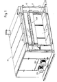
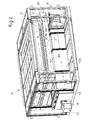
- a drying oven for textile products and the like i.e. fabrics, non-woven fabrics, fiber and staple products, etc. is indicated as a whole with number 10.
- the oven 10 comprises a frame 11 formed by a base and by uprights and crossbars supporting the components and the lateral and upper panels forming the outer casing.
- the oven 10 defines internally a drying tunnel 12, i.e. a room provided with an entrance and an exit defined on the front and back panel, across which the textile product to be dried is made pass.
- a drying tunnel 12 i.e. a room provided with an entrance and an exit defined on the front and back panel, across which the textile product to be dried is made pass.
- support means 13 are present for supporting the textile product, that are adequately embodied by a conveyor belt (schematized in dotted line only in figure 6 , and omitted in the other figures, as it is of the known type) supporting and transferring the fabric from the tunnel entrance to the exit, according to a known method.
- the surface of the conveyor belt 13, on which the textile product rests, is adequately perforated in a through manner in vertical direction to allow the air passage.
- heating means 14 constituted for example by a burner 15 arranged with the heating part inside a first environment 16 positioned in the initial part, or heat transfer means 16A, and two segments 17A, 17B of a duct, whose end parts correspond to the air ejection areas 18 on the conveyor belt 13, as it will be better described hereunder.
- the burner 15 is leaned against a first flank of the oven. From the first environment 16, where there is the burner 15, the two duct segments 17A and 17B continue inside the oven, in the lower part thereof, towards the opposite flank of the oven, where they meet the housings for respective air moving means 18A and 18B, preferably fans (i.e. rotating members suitable to generate an air flow at the desired pressure, speed and flow rate).
- air moving means 18A and 18B preferably fans (i.e. rotating members suitable to generate an air flow at the desired pressure, speed and flow rate).
- the segments 17A and 17B of the duct develop from the fans 18A and 18B upwards, until they meet respective air ejection structures 19A and 19B arranged respectively above and below the conveyor belt 13, to define the air ejection area towards the conveyor belt.
- Each ejection structure is substantially composed by the same components, and for the sake of brevity only the upper structure 19A will be described hereunder.
- the ejection structure 19A is composed by a first manifold 20, practically constituted by a space 20A; on this space are defined a first aperture 20B, for the fluid connection to the respective duct segment 17A (that is the conduit supplying heated air to the ejection structure), and a plurality of second apertures 20C for the connection to respective ejection chambers 21, that can be also defined as ejecting sleeves (with the term manifold it is possible to indicate for example an element for connecting a conduit with a plurality of other conduits that preferably comprises a space provided with apertures for the connection to the various conduits).
- these chambers 21 are each constituted by a tubular chamber, that in this example has rectangular section, fluidly connected at a first end to the above mentioned first manifold 20 and at the opposite second end to a second manifold 22, described below.
- the cross sections (i.e. orthogonal to the axis of development) of the ejection chambers 21 are of substantially constant area.
- the bottom wall 21A of the chambers (in the case of chambers of the ejection structure 19B, i.e. of the lower structure, the wall is that constituting the ceiling of the chamber), i.e. the horizontal wall facing the conveyor belt 13, presents, substantially along its development, a series of ejection openings (or holes) 23 directed toward the belt, i.e. downwards.
- each ejection structure 19A, 19B provides a "bank” (i.e. a series) of sleeves 21 parallel to and spaced from one another.
- the sleeves of each bank are at a same height, i.e. they are coplanar.
- the entrance to the first manifold 20, that is the area of connection to the supply duct segment 17A, is arranged about in correspondence to one of the two more external opposite ejection chambers 21 of the bank.
- external opposite ejection chambers 21 of the bank is intended the first or the last chamber of the series composing the linear bank of chambers.
- the first manifold 20 presents a constant cross section (i.e. orthogonal to the axis of its own development), while it is linearly decreasing as the manifold develops from that area towards the more external opposite chamber of the bank, thus balancing the pressure field inside the manifold.
- the opposite ends of the ejection chambers relative to the first manifold 20 are fluidly connected to a common second manifold 22, constituted in this example by a tubular space 22A with rectangular cross section (i.e. orthogonal to the axis of its own development), constant along its own development.
- a tubular space 22A with rectangular cross section i.e. orthogonal to the axis of its own development
- the length of this space is substantially equal to the overall width of the bank of ejection chambers 21.
- said space 22A is a closed space, with the exception of the apertures 22B; therefore, in this example, said space can fluidly communicate only with the ejection chambers.
- the number of the apertures on the space 22A for passage of air is equal to the number of the ejection chambers. It is evident that air can enter in said space 22A only from the ejection chambers 21 and can exit form said space only towards the same ejection chambers 21.
- the air entering in the space 22A from the apertures 22B is the air, with the exception of the air exited from the openings 23, entering the ejection chambers from the first manifold 20, that is the air coming from the supply duct segment 17A.
- the apertures 22B coincide with the opposite ends of the ejection chambers.
- the second manifold 22 can be manufactured as a piece that has to be fixed to the ejection chambers 21 or can be manufactured as a single piece integral with one or more chambers.
- the textile product to be dried is arranged on the conveyor belt 13 moving forward in the tunnel 12 of the oven according to the direction indicated by the arrow F shown in figure 2 .
- the air is heated by the burner 15 and moved by the fans 18A, 18B along the two segments 17A and 17B of air supply duct towards the respective ejection structures 19A and 19B arranged above and below the conveyor belt.
- the heated air enters the ejection chambers 21 and exits towards the conveyor belt 13 through the ejection openings 23, investing the textile product and drying it.
- Part of the ejected air is preferably recovered inside the air supply system, in correspondence of the heat transfer area 16A where there is the burner, while the remaining air exits from the oven.
- the air entering the ejection chambers 21 from the first manifold 20 distributes also in the second manifold 22, as it is communicating in a fluid manner.
- the pressure field in the chambers is substantially uniform on all the bank, i.e. with a substantially constant pressure value (constant means a pressure value varying locally in a negligible manner relative to the uniformity requirements of the ejection structure) thanks to, the fact that the ends of the chambers opposite to those of air entrance have been put into fluid communication by means of a common space. It should be noted that by varying the number of fan revolutions, i.e.
Landscapes
- Engineering & Computer Science (AREA)
- Mechanical Engineering (AREA)
- General Engineering & Computer Science (AREA)
- Textile Engineering (AREA)
- Treatment Of Fiber Materials (AREA)
- Drying Of Solid Materials (AREA)
Applications Claiming Priority (1)
| Application Number | Priority Date | Filing Date | Title |
|---|---|---|---|
| ITFI2010A000054A IT1399339B1 (it) | 2010-03-29 | 2010-03-29 | Struttura di eiezione di aria calda per forni di essiccazione di prodotti tessili. |
Publications (2)
| Publication Number | Publication Date |
|---|---|
| EP2372279A1 true EP2372279A1 (de) | 2011-10-05 |
| EP2372279B1 EP2372279B1 (de) | 2013-01-16 |
Family
ID=43126926
Family Applications (1)
| Application Number | Title | Priority Date | Filing Date |
|---|---|---|---|
| EP11425069A Active EP2372279B1 (de) | 2010-03-29 | 2011-03-22 | Struktur zur Einspeisung von heißer Luft zum Betrieb von Öfen für Textilprodukte |
Country Status (4)
| Country | Link |
|---|---|
| EP (1) | EP2372279B1 (de) |
| ES (1) | ES2400228T3 (de) |
| IT (1) | IT1399339B1 (de) |
| PT (1) | PT2372279E (de) |
Cited By (4)
| Publication number | Priority date | Publication date | Assignee | Title |
|---|---|---|---|---|
| EP3358061A1 (de) * | 2017-02-03 | 2018-08-08 | SICAM - S.R.L. Societa' Italiana Costruzioni Aeromeccaniche | Ofen für den textilsektor |
| IT201700039980A1 (it) * | 2017-04-11 | 2018-10-11 | Marco Gualtieri | Modulo ed impianto per il trattamento di fibre per l'ottenimento di un tessuto non tessuto |
| CN111721094A (zh) * | 2020-06-30 | 2020-09-29 | 杭州米娅纺织品有限公司 | 一种无纺布加工烘箱设备 |
| CN112239909A (zh) * | 2020-09-21 | 2021-01-19 | 江苏同欣化纤有限公司 | 一种帘子布织造机机台用的气压控制装置 |
Citations (4)
| Publication number | Priority date | Publication date | Assignee | Title |
|---|---|---|---|---|
| DE970045C (de) | 1949-01-21 | 1958-08-14 | Svenska Flaektfabriken Ab | Vorrichtung zum Trocknen von bahnfoermigem Material |
| US4094077A (en) * | 1975-10-04 | 1978-06-13 | Buttner-Schilde-Haas Ag | Dryer arrangement |
| US4295284A (en) | 1979-07-05 | 1981-10-20 | Marshall And Williams Company | Dryer range |
| EP0284710A2 (de) * | 1987-03-31 | 1988-10-05 | REGGIANI MACCHINE S.p.A. | Vorrichtung für die Trocknung und Wärmefixierung von Gewebe und dergleichen mittels Hochtemperatur-Luftzirkulation innerhalb eines Tunnels mit einer Vielzahl von Behandlungsräumen |
-
2010
- 2010-03-29 IT ITFI2010A000054A patent/IT1399339B1/it active
-
2011
- 2011-03-22 ES ES11425069T patent/ES2400228T3/es active Active
- 2011-03-22 PT PT114250699T patent/PT2372279E/pt unknown
- 2011-03-22 EP EP11425069A patent/EP2372279B1/de active Active
Patent Citations (4)
| Publication number | Priority date | Publication date | Assignee | Title |
|---|---|---|---|---|
| DE970045C (de) | 1949-01-21 | 1958-08-14 | Svenska Flaektfabriken Ab | Vorrichtung zum Trocknen von bahnfoermigem Material |
| US4094077A (en) * | 1975-10-04 | 1978-06-13 | Buttner-Schilde-Haas Ag | Dryer arrangement |
| US4295284A (en) | 1979-07-05 | 1981-10-20 | Marshall And Williams Company | Dryer range |
| EP0284710A2 (de) * | 1987-03-31 | 1988-10-05 | REGGIANI MACCHINE S.p.A. | Vorrichtung für die Trocknung und Wärmefixierung von Gewebe und dergleichen mittels Hochtemperatur-Luftzirkulation innerhalb eines Tunnels mit einer Vielzahl von Behandlungsräumen |
Cited By (6)
| Publication number | Priority date | Publication date | Assignee | Title |
|---|---|---|---|---|
| EP3358061A1 (de) * | 2017-02-03 | 2018-08-08 | SICAM - S.R.L. Societa' Italiana Costruzioni Aeromeccaniche | Ofen für den textilsektor |
| IT201700039980A1 (it) * | 2017-04-11 | 2018-10-11 | Marco Gualtieri | Modulo ed impianto per il trattamento di fibre per l'ottenimento di un tessuto non tessuto |
| EP3388566A1 (de) * | 2017-04-11 | 2018-10-17 | Gualtieri, Marco | Modul und system zur behandlung von fasern zur herstellung eines vliesstoffes |
| US11131046B2 (en) | 2017-04-11 | 2021-09-28 | Marco GUALTIERI | Module and system for the treatment of fibres for obtaining a non-woven fabric |
| CN111721094A (zh) * | 2020-06-30 | 2020-09-29 | 杭州米娅纺织品有限公司 | 一种无纺布加工烘箱设备 |
| CN112239909A (zh) * | 2020-09-21 | 2021-01-19 | 江苏同欣化纤有限公司 | 一种帘子布织造机机台用的气压控制装置 |
Also Published As
| Publication number | Publication date |
|---|---|
| EP2372279B1 (de) | 2013-01-16 |
| PT2372279E (pt) | 2013-04-03 |
| ES2400228T3 (es) | 2013-04-08 |
| IT1399339B1 (it) | 2013-04-16 |
| ITFI20100054A1 (it) | 2011-09-30 |
Similar Documents
| Publication | Publication Date | Title |
|---|---|---|
| EP2372279B1 (de) | Struktur zur Einspeisung von heißer Luft zum Betrieb von Öfen für Textilprodukte | |
| US9696088B2 (en) | Dryer for a textile product web | |
| CN108351167B (zh) | 处理装置和处理方法 | |
| ES2965516T3 (es) | Dispositivo para la extrusión de filamentos y fabricación de materiales no tejidos hilados | |
| CN105177903B (zh) | 一种节能高效的蒸汽定型机 | |
| US9809909B2 (en) | Fiber oxidation oven with multiple independently controllable heating systems | |
| ITMI960970A1 (it) | Impianto per la produzione di un nastro di tessuto di filatura di fi- li continui termoplastici | |
| DK2663673T3 (en) | Spinneret bundle | |
| JP6537339B2 (ja) | 植物栽培装置 | |
| ES2784362T3 (es) | Horno de cocción con transferencia de calor combinada | |
| CA2667506C (en) | End section of an air dryer, air dryer, method in the end part of an air dryer and use of fan | |
| US10132020B2 (en) | Apparatus for the thermal treatment of a textile web | |
| US7997003B2 (en) | Multistage continuous dryer, especially for plate-shaped products | |
| US20090038176A1 (en) | Multistage continuous dryer, especially for plate-shaped products | |
| JP2013516590A (ja) | 連続的に搬送されるシート材料を熱処理するための装置および方法 | |
| CN204898322U (zh) | 一种节能高效的蒸汽定型机 | |
| US5134866A (en) | Apparatus for the thermal treatment of textile fibers | |
| US10458710B2 (en) | Supply plenum for center-to-ends fiber oxidation oven | |
| KR102017543B1 (ko) | 직물, 셀룰로오스 및 다른 섬유 재료를 위한 유체 처리 유닛 그리고 또한 유체 처리 방법 | |
| EP3388566A1 (de) | Modul und system zur behandlung von fasern zur herstellung eines vliesstoffes | |
| US3538619A (en) | Apparatus for drying continuously moving elongated flexible means | |
| CN113957547A (zh) | 一种多用途网织纤维原料的生产工艺方法 | |
| EP1167907B1 (de) | Anlage zur kontinuierlichen Trocknung von Bausteinprodukten | |
| US20040226457A1 (en) | Dough proofing apparatus and related methods | |
| US3983839A (en) | Multiple coating apparatus |
Legal Events
| Date | Code | Title | Description |
|---|---|---|---|
| PUAI | Public reference made under article 153(3) epc to a published international application that has entered the european phase |
Free format text: ORIGINAL CODE: 0009012 |
|
| AK | Designated contracting states |
Kind code of ref document: A1 Designated state(s): AL AT BE BG CH CY CZ DE DK EE ES FI FR GB GR HR HU IE IS IT LI LT LU LV MC MK MT NL NO PL PT RO RS SE SI SK SM TR |
|
| AX | Request for extension of the european patent |
Extension state: BA ME |
|
| 17P | Request for examination filed |
Effective date: 20120402 |
|
| GRAP | Despatch of communication of intention to grant a patent |
Free format text: ORIGINAL CODE: EPIDOSNIGR1 |
|
| RIC1 | Information provided on ipc code assigned before grant |
Ipc: F26B 13/10 20060101AFI20120710BHEP |
|
| GRAS | Grant fee paid |
Free format text: ORIGINAL CODE: EPIDOSNIGR3 |
|
| GRAA | (expected) grant |
Free format text: ORIGINAL CODE: 0009210 |
|
| AK | Designated contracting states |
Kind code of ref document: B1 Designated state(s): AL AT BE BG CH CY CZ DE DK EE ES FI FR GB GR HR HU IE IS IT LI LT LU LV MC MK MT NL NO PL PT RO RS SE SI SK SM TR |
|
| REG | Reference to a national code |
Ref country code: GB Ref legal event code: FG4D |
|
| REG | Reference to a national code |
Ref country code: CH Ref legal event code: EP Ref country code: CH Ref legal event code: NV Representative=s name: BOVARD AG, CH |
|
| REG | Reference to a national code |
Ref country code: IE Ref legal event code: FG4D |
|
| REG | Reference to a national code |
Ref country code: AT Ref legal event code: REF Ref document number: 594101 Country of ref document: AT Kind code of ref document: T Effective date: 20130215 Ref country code: CH Ref legal event code: EP Ref country code: CH Ref legal event code: NV Representative=s name: BOVARD AG, CH |
|
| REG | Reference to a national code |
Ref country code: DE Ref legal event code: R096 Ref document number: 602011000801 Country of ref document: DE Effective date: 20130321 |
|
| REG | Reference to a national code |
Ref country code: PT Ref legal event code: SC4A Free format text: AVAILABILITY OF NATIONAL TRANSLATION Effective date: 20130326 |
|
| REG | Reference to a national code |
Ref country code: ES Ref legal event code: FG2A Ref document number: 2400228 Country of ref document: ES Kind code of ref document: T3 Effective date: 20130408 |
|
| REG | Reference to a national code |
Ref country code: NL Ref legal event code: VDEP Effective date: 20130116 |
|
| REG | Reference to a national code |
Ref country code: LT Ref legal event code: MG4D |
|
| PG25 | Lapsed in a contracting state [announced via postgrant information from national office to epo] |
Ref country code: LT Free format text: LAPSE BECAUSE OF FAILURE TO SUBMIT A TRANSLATION OF THE DESCRIPTION OR TO PAY THE FEE WITHIN THE PRESCRIBED TIME-LIMIT Effective date: 20130116 Ref country code: BE Free format text: LAPSE BECAUSE OF FAILURE TO SUBMIT A TRANSLATION OF THE DESCRIPTION OR TO PAY THE FEE WITHIN THE PRESCRIBED TIME-LIMIT Effective date: 20130116 Ref country code: SE Free format text: LAPSE BECAUSE OF FAILURE TO SUBMIT A TRANSLATION OF THE DESCRIPTION OR TO PAY THE FEE WITHIN THE PRESCRIBED TIME-LIMIT Effective date: 20130116 Ref country code: BG Free format text: LAPSE BECAUSE OF FAILURE TO SUBMIT A TRANSLATION OF THE DESCRIPTION OR TO PAY THE FEE WITHIN THE PRESCRIBED TIME-LIMIT Effective date: 20130416 Ref country code: IS Free format text: LAPSE BECAUSE OF FAILURE TO SUBMIT A TRANSLATION OF THE DESCRIPTION OR TO PAY THE FEE WITHIN THE PRESCRIBED TIME-LIMIT Effective date: 20130516 Ref country code: NO Free format text: LAPSE BECAUSE OF FAILURE TO SUBMIT A TRANSLATION OF THE DESCRIPTION OR TO PAY THE FEE WITHIN THE PRESCRIBED TIME-LIMIT Effective date: 20130416 |
|
| PG25 | Lapsed in a contracting state [announced via postgrant information from national office to epo] |
Ref country code: FI Free format text: LAPSE BECAUSE OF FAILURE TO SUBMIT A TRANSLATION OF THE DESCRIPTION OR TO PAY THE FEE WITHIN THE PRESCRIBED TIME-LIMIT Effective date: 20130116 Ref country code: PL Free format text: LAPSE BECAUSE OF FAILURE TO SUBMIT A TRANSLATION OF THE DESCRIPTION OR TO PAY THE FEE WITHIN THE PRESCRIBED TIME-LIMIT Effective date: 20130116 Ref country code: NL Free format text: LAPSE BECAUSE OF FAILURE TO SUBMIT A TRANSLATION OF THE DESCRIPTION OR TO PAY THE FEE WITHIN THE PRESCRIBED TIME-LIMIT Effective date: 20130116 Ref country code: SI Free format text: LAPSE BECAUSE OF FAILURE TO SUBMIT A TRANSLATION OF THE DESCRIPTION OR TO PAY THE FEE WITHIN THE PRESCRIBED TIME-LIMIT Effective date: 20130116 Ref country code: LV Free format text: LAPSE BECAUSE OF FAILURE TO SUBMIT A TRANSLATION OF THE DESCRIPTION OR TO PAY THE FEE WITHIN THE PRESCRIBED TIME-LIMIT Effective date: 20130116 Ref country code: GR Free format text: LAPSE BECAUSE OF FAILURE TO SUBMIT A TRANSLATION OF THE DESCRIPTION OR TO PAY THE FEE WITHIN THE PRESCRIBED TIME-LIMIT Effective date: 20130417 |
|
| PG25 | Lapsed in a contracting state [announced via postgrant information from national office to epo] |
Ref country code: RS Free format text: LAPSE BECAUSE OF FAILURE TO SUBMIT A TRANSLATION OF THE DESCRIPTION OR TO PAY THE FEE WITHIN THE PRESCRIBED TIME-LIMIT Effective date: 20130116 Ref country code: HR Free format text: LAPSE BECAUSE OF FAILURE TO SUBMIT A TRANSLATION OF THE DESCRIPTION OR TO PAY THE FEE WITHIN THE PRESCRIBED TIME-LIMIT Effective date: 20130116 |
|
| PG25 | Lapsed in a contracting state [announced via postgrant information from national office to epo] |
Ref country code: SK Free format text: LAPSE BECAUSE OF FAILURE TO SUBMIT A TRANSLATION OF THE DESCRIPTION OR TO PAY THE FEE WITHIN THE PRESCRIBED TIME-LIMIT Effective date: 20130116 Ref country code: EE Free format text: LAPSE BECAUSE OF FAILURE TO SUBMIT A TRANSLATION OF THE DESCRIPTION OR TO PAY THE FEE WITHIN THE PRESCRIBED TIME-LIMIT Effective date: 20130116 Ref country code: RO Free format text: LAPSE BECAUSE OF FAILURE TO SUBMIT A TRANSLATION OF THE DESCRIPTION OR TO PAY THE FEE WITHIN THE PRESCRIBED TIME-LIMIT Effective date: 20130116 Ref country code: MC Free format text: LAPSE BECAUSE OF NON-PAYMENT OF DUE FEES Effective date: 20130331 Ref country code: CZ Free format text: LAPSE BECAUSE OF FAILURE TO SUBMIT A TRANSLATION OF THE DESCRIPTION OR TO PAY THE FEE WITHIN THE PRESCRIBED TIME-LIMIT Effective date: 20130116 Ref country code: DK Free format text: LAPSE BECAUSE OF FAILURE TO SUBMIT A TRANSLATION OF THE DESCRIPTION OR TO PAY THE FEE WITHIN THE PRESCRIBED TIME-LIMIT Effective date: 20130116 |
|
| PLBE | No opposition filed within time limit |
Free format text: ORIGINAL CODE: 0009261 |
|
| STAA | Information on the status of an ep patent application or granted ep patent |
Free format text: STATUS: NO OPPOSITION FILED WITHIN TIME LIMIT |
|
| PG25 | Lapsed in a contracting state [announced via postgrant information from national office to epo] |
Ref country code: CY Free format text: LAPSE BECAUSE OF FAILURE TO SUBMIT A TRANSLATION OF THE DESCRIPTION OR TO PAY THE FEE WITHIN THE PRESCRIBED TIME-LIMIT Effective date: 20130116 |
|
| 26N | No opposition filed |
Effective date: 20131017 |
|
| REG | Reference to a national code |
Ref country code: IE Ref legal event code: MM4A |
|
| PG25 | Lapsed in a contracting state [announced via postgrant information from national office to epo] |
Ref country code: IE Free format text: LAPSE BECAUSE OF NON-PAYMENT OF DUE FEES Effective date: 20130322 Ref country code: AL Free format text: LAPSE BECAUSE OF FAILURE TO SUBMIT A TRANSLATION OF THE DESCRIPTION OR TO PAY THE FEE WITHIN THE PRESCRIBED TIME-LIMIT Effective date: 20130116 |
|
| REG | Reference to a national code |
Ref country code: DE Ref legal event code: R097 Ref document number: 602011000801 Country of ref document: DE Effective date: 20131017 |
|
| PG25 | Lapsed in a contracting state [announced via postgrant information from national office to epo] |
Ref country code: MT Free format text: LAPSE BECAUSE OF FAILURE TO SUBMIT A TRANSLATION OF THE DESCRIPTION OR TO PAY THE FEE WITHIN THE PRESCRIBED TIME-LIMIT Effective date: 20130116 |
|
| REG | Reference to a national code |
Ref country code: FR Ref legal event code: PLFP Year of fee payment: 5 |
|
| PG25 | Lapsed in a contracting state [announced via postgrant information from national office to epo] |
Ref country code: SM Free format text: LAPSE BECAUSE OF FAILURE TO SUBMIT A TRANSLATION OF THE DESCRIPTION OR TO PAY THE FEE WITHIN THE PRESCRIBED TIME-LIMIT Effective date: 20130116 |
|
| PG25 | Lapsed in a contracting state [announced via postgrant information from national office to epo] |
Ref country code: HU Free format text: LAPSE BECAUSE OF FAILURE TO SUBMIT A TRANSLATION OF THE DESCRIPTION OR TO PAY THE FEE WITHIN THE PRESCRIBED TIME-LIMIT; INVALID AB INITIO Effective date: 20110322 Ref country code: MK Free format text: LAPSE BECAUSE OF FAILURE TO SUBMIT A TRANSLATION OF THE DESCRIPTION OR TO PAY THE FEE WITHIN THE PRESCRIBED TIME-LIMIT Effective date: 20130116 Ref country code: LU Free format text: LAPSE BECAUSE OF NON-PAYMENT OF DUE FEES Effective date: 20130322 |
|
| GBPC | Gb: european patent ceased through non-payment of renewal fee |
Effective date: 20150322 |
|
| PG25 | Lapsed in a contracting state [announced via postgrant information from national office to epo] |
Ref country code: GB Free format text: LAPSE BECAUSE OF NON-PAYMENT OF DUE FEES Effective date: 20150322 |
|
| REG | Reference to a national code |
Ref country code: FR Ref legal event code: PLFP Year of fee payment: 6 |
|
| REG | Reference to a national code |
Ref country code: FR Ref legal event code: PLFP Year of fee payment: 7 |
|
| REG | Reference to a national code |
Ref country code: FR Ref legal event code: PLFP Year of fee payment: 8 |
|
| REG | Reference to a national code |
Ref country code: DE Ref legal event code: R082 Ref document number: 602011000801 Country of ref document: DE Representative=s name: GLAWE DELFS MOLL PARTNERSCHAFT MBB VON PATENT-, DE Ref country code: DE Ref legal event code: R082 Ref document number: 602011000801 Country of ref document: DE Representative=s name: GLAWE DELFS MOLL PARTGMBB, DE |
|
| PGFP | Annual fee paid to national office [announced via postgrant information from national office to epo] |
Ref country code: ES Payment date: 20250415 Year of fee payment: 15 |
|
| PGFP | Annual fee paid to national office [announced via postgrant information from national office to epo] |
Ref country code: CH Payment date: 20250401 Year of fee payment: 15 |
|
| REG | Reference to a national code |
Ref country code: CH Ref legal event code: U11 Free format text: ST27 STATUS EVENT CODE: U-0-0-U10-U11 (AS PROVIDED BY THE NATIONAL OFFICE) Effective date: 20260401 |
|
| PGFP | Annual fee paid to national office [announced via postgrant information from national office to epo] |
Ref country code: DE Payment date: 20260320 Year of fee payment: 16 |
|
| PGFP | Annual fee paid to national office [announced via postgrant information from national office to epo] |
Ref country code: AT Payment date: 20260318 Year of fee payment: 16 |
|
| PGFP | Annual fee paid to national office [announced via postgrant information from national office to epo] |
Ref country code: IT Payment date: 20260226 Year of fee payment: 16 |
|
| PGFP | Annual fee paid to national office [announced via postgrant information from national office to epo] |
Ref country code: FR Payment date: 20260323 Year of fee payment: 16 |
|
| PGFP | Annual fee paid to national office [announced via postgrant information from national office to epo] |
Ref country code: TR Payment date: 20260305 Year of fee payment: 16 |
|
| PGFP | Annual fee paid to national office [announced via postgrant information from national office to epo] |
Ref country code: PT Payment date: 20260302 Year of fee payment: 16 |