EP2372896A1 - Dispositif moteur, dispositif et procédé d'entraînement de rotor - Google Patents
Dispositif moteur, dispositif et procédé d'entraînement de rotor Download PDFInfo
- Publication number
- EP2372896A1 EP2372896A1 EP09834474A EP09834474A EP2372896A1 EP 2372896 A1 EP2372896 A1 EP 2372896A1 EP 09834474 A EP09834474 A EP 09834474A EP 09834474 A EP09834474 A EP 09834474A EP 2372896 A1 EP2372896 A1 EP 2372896A1
- Authority
- EP
- European Patent Office
- Prior art keywords
- rotor
- transmission member
- motor device
- state
- transmission
- Prior art date
- Legal status (The legal status is an assumption and is not a legal conclusion. Google has not performed a legal analysis and makes no representation as to the accuracy of the status listed.)
- Withdrawn
Links
Images








Classifications
-
- H—ELECTRICITY
- H02—GENERATION; CONVERSION OR DISTRIBUTION OF ELECTRIC POWER
- H02N—ELECTRIC MACHINES NOT OTHERWISE PROVIDED FOR
- H02N2/00—Electric machines in general using piezoelectric effect, electrostriction or magnetostriction
-
- H—ELECTRICITY
- H02—GENERATION; CONVERSION OR DISTRIBUTION OF ELECTRIC POWER
- H02N—ELECTRIC MACHINES NOT OTHERWISE PROVIDED FOR
- H02N2/00—Electric machines in general using piezoelectric effect, electrostriction or magnetostriction
- H02N2/10—Electric machines in general using piezoelectric effect, electrostriction or magnetostriction producing rotary motion, e.g. rotary motors
- H02N2/101—Electric machines in general using piezoelectric effect, electrostriction or magnetostriction producing rotary motion, e.g. rotary motors using intermittent driving, e.g. step motors
-
- H—ELECTRICITY
- H02—GENERATION; CONVERSION OR DISTRIBUTION OF ELECTRIC POWER
- H02N—ELECTRIC MACHINES NOT OTHERWISE PROVIDED FOR
- H02N2/00—Electric machines in general using piezoelectric effect, electrostriction or magnetostriction
- H02N2/10—Electric machines in general using piezoelectric effect, electrostriction or magnetostriction producing rotary motion, e.g. rotary motors
-
- H—ELECTRICITY
- H02—GENERATION; CONVERSION OR DISTRIBUTION OF ELECTRIC POWER
- H02N—ELECTRIC MACHINES NOT OTHERWISE PROVIDED FOR
- H02N2/00—Electric machines in general using piezoelectric effect, electrostriction or magnetostriction
- H02N2/10—Electric machines in general using piezoelectric effect, electrostriction or magnetostriction producing rotary motion, e.g. rotary motors
- H02N2/16—Electric machines in general using piezoelectric effect, electrostriction or magnetostriction producing rotary motion, e.g. rotary motors using travelling waves, i.e. Rayleigh surface waves
Definitions
- the present invention relates to a motor device, an apparatus, and a driving method for a rotor.
- a motor device is used as an actuator which drives a turning machine.
- a motor device for example, a motor device, such as an electric motor or an ultrasonic motor, which can generate high torque is widely known.
- a motor device which drives a more precise portion such as a joint part of a humanoid robot (an apparatus)
- a configuration in which such a miniaturized motor can perform minute and high precision driving such as torque control as an existing motor; an electric motor or an ultrasonic motor.
- a purpose of some aspects of the present invention is to provide a motor device suitable for miniaturization, and capable of generating high torque, and easily performing torque control.
- An aspect of the invention provides a motor device that includes a rotor, a transmission member wound around at least a portion of an outer periphery of the rotor, a moving part connected to the transmission member to move the transmission member, and a control unit which makes the moving part perform a driving operation of moving the transmission member by a predetermined distance in a state where a torque transmission state is brought between the rotor and the transmission member, and a returning operation of returning the transmission member to a predetermined position in a state where the torque transmission state is released.
- An another aspect of the invention provides a motor device that includes a rotor, a transmission member wound around the rotor, and a control unit which makes a vibrational wave propagate in one direction of the transmission member, and makes the transmission member perform a wavelike motion, thereby rotating the rotor in a direction opposite to the one direction.
- An another aspect of the invention provides a driving method of a rotor that includes a driving step of moving a transmission member by a predetermined distance in a state where a torque transmission state is brought between the rotor and the transmission member wound around the rotor, and a returning step of returning the transmission member to a predetermined position where the torque transmission state is released.
- Another aspect of the invention provides an apparatus that includes an arm portion; and a motor device according to the above-described aspect that drives the arm portion.
- FIG. 1 is a schematic configuration view showing an example of a motor device MTR according to this embodiment.
- the motor device MTR has a rotor SF, a transmission member BT, a moving part AC, a supporting member BS, and a control unit CONT.
- the motor device MTR is configured such that the rotor SF and the moving part AC are supported by the supporting member BS, and the transmission member BT connected to the moving part AC is wound around the rotor SF.
- the control unit CONT is electrical connected to the moving part AC so that a control signal thereof is supplied to the moving part AC.
- FIG. 2 is a view showing the configuration of the rotor SF.
- the rotor SF is formed in a cylindrical shape, and has a shaft portion 11 and a diameter-enlarged portion 12.
- the shaft portion 11 is rotatably supported by a bearing 41 (refer to FIG. 1 ) of the supporting member BS via, for example, a bearing mechanism (not shown), etc.
- the diameter-enlarged portion 12 is a portion which is formed so that its diameter is larger than that of the shaft portion 11. In other words, the diameter-enlarged portion 12 has a larger diameter than the shaft portion 11.
- the shaft portion 11 and the diameter-enlarged portion 12 are formed so as to have a common rotational axis.
- the surface of the diameter-enlarged portion 12 becomes an outer periphery (an outer surface, an outer circumferential surface) which the transmission member BT is wrapped.
- the rotor SF is made of, for example, a conductive material, such as aluminum. Alternatively or also, the rotor SF can be made by use of a material other than aluminum. In the present embodiment, the rotor SF has a detector (not shown) which can detect the peripheral speed of the diameter-enlarged portion 12.
- the diameter of the diameter-enlarged portion 12 can be set to, for example, about 10 mm.
- the diameter of the diameter-enlarged portion 12 can be approximately 0.5, 1, 2, 3, 4, 5, 6, 7, 8, 9, 10, 15, 20, 25, or 30mm.
- FIG. 3 is a drawing showing the configuration of the transmission member BT.
- the transmission member BT is formed in the shape of a belt, and is wound around the diameter-enlarged portion 12 of the rotor SF. Illustration of the rotor SF is omitted in FIG. 3 .
- the transmission member BT is made of, for example, a conductive material, such as steel. Alternatively or also, the transmission member BT can be made by use of a material other than steel.
- the transmission member BT is adapted to be wound around and cross the diameter-enlarged portion 12, for example, by one rotation. In other words, the substantial number of turns of the transmission member BT on the diameter-enlarged portion 12 is about 1.0.
- the substantial number of turns of the transmission member BT on the diameter-enlarged portion 12 can be, for example, about 0.2, 0.4, 0.6, 0.8, 1.2, 1.4, 1.6, 1.8, 2.0, or more.
- a crossing portion 21 of the transmission member BT has a cross-belt structure. Specifically, in the crossing portion 21, a first end 22A of the transmission member BT is bifurcated, and a second end 22B of the transmission member BT becomes narrow. For this reason, the transmission member BT crosses in a state where the second end 22B is arranged between the two prongs of the first end 22A. The first end 22A and the second end 22B of the transmission member BT are connected to the moving part AC, respectively.
- a plurality of (for example three) such transmission members BT is provided along an axial direction of the rotor SF.
- the respective widths (dimensions in the direction of the rotational axis) of the three transmission members BT are made equal to each other.
- the respective crossing portions 21 of the three transmission members BT are arranged at positions which deviate (shift) at equal angles, specifically, at positions which deviate (shift) by every 120°, in a circumferential direction of the rotor SF.
- the coefficients of friction between the three transmission members BT and the diameter-enlarged portion 12 of the rotor SF are set to be, for example, 0.3, respectively.
- the number of the transmission members BT with respect to one the rotor SF can be, for example, 1, 2, 4, 5, 6, 7, 8, 9, 10 or more.
- the coefficients of friction between the transmission member BT and the diameter-enlarged portion 12 of the rotor SF can be set to be, for example, approximately 0.1, 0.2, 0.3, 0.4, 0.5, 0.6, 0.7, 0.8, 0.9, or more..
- FIG. 4 is a drawing showing the configuration of the moving part AC.
- FIG. 4 a configuration in which the moving part AC is connected to the transmission member BT is shown.
- At least a part of the moving part AC is provided in the crossing portion 21 or in the adjacent part of the crossing portion 21 of each transmission member BT.
- the moving part AC has a holding member 31, electrostrictive elements 32, connecting portions 33, and spring mechanisms 34.
- the holding member 31 is formed substantially along a tangential direction of the circumference of the rotor SF in the above crossing portion 21.
- the tangential direction of the holding member 31 is longitudinal.
- the holding member 31 has a longitudinal axis along the tangential direction.
- the holding member 31 has recesses 31a, respectively, at both longitudinal ends thereof.
- the bottom of each recess 31 a is provided with an opening 31 b.
- each holding member 31 is fixed to each supporting member BS.
- the electrostrictive element 32 is provided in each recess 31a of the holding member 31. For this reason, a pair of the electrostrictive elements 32 is provided so as to sandwich the crossing portion 21 as a reference position.
- the pair of electrostrictive elements 32 (a first electrostrictive element 32A and a second electrostrictive element 32B) are hollow cylinders (cylindrical shapes, cylindrical tube shapes), respectively.
- the pair of electrostrictive elements 32 (a first electrostrictive element 32A and a second electrostrictive element 32B) are provided so as to be capable of deforming in directions opposite to each other with respect to the crossing portion 21 that is a reference position (or to be capable of extending outward with respect to the crossing portion 21).
- first electrostrictive element 32A and the second electrostrictive element 32B for example, piezoelectric elements, etc. are used.
- first electrostrictive element 32A or the second electrostrictive element 32B an element other than piezoelectric element can be used.
- the connecting portions 33 are portions which connect the first end 22A and the first electrostrictive element 32A of the transmission member BT, and connect the second end 22B and the second electrostrictive element 32B.
- Each connecting portion 33 has a flange member 33a and a rod member 33b.
- the flange members 33a are provided so as to abut on an end face of the first electrostrictive element 32A and an end face of the second electrostrictive element 32B, respectively.
- the rod member 33b is integrally provided with the flange member 33a.
- the rod members 33b are provided so as to pass through the first electrostrictive element 32A and the second electrostrictive element 32B, respectively, and so as to pass through the openings 31b of the recesses 31a, respectively.
- the tips of the rod members 33b are respectively connected to the first end 22A and the second end 22B of the transmission member BT.
- the spring mechanism 34 is adapted to press the flange member 33a towards the crossing portion 21.
- the spring mechanism 34 is constituted of, for example, a leaf-spring member 34a.
- the leaf-spring member 34a has, for example, one end connected to the outer surface of the flange member 33a via a nut, etc., and folded back so as to bypass the flange member 33a, and has the other end fixed to the end face of the holding member 31.
- the other end side of the leaf-spring member 34a is bent so as to abut on the end face of the holding member 31.
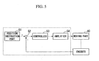
- FIG. 5 is a block diagram showing the configuration of the control unit CONT.
- the control unit CONT has a position instruction part 51, an operation part 52, a controller 53, and an amplifier 54.
- the motor device MTR is adapted so that the output value of the moving part AC can be detected by an encoder.
- the control unit CONT converts deformation volume, and a speed error of deformation in the first electrostrictive element 32A and the second electrostrictive element 32B into thrust, on the basis of the detection value of the encoder, and takes the thrust as an instruction value for the moving part AC.
- FIGS. 6 and 7 show the configuration of the transmission member BT in the state of being not wound around the rotor SF. Since the same operation is performed by the first electrostrictive element 32A and the second electrostrictive element 32B (here, the movement direction of the transmission member BT becomes an opposite direction) in the description of the operation of the moving part AC, the first electrostrictive element 32A will be representatively described here.
- the flange member 33a is pressed towards the crossing portion 21 by the spring mechanism 34.
- the first electrostrictive element 32A deforms so as to expand.
- the first electrostrictive element 32A has the contact end portion with the holding member 31 as a fixed end and lengthens outward with respect to the crossing portion 21.
- the force caused by the deformation act in a direction (hereinafter referred to as "outward") away from the crossing portion 21. This force presses the flange member 33a outward.
- Equation 2 the torque transmitted to the rotor SF is uniquely determined by the tension T 1 of the first electrostrictive element 32A.
- a coefficient portion of T 1 of the right side of Equation 2 depends on the coefficient of friction ⁇ between the transmission member BT and the rotor SF, and the effective winding angle ⁇ of the transmission member BT, respectively.
- FIG. 8 is a graph showing the relationship between the effective winding angle ⁇ and the value of a coefficient portion when the coefficient of friction ⁇ is changed.
- the abscissa axis of the graph represents the effective winding angle ⁇
- the ordinate axis of the graph represents the value of a coefficient portion.
- the value of the coefficient portion becomes equal to or more than 0.8 when the effective winding angle ⁇ is equal to or more than 300°. It can be understood from this that, if the coefficient of friction ⁇ is 0.3, 80% or more of the tension T 1 caused by the first electrostrictive element 32A contributes to the torque of the rotor SF by setting the effective winding angle ⁇ to 300° or more. Besides this winding angle, it is estimated from the graph of FIG. 8 that the value of the coefficient portion becomes larger as, for example, the coefficient of friction between the transmission member BT and the rotor SF is made larger.
- the magnitude of the torque is uniquely determined by the tension T 1 of the first electrostrictive element 32A, and is not related to the moving distance of the transmission member BT. Accordingly, for example, even if the piezoelectric elements used for the first electrostrictive element 32A and the second electrostrictive element 32B are small elements of about several millimeters, a force of hundreds or more of Newtons (Ns) can be output. Thus, a very large torque can be given.
- Ns Newtons
- the control unit CONT can control the first electrostrictive element 32A and the second electrostrictive element 32B to rotate (or to rotary drive) the rotor SF.
- the control unit CONT can comprises at least a driving mode and a returning mode.
- the control unit CONT first makes the first electrostrictive element 32A and the second electrostrictive element 32B deform so that the first end 22A and the second end 22B move outward, respectively (tension generating operation, tension generating mode).
- tension T 1 is generated on the side of the first end 22A of the transmission member BT
- the tension T 2 is generated on the side of the second end 22B of the transmission member BT. Accordingly, the effective tension (T 1 -T 2 ) is generated in the transmission member BT.
- the control unit CONT makes the first electrostrictive element 32A and the second electrostrictive element 32B deform so that the first end 22A of the transmission member BT moves outward and the second end 22B moves inward (driving operation, driving mode), as shown in FIG. 10 , while holding the state where the effective tension is generated in the transmission member BT.
- the control unit CONT makes the moving distance of the first end 22A and the moving distance of the second end 22B equal to each other.
- the transmission member BT moves in a state where a frictional force has been generated between the transmission member BT and the rotor SF, and along with this movement, the rotor SF rotates in the direction of ⁇ in the drawing.
- the coefficient of friction ⁇ between the transmission member BT and the rotor SF is 0.3, and the transmission member BT is wound around the diameter-enlarged portion 12 of the rotor SF by one rotation (360°). Accordingly, referring to the graph of FIG. 8 , about 85% of the tension T 1 of the first electrostrictive element 32A is transmitted to the rotor SF as torque.
- the control unit CONT makes only the first electrostrictive element 32A deform so that the first end 22A returns to a starting position (a given position) of driving and the second end 22B does not move, as shown in FIG. 11 , after the first end 22A and the second end 22B are moved by a predetermined distance.
- the first end 22A moves inward, and the winding of the transmission member BT is loosened. That is, the effective tension transmitted to the transmission member BT is released. In this state, a frictional force is not generated between the transmission member BT and the rotor SF, and the rotor SF continues rotating by inertia.
- the control unit CONT makes the second electrostrictive element 32B deform so that the second end 22B returns to a starting position (a given position) of driving, as shown in FIG. 12 , after the winding of the transmission member BT is loosened.
- the second end 22B of the transmission member BT returns to the starting position (given position) of driving (returning operation, returning mode).
- the control unit CONT makes the first electrostrictive element 32A deform and makes the first end 22A move outward (tension generating operation, tension generating mode).
- tension generating operation tension generating mode
- the control unit CONT makes the first electrostrictive element 32A deform so that the first end 22A of the transmission member BT moves outward, and makes the second electrostrictive element 32B deform so that the second end 22B moves inward (driving operation, driving mode). At this time, the moving distance of the first end 22A and the moving distance of the second end 22B are made equal to each other.
- the transmission member BT moves in a state where a frictional force has been generated between the transmission member BT and the rotor SF, and along with this movement, the rotor SF rotates in the direction of ⁇ .
- control unit CONT makes the effective tension transmitted to the transmission member BT released again.
- the control unit CONT makes the first end 22A and the second end 22B of the transmission member BT move so as to return to the starting position (returning operation, returning mode).
- the control unit CONT makes the moving part AC repeat the above driving operation and returning operation in this way, the rotor SF continues rotating in the direction of ⁇ . In other words, tension generating mode, driving mode, and returning mode are repeated in turn.
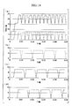
- FIG. 14 is a graph showing the relationship between tension and time when the three-phase transmission members BT and moving parts AC are alternately driven.
- the abscissa axis of the graph represents time, and the ordinate axis of the graph represents tension.
- the broken line, one-dot chain line, and two-dot chain line of the graphs show driving of the respective phases.
- the solid line of the graph shows the tension in the whole rotor SF.
- Parts (b)-(d) of FIG. 14 show driving of the respective phases in part (a) of FIG. 14 .
- one-phase driving time is set to 0.01 second. As shown in this drawing, it can be understood that, when driving is alternately performed in three phase, the amplitude of vibration of the tension is suppressed to be small, and stable driving can be performed.
- the moving part AC is made to perform the driving operation and the returning operation in a state where the transmission member BT is wound around at least a portion of the rotor SF.
- torque is uniquely determined by one tension to be transmitted to the transmission member BT. Accordingly, even if a speed reducer, etc. is not used, and the moving part AC is small, it is possible to transmit high torque to the rotor SF. This makes it possible to obtain a small motor device MTR capable of generating high torque. Additionally, even if the moving part AC is small, it is possible to rotate the rotor SF with high efficiency.
- the torque transmitted to the rotor SF can be controlled by controlling the magnitude of the tension T 1 caused by the first electrostrictive element 32A.
- a torque control can be easily performed.
- This embodiment is different from the first embodiment in that the elastic deformation of the transmission member BT is utilized during the operation of the motor device MTR. Accordingly, as for the configuration of the motor device MTR, the same configuration as the first embodiment can be used except a point that the transmission member BT is made elastically deformable.
- the spring constant of the transmission member BT is set to k.
- the holding force T C of the rotor SF is set like the following Equation 3 according to the friction belt theory of Euler.
- the holding force T C is a force required to make the stationary rotor SF begin to move.
- T c T 1 ⁇ e + T 2 ⁇ e / 2 Equation 4
- T 1 ⁇ e T goal • e ⁇ / e ⁇ - 1 Equation 5
- T 2 ⁇ e T goal / e ⁇ - 1
- FIGS. 15 to 20 the driving operation of the rotor SF will be mainly described with reference to FIGS. 15 to 20 .
- the configuration of the motor device is schematically shown. Accordingly, for example, the winding angle, etc. of the transmission member BT are described differently from an actual configuration.
- the respective positions of the first end 22A and second end 22B of the transmission member BT which is brought into a state where tension is not transmitted to the transmission member BT, and the transmission member BT is wound around the rotor SF by one rotation are set to an origin position 0, respectively. Accordingly, in a state where both the first end 22A and second end 22B of the transmission member BT are arranged at the origin position 0, a frictional force is not generated between the transmission member BT and the rotor SF.
- the control unit CONT makes the first electrostrictive element 32A deform so that the first end 22A of the transmission member BT moves by X 1 outward from the origin position 0. Additionally the control unit CONT makes the second electrostrictive element 32B deform so that the second end 22B of the transmission member BT moves by X 2 outward from the origin position 0.
- This state is defined as the initial state of the driving operation.
- X 1 and X 2 satisfy the following Equation 6. Equation 6
- the control unit CONT makes the first electrostrictive element 32A deform and makes the first end 22A move outward by ⁇ X 1 (to the right in FIG. 16 ) so that the tension T 1 on the side of the first end 22A of the transmission member BT becomes the target tension T 1e .
- the control unit CONT makes the second electrostrictive element 32B deform and makes the second end 22B move outward by ⁇ X 2 (to the left in FIG. 16 ) so that the tension T 2 on the side of the second end 22B becomes the target tension T 2e.
- the control unit CONT makes the first end 22A move to the origin position 0, and makes the first electrostrictive element 32A and the second electrostrictive element 32B deform simultaneously so that the second end 22B moves inward (to the left in FIG. 18 ) further than the origin position 0.
- the transmission member BT is loosened by 2 ⁇ X 1 .
- a gap is created between the transmission member BT and the rotor SF.
- the rotor SF is brought into an inertial rotational state without receiving a frictional force by the transmission member BT.
- the control unit CONT makes the second electrostrictive element 32B deform so that only the second end 22B returns to the origin position 0 without moving the first end 22A.
- both the first end 22A and the second end 22B return to the origin position 0.
- the rotor SF is brought into an inertial rotational state without receiving a frictional force by the transmission member BT.
- the first end 22A and the second end 22B are moved to the origin position 0 in a state where the rotor SF is rotated without giving the resistance caused by a frictional force to the rotor SF.
- the control unit CONT detects the peripheral speed v of the diameter-enlarged portion 12 by a detector provided in the rotor SF.
- the control unit CONT determines the moving distances of the first end 22A and the second end 22B on the basis of the detected result.
- the initial position of the first end 22A is defined as X 1
- the initial position of the second end 22B is defined as X 2 .
- the same environment as the stationary state of the rotor SF is required in order to transmit the above same target effective tension to the transmission member BT.
- the initial position of the first end 22A is set to X 1 +v ⁇ t and the initial position of the second end 22B is set to X 2 -v ⁇ t.
- ⁇ t includes, for example, the sampling time, etc. of the control unit CONT.
- the control unit CONT makes the first electrostrictive element 32A deform and makes the first end 22A move outward by ⁇ X 1 (to the right in FIG. 20 ) so that the tension T 1 on the side of the first end 22A of the transmission member BT becomes the target tension T 1e .
- the control unit CONT makes the second electrostrictive element 32B deform and makes the second end 22B move inward by ⁇ X 2 (to the left in FIG. 20 ) so that the tension T 2 on the side of the second end 22B of the transmission member BT becomes the target tension T 2e .
- the first end 22A at this time is brought into a state where the first end has moved outward (for example, to the right in FIG. 20 ) with respect to the origin position 0 by X 1 + v ⁇ t+ ⁇ X 1 .
- the second end 22B at this time is brought into a state where the second end has moved outward (for example, to the right in FIG. 20 ) with respect to the origin position 0 by X 2 -v ⁇ t- ⁇ X 1 .
- the control unit CONT makes the first end 22A move to the origin position 0, and makes the first electrostrictive element 32A and the second electrostrictive element 32B deform simultaneously so that the second end 22B moves further inward (for example, to the left in FIG. 18 ) than the origin position 0. Additionally, the control unit makes the second electrostrictive element 32B deform so that only the second end 22B returns to the origin position 0 without moving the first end 22A while the gap is created between the transmission member BT and the rotor SF. By this operation, both the first end 22A and the second end 22B return to the origin position 0. The returning operation can be performed as the same operation regardless of the rotating speed of the rotor SF.
- the rotor SF can be performed by repeating the driving operation and the returning operation.
- torque can be kept being transmitted to the rotor SF by repeating the driving operation and the returning operation.
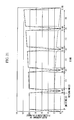
- FIG. 21 is a graph showing the variation of the first electrostrictive element 32A and the second electrostrictive element 32B when the driving operation and the returning operation are repeated.
- the abscissa axis of the graph represents time, and the ordinate axis of the graph represents variation.
- a graph shown by the solid line in the drawing shows the variation of the first electrostrictive element 32A, and a graph shown by the broken line in the drawing shows the variation of the second electrostrictive element 32B.
- the variation of the first electrostrictive element 32A becomes larger as the driving operation (1) and the returning operation (2) are repeated.
- Effective torque N e in this embodiment depends on the time t all taken to perform one cycle of the driving operation and the returning operation, the time t e that is taken until the rotor SF is brought into an inertia state from the start of transmission of the effective tension, a target effective tension T goal , and the radius R of the diameter-enlarged portion 12 of the rotor SF.
- parameters which control the effective torque N e include three, i.e., t all , t e , and T goal . Since the time t all of one cycle of the driving operation and the returning operation is constantly set when performing the driving control of the rotor SF, it is preferable to control the effective torque N e by changing two values, t e and T goal .
- the rotor SF can be dynamically rotated while being accelerated or decelerated by repeating the driving operation which utilizes the elastic deformation of the transmission member BT, makes zero the relative velocity between the outer periphery of the diameter-enlarged portion 12 of the rotor SF, and the transmission member BT, and transmits the effective tension of the transmission member BT to the rotor SF, and the returning operation which moves the first end 22A and the second end 22B simultaneously inward. Additionally, even if the moving part AC is small, it is possible to rotate the rotor SF with high efficiency.
- the motor device MT2 is adapted to make a progressive wave propagate to the transmission member BT wound around the rotor SF, thereby rotating the rotor SF, as shown in FIG. 22 .
- the transmission member BT is wound around the rotor SF in a state where no tension is transmitted.
- the progressive wave is easily propagated by not transmitting tension to the transmission member BT.
- the first end 22A is connected to, for example, a vibration exciter 61
- the second end 22B is connected to, for example, a damper 62.
- the vibration exciter 61 and the damper 62 are connected to the control unit CONT.
- the control unit CONT controls the operation of the vibration exciter 61 and damper 62.
- the control unit CONT makes the vibration exciter 61 driven, and thereby, makes a progressive wave (for example, 42.2kHz) propagate to the transmission member BT.
- a progressive wave for example, 42.2kHz
- the surface of the transmission member BT makes an elliptical motion.
- the rotor SF rotates in a direction opposite to the propagation of the progressive wave.
- control unit CONT drives the damper 62 to change the load resistance provided inside the damper 62, and takes impedance matching to reduce the reflection of the progressive wave in the second end 22B.
- the stationary wave which propagates to the transmission member BT is suppressed.
- the control unit CONT can reverse the propagation of the progressive wave, thereby reversing the rotational direction of the rotor SF.
- the rotor SF can be rotated by making a progressive wave propagate to the transmission member BT. Therefore, even if the motor device is small and if a progressive wave is made to propagate to the transmission member BT, it is possible to transmit high torque to the rotor SF. Additionally, according to this embodiment, it is possible to rotate the rotor SF with high efficiency.
- FIG. 23 is a view showing a configuration to which the motor device MTR is applied to, for example, a robot arm.
- the motor device MTR is connected to a robot arm ARM (arm portion) via a coupling CPL. Since the motor device MTR of the above embodiment is small and is able to output high torque, the robot arm ARM can be driven with high precision. Additionally, the motor device MTR of the above embodiment can be applied to a joint part of a robot (an apparatus), a driving unit of a machine tool (an apparatus), etc.
- the rotor is solid circular cylinder in the above embodiment, the invention is not limited thereto.
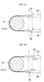
- the rotor SF may be hollow, for example, as shown in FIG. 24A .
- the rotor SF has a through portion 71 passing therethrough in the direction of the rotational axis.
- the through portion 71 is provided with a cylindrical bearing 70.
- the rotor SF is made rotatable around the bearing 70.
- wiring 72, etc. can be arranged inside the bearing 70.
- the rotor SF as a wiring duct.
- the rotation transmission state is a state where there is no slip between the rotor SF and the transmission member BT due to a frictional force
- the invention is not limited thereto.
- the rotation transmission state may be a state where the rotor SF and the transmission member BT are engaged with each other.
- protrusions 15 are provided on the rotor SF
- recesses 25 are provided in the transmission member BT so as to engage with the protrusions 15. In this way, a configuration in which torque is transmitted by engaging the protrusions 15 of the rotor SF with the recesses 25 of the transmission member BT may be adopted.
- a direction in which the protrusions 15 of the rotor SF are provided is not particularly limited, and may be a random direction, the direction of the rotational axis of the rotor SF, the circumferential direction of the rotor SF, etc.
- a configuration in which recesses are provided in the rotor SF, and protrusions are provided on the transmission member BT may be adopted.
- the size of the above protrusions (for example, protrusions 15) or recesses (for example, recesses 25) are not particularly limited.
- the protrusions or recesses are small such that the transmission member BT can be loosened by the moving part AC, or the protrusions or recesses are small such that a gap can be created between the rotor SF and the transmission member BT by the moving part AC.
- the engagement in this embodiment includes, for example, the meshing between the protrusions 15 of the rotor SF and the recesses 25 of the transmission member BT, the fitting between the protrusions 15 of the rotor SF and the recesses 25 of the transmission member BT, the jointing between the protrusions 15 of the rotor SF and the recesses 25 of the transmission member BT, and the protrusions 15 of the rotor SF and the recesses 25 of the transmission member BT do not need to be completely engaged with each other.
- a closed belt structure in which the transmission member BT is wound around the rotor SF by 360° and the crossing portion 21 is provided is adopted in the above embodiment.
- the invention is not limited thereto.
- an open belt structure where the transmission member BT is wound around the rotor SF at an angle of less than 360° may be adopted. In this case, since the transmission member BT can be used for transmission of torque over its whole width, the torque can be efficiently transmitted.
- every transmission member BT may be formed so as to have a different diameter. According to this configuration, since the transmission of torque can be changed for every the transmission member BT, broad driving becomes possible.
- a configuration in which the surface of the rotor SF is flat has been described as an example.
- the invention is not limited thereto.
- a configuration in which the surface of the transmission member BT is flat has been described as an example.
- the invention is not limited thereto.
- a direction in which the grooves of the rotor SF are provided is not particularly limited, and may be a random direction, the direction of the rotational axis of the rotor SF, the circumferential direction of the rotor SF, etc.
- the transmission member BT is formed in the shape of a belt
- the invention is not limited thereto.
- the transmission member may be formed in the shape of a line or a chain.
- tension can be controlled by the displacement of the first electrostrictive element 32A and second electrostrictive element 32B.
- the control of held torque is possible during the stop of driving.
- the moving part AC which moves the transmission member BT has an electrostrictive element
- the invention is not limited thereto.
- a configuration in which the moving part uses other actuators, such as a magnetostrictor, an electromagnet, or a VCM (voice coil motor) may be adopted, instead of the electrostrictive element.
- the magnetostrictor in a case where the magnetostrictor is used, thrust can be increased.
- the electromagnet driving with high thrust and long stroke is possible.
- driving with long stroke is possible, and torque control becomes easy.
- torque is transmitted to the rotor from the transmission member, and the rotor is rotated as the moving part performs the driving operation and the returning operation.
- the transmission member is wound around at least a portion of the rotor which is wrapped in a torque transmission state
- the rotor can be rotated by making a progressive wave propagate to the transmission member. Therefore, even if the motor device is small and if a progressive wave is made to propagate to the transmission member, it is possible to transmit high torque to the rotor.
- torque is transmitted to the rotor from the transmission member, and the rotor is rotated as the moving part performs the driving step operation and the returning step.
- the transmission member is wound around at least a portion of the rotor in a torque transmission state
- torque is uniquely determined by the tension to be transmitted to the transmission member according to the friction belt theory of Euler. Accordingly, even if the motor device is small and if tension can be generated in the transmission member, it is possible to transmit high torque to the rotor.
Landscapes
- General Electrical Machinery Utilizing Piezoelectricity, Electrostriction Or Magnetostriction (AREA)
Applications Claiming Priority (2)
| Application Number | Priority Date | Filing Date | Title |
|---|---|---|---|
| JP2008333925 | 2008-12-26 | ||
| PCT/JP2009/007192 WO2010073668A1 (fr) | 2008-12-26 | 2009-12-24 | Dispositif moteur, dispositif et procédé d'entraînement de rotor |
Publications (2)
| Publication Number | Publication Date |
|---|---|
| EP2372896A1 true EP2372896A1 (fr) | 2011-10-05 |
| EP2372896A4 EP2372896A4 (fr) | 2014-07-30 |
Family
ID=42283983
Family Applications (1)
| Application Number | Title | Priority Date | Filing Date |
|---|---|---|---|
| EP20090834474 Withdrawn EP2372896A4 (fr) | 2008-12-26 | 2009-12-24 | Dispositif moteur, dispositif et procédé d'entraînement de rotor |
Country Status (8)
| Country | Link |
|---|---|
| US (1) | US8674586B2 (fr) |
| EP (1) | EP2372896A4 (fr) |
| JP (1) | JP5541163B2 (fr) |
| KR (1) | KR20110117060A (fr) |
| CN (1) | CN102265500B (fr) |
| BR (1) | BRPI0923487A2 (fr) |
| TW (1) | TW201031106A (fr) |
| WO (1) | WO2010073668A1 (fr) |
Families Citing this family (6)
| Publication number | Priority date | Publication date | Assignee | Title |
|---|---|---|---|---|
| JP5835212B2 (ja) * | 2010-03-31 | 2015-12-24 | 株式会社ニコン | モータ装置、モータ装置の製造方法及びロボット装置 |
| JP6415853B2 (ja) * | 2014-05-23 | 2018-10-31 | オリンパス株式会社 | 光調節装置 |
| US10029366B2 (en) * | 2014-11-21 | 2018-07-24 | Canon Kabushiki Kaisha | Control device for motor drive device, control device for multi-axial motor, and control method for motor drive device |
| FR3029365B1 (fr) * | 2014-12-01 | 2016-12-23 | Sagem Defense Securite | Procede de detection d'un blocage d'un rotor d'un moteur entrainant un organe d'actionnement |
| CN105205912A (zh) * | 2015-09-30 | 2015-12-30 | 昆山古鳌电子机械有限公司 | 一种纸币交易装置 |
| US10148199B1 (en) * | 2017-05-15 | 2018-12-04 | Baoxiang Shan | Loop-band devices configured for motion |
Family Cites Families (10)
| Publication number | Priority date | Publication date | Assignee | Title |
|---|---|---|---|---|
| DD203191A1 (de) * | 1982-02-05 | 1983-10-12 | Anger Hans Holger | Piezoelektrischer schlingfedervibroantrieb |
| JPH02261073A (ja) | 1989-03-29 | 1990-10-23 | Sony Corp | 超音波モータ |
| JPH02311237A (ja) | 1989-05-25 | 1990-12-26 | Fuji Electric Co Ltd | 搬送装置 |
| JP3487517B2 (ja) | 1993-12-16 | 2004-01-19 | 株式会社リコー | 往復移動装置 |
| EP2568595A3 (fr) * | 1998-12-21 | 2013-05-15 | Seiko Epson Corporation | Actionneur piézo-électrique, compteur de temps et dispositif portable |
| DE50014572D1 (de) | 1999-11-29 | 2007-09-27 | Miniswys Sa | Piezoelektrischer antrieb |
| GB2369489B (en) * | 2000-11-23 | 2004-03-10 | Khaled Karrai | Inertial rotation device |
| US7166953B2 (en) * | 2001-03-02 | 2007-01-23 | Jon Heim | Electroactive polymer rotary clutch motors |
| DE10117465A1 (de) * | 2001-04-06 | 2002-10-10 | Hans Richter | Piezoelektrischer Antrieb |
| JP4422721B2 (ja) * | 2004-05-21 | 2010-02-24 | 正 守屋 | 進行波型超音波モータ |
-
2009
- 2009-12-22 US US12/654,546 patent/US8674586B2/en not_active Expired - Fee Related
- 2009-12-24 JP JP2010543886A patent/JP5541163B2/ja not_active Expired - Fee Related
- 2009-12-24 EP EP20090834474 patent/EP2372896A4/fr not_active Withdrawn
- 2009-12-24 CN CN200980152249.1A patent/CN102265500B/zh not_active Expired - Fee Related
- 2009-12-24 WO PCT/JP2009/007192 patent/WO2010073668A1/fr not_active Ceased
- 2009-12-24 KR KR1020117014494A patent/KR20110117060A/ko not_active Withdrawn
- 2009-12-24 BR BRPI0923487A patent/BRPI0923487A2/pt not_active IP Right Cessation
- 2009-12-25 TW TW098144879A patent/TW201031106A/zh unknown
Also Published As
| Publication number | Publication date |
|---|---|
| JP5541163B2 (ja) | 2014-07-09 |
| EP2372896A4 (fr) | 2014-07-30 |
| WO2010073668A1 (fr) | 2010-07-01 |
| CN102265500B (zh) | 2015-11-25 |
| KR20110117060A (ko) | 2011-10-26 |
| US8674586B2 (en) | 2014-03-18 |
| BRPI0923487A2 (pt) | 2018-05-29 |
| JPWO2010073668A1 (ja) | 2012-06-07 |
| TW201031106A (en) | 2010-08-16 |
| US20100164326A1 (en) | 2010-07-01 |
| CN102265500A (zh) | 2011-11-30 |
Similar Documents
| Publication | Publication Date | Title |
|---|---|---|
| EP2372896A1 (fr) | Dispositif moteur, dispositif et procédé d'entraînement de rotor | |
| US8638024B2 (en) | Actuator | |
| KR102127215B1 (ko) | 와이어 연결 장치 | |
| US8796905B2 (en) | Motor device, method of manufacturing motor device, and robot device | |
| HK1159336A (en) | Motor device, device, and method of driving rotor | |
| US7671513B2 (en) | Piezoelectric motor allowing at least two degrees of freedom, in rotation and linear displacement | |
| US5530312A (en) | Multi-cycle electric motor system | |
| CN116345949B (zh) | 基于三相驱动的旋转型压电电机及其工作方法 | |
| JP2013013218A (ja) | 圧電アクチュエーターの駆動方法 | |
| JPS6323570A (ja) | 回転アクチユエ−タ | |
| US20110241484A1 (en) | Motor device, method of manufacturing motor device, and robot device | |
| JP2010259182A (ja) | モータ装置、回転子の駆動方法及び軸部材の駆動方法 | |
| JPWO2011125719A1 (ja) | モータ装置及び回転子の駆動方法並びにロボット装置 | |
| US9252686B2 (en) | Drive control apparatus and drive control method for vibration wave driving apparatus | |
| JP3830028B2 (ja) | ワイヤーアクチュエータ | |
| JP2011217490A (ja) | モータ装置、回転子の駆動方法及びロボット装置 | |
| JP2014075955A (ja) | 駆動装置、ロボット装置及び露光装置 | |
| US9401667B2 (en) | Vibration-type driving device | |
| JP5825833B2 (ja) | 駆動制御方法、雲台装置およびステージ | |
| JP2008280978A (ja) | スクロール流体機械 | |
| Nishibori et al. | Driving characteristics of robot hand with fingers using Langevin-type ultrasonic motors | |
| Toyama et al. | Mesh robot developed by micro ultrasonic motor | |
| JP2012005201A (ja) | モータ装置及び回転子の駆動方法並びにロボット装置 | |
| JP2024120660A (ja) | アクチュエータ及びアクチュエータの制御方法 | |
| JPH0984368A (ja) | 圧電モータ |
Legal Events
| Date | Code | Title | Description |
|---|---|---|---|
| PUAI | Public reference made under article 153(3) epc to a published international application that has entered the european phase |
Free format text: ORIGINAL CODE: 0009012 |
|
| 17P | Request for examination filed |
Effective date: 20110622 |
|
| AK | Designated contracting states |
Kind code of ref document: A1 Designated state(s): AT BE BG CH CY CZ DE DK EE ES FI FR GB GR HR HU IE IS IT LI LT LU LV MC MK MT NL NO PL PT RO SE SI SK SM TR |
|
| DAX | Request for extension of the european patent (deleted) | ||
| REG | Reference to a national code |
Ref country code: HK Ref legal event code: DE Ref document number: 1159336 Country of ref document: HK |
|
| A4 | Supplementary search report drawn up and despatched |
Effective date: 20140702 |
|
| RIC1 | Information provided on ipc code assigned before grant |
Ipc: H02N 2/16 20060101ALI20140626BHEP Ipc: H02N 2/10 20060101AFI20140626BHEP |
|
| 17Q | First examination report despatched |
Effective date: 20150519 |
|
| RAP1 | Party data changed (applicant data changed or rights of an application transferred) |
Owner name: NIKON CORPORATION |
|
| STAA | Information on the status of an ep patent application or granted ep patent |
Free format text: STATUS: THE APPLICATION IS DEEMED TO BE WITHDRAWN |
|
| 18D | Application deemed to be withdrawn |
Effective date: 20151201 |
|
| REG | Reference to a national code |
Ref country code: HK Ref legal event code: WD Ref document number: 1159336 Country of ref document: HK |