EP2374429B1 - Agencement de montage doté d'un dispositif d'aide et d'un bracket orthodontique - Google Patents
Agencement de montage doté d'un dispositif d'aide et d'un bracket orthodontique Download PDFInfo
- Publication number
- EP2374429B1 EP2374429B1 EP10159393.7A EP10159393A EP2374429B1 EP 2374429 B1 EP2374429 B1 EP 2374429B1 EP 10159393 A EP10159393 A EP 10159393A EP 2374429 B1 EP2374429 B1 EP 2374429B1
- Authority
- EP
- European Patent Office
- Prior art keywords
- bracket
- aid
- slot
- guide grooves
- legs
- Prior art date
- Legal status (The legal status is an assumption and is not a legal conclusion. Google has not performed a legal analysis and makes no representation as to the accuracy of the status listed.)
- Not-in-force
Links
Images


Classifications
-
- A—HUMAN NECESSITIES
- A61—MEDICAL OR VETERINARY SCIENCE; HYGIENE
- A61C—DENTISTRY; APPARATUS OR METHODS FOR ORAL OR DENTAL HYGIENE
- A61C7/00—Orthodontics, i.e. obtaining or maintaining the desired position of teeth, e.g. by straightening, evening, regulating, separating, or by correcting malocclusions
- A61C7/12—Brackets; Arch wires; Combinations thereof; Accessories therefor
- A61C7/14—Brackets; Fixing brackets to teeth
- A61C7/146—Positioning or placement of brackets; Tools therefor
Definitions
- the present invention relates to a mounting arrangement in the correction of misalignment with the aid of orthodontic brackets, in particular a tool and an associated orthodontic bracket.
- brackets that are glued to the teeth of the patient's lower or upper jaw in predefined positions and then connected to each other by means of an elastic wire arch.
- the brackets are applied to the individual teeth in a position which is chosen so that at the end of the orthodontic treatment of the extending through the brackets Richtdrahtbogen is substantially free of waves.
- the directional wire has a very complex course, depending on the malposition of the teeth, the relatively large archwire that follows the mandibular arch, more or less wavy in and out of the plane described by him.
- the brackets are to be glued to the teeth.
- the first approach the so-called direct procedure, the patient's teeth are measured optically without imprinting using suitable measuring tools.
- a "manual" method in which the measured values are recorded and evaluated by hand, or a computer-aided method alternatively used.
- the recorded measurements are processed by a computer program that not only determines the bracket positions, but also controls a wire bending machine, with a set of straightening wires of different cross sections, which in the course of treatment on the patient used sequentially used, each in a relatively complicated Shapes that take into account the individual malposition of the teeth.
- This technique is particularly used when lingual, ie, to the tongue side, brackets are to be used because the tooth forms on the lingual side are very different from individual to individual. There one can not orient oneself on the outline of the tooth crown, in contrast to the crown image on the labial, ie the outer, turned to the lips side, on which the teeth exhibit largely coincident forms despite the individuality of humans.
- the second, more common approach to determining the bracket positions on the teeth is the so-called Hiro technique.
- the orthodontist first makes an impression of the denture to be corrected. From this impression, a plaster cast of the denture to be corrected is produced in the dental laboratory. This casting is sawn into the individual teeth and reassembled using wax to create the perfect bite or occlusion that orthodontic treatment should achieve. Thereafter, the directional arch is created, brackets are applied to the archwire, and the arch, together with the brackets, is positioned on the lingual side of the corrected cast such that the brackets are in a prescribed manner against the teeth, with between the brackets and the teeth a certain distance is maintained, which is to be filled later with a potting compound.
- the orthodontist's set of brackets are glued to the associated teeth of the denture to be corrected using a thin film of adhesive, the copings again serving as gauges that position the brackets on the teeth exactly as they are positioned on the corrected plaster cast were.
- the adhesive has cured, the copings are broken away, which is a time-consuming task because the acrylic material must be completely removed from the brackets.
- a disadvantage of both approaches is that after unintentionally releasing a bracket from a tooth during the entire orthodontic corrective treatment, it is difficult to correctly reposition the bracket in question to the tooth. This work can only be done using the laboratory.
- a new set of wires is required for "manual" or computer surveying, and a new set of wires must be made because the patient usually can not immediately visit his orthodontist and reset the tooth position correction in the meantime.
- the unintentional release of a bracket is not so rare. It usually occurs in each patient once during the treatment period.
- a new custom base including an acrylic cap needs to be fabricated from the labyrinth wire in the laboratory for a new bracket.
- a mounting aid is proposed to remedy the above-mentioned disadvantages consisting of a metal strip, the means for positive engagement with the bracket, a holding device for anchoring an elastic tensioning device on the metal strip for fixing the Sheet metal strip on the bracket and extending away from the holding device has flag.
- the further processing then provides in the usual way the creation of the individual base on each bracket.
- the bracket set thus completed, together with the mounting aids embedded in the copings, are made available to the orthodontist, who places the brackets on the missing teeth.
- the coping with the mounting aids adhering thereto thus form mounting gauges for the attachment of the brackets in predetermined positions on the teeth in which the Orthodontic brackets are adhered to the teeth using a thin film of adhesive.
- the orthodontist releases the mounting jigs from the brackets. It is not necessary to destroy anything.
- the orthodontist usually disassembles the individually labeled mounting jigs so that he can later use them again, if necessary, because a bracket has become detached from a tooth.
- the device for the assembly of orthodontic brackets which is formed from a strip of material, a first end and a second end having means for positive engagement with the bracket, wherein the means for positive engagement comprise two legs, the fork-like extend the second end and the longitudinal sides are substantially parallel to each other, wherein the aid has a slot where the two legs extend from the central body.
- an orthodontic bracket with a base plate, the a bottom for attachment to a tooth and a top, and an upwardly extending structure having at least two vanes, between which a slot for receiving a directional wire extends, the structure laterally each having a guide groove for pushing an aid, the essentially parallel to each other.
- the two elements form according to the invention a mounting arrangement for mounting an orthodontic bracket to a tooth, wherein the mounting aid releasably connected to the orthodontic bracket form-fitting by pushing together by intervene by pushing the long sides of the legs of the mounting tool in the guide grooves of the bracket.
- the assembly aid can act both on the outside of the bracket structure and on the inside of the bracket structure, provided that the corresponding side surfaces of the bracket structure are suitable for receiving the longitudinal sides of the legs of the auxiliary device.
- these can be the inner longitudinal sides or the outer longitudinal sides of the legs.
- the handling in the first adjustment and optionally in the subsequent attachment of lingual and buccal brackets is very easy.
- additional elements such as clamping rings or similar. and to dispense with additional tools. Due to the positive and yet releasable connection a very exact positioning of the bracket is possible.
- the simple design of the mounting tool saves material compared to previous solutions and offers a high degree of flexibility, because the production costs of mounting tools of different sizes for different bracket widths, which are usually between about 2 mm and 5 mm, are low.
- a pave width ie the distance between the parallel longitudinal sides of the legs of about 0.05 mm to 0.1 mm less than the width of the bracket, optionally taking into account the depth of the guide grooves, optimum results in terms of Handling and fixation supplies.
- a pave width ie the distance between the parallel longitudinal sides of the legs of about 0.05 mm to 0.1 mm less than the width of the bracket, optionally taking into account the depth of the guide grooves
- the mounting aid is formed axially symmetrical and the slot extends substantially along and on the axis of symmetry extending from the first to the second end.
- a mounting tool made of sheet metal having a thickness of about 0.15 mm to about 0.8 mm. Furthermore, it is preferred if the slot has a length of about 1.0 mm to about 5.0 mm and a width of about 0.1 mm to about 0.8 mm.
- At least one leg has at least one recess.
- the legs at each end have a circular recess into which a spreading forceps can engage to assist in the attaching or detaching process.
- the shape of the recess may have a purposefully different configuration, e.g. a square, elliptical or polygonal etc.
- the first end may preferably have at least one recess, so that there also with a suitable tool such. can attack a pair of pliers to bend the first end. This usually a better fixation of the copings is achieved. A broadening of the first end can also be advantageous.
- the slot has a widened portion at its closed end.
- the shape of the widened portion may be e.g. be round, elliptical or polygonal.
- a connection between the assembly aid and the bracket can also be effected effectively if the bracket has no guide grooves laterally, but only two parallel side surfaces on which the longitudinal sides of the legs of the assembly aid can engage.
- the guide grooves are not quite straight, but slightly curved, but parallel to each other, are formed. In other words, it is particularly important that the guide grooves on the bracket parallel to each other, but the Relative arrangement relative to the bottom of the bracket is flexible. This offers a flexibility that is necessary because of particularly strong tooth misalignments or other geometric requirements.
- Fig. 1 shows in plan view a first embodiment of an aid 10 according to the invention in a greatly enlarged scale.
- the components used for the invention Monatagean extract, ie, the mounting aid according to the invention and the bracket according to the invention are relatively small components, and accordingly, all components shown in the figures in greatly enlarged scale are very small.
- the total length of the mounting tool 10 is for example about 10 mm, the largest width is about 5 mm, correspondingly dimensioned are the remaining details of the component.
- the mounting tool 10 is made of a metal strip of about 0.2 mm thickness.
- the mounting tool 10 is formed axially symmetrical with respect to a central axis extending from the first end 11 to the second end 12.
- the second end 12 has two substantially equal length, parallel legs 13, each having inner longitudinal sides 14 which are parallel to each other.
- a slot 15 which has a width of about 0.5 mm and a length of about 2.3 mm in the illustrated embodiment.
- the first end 11 is slightly widened with respect to the middle part and has in the middle two round recesses 16 into which, for example, a tool can engage.
- the width of the mounting tool 10 is greater at its second end 12 than at its first end eleventh
- Fig. 2 shows in side view the mounting tool 10 Fig. 1 , It recognizes the relatively thin metal strip, which can be relatively easily produced, for example, by punching, cutting, milling or sawing from the sheet material.
- Figure 3 shows a plan view of a mounting aid according to the invention according to a second embodiment.
- the configuration of the first end 11 is substantially identical to the configuration of the mounting tool Fig. 1
- the shape of the legs 13 is different. It can be seen that the legs 13 have a curved shape on their outer side and each have a round recess 17 at its end. In these recesses 17, a spreading forceps or a similar tool can engage to move the legs apart and thus to assist in pushing or separating a bracket.
- the shape of the recess 17 does not have to be round - other suitable configurations such as elliptical, rectangular, polygonal, etc. may also be provided.
- Fig. 4 shows a plan view of a mounting aid according to the invention according to a further embodiment, wherein the second end 12 on both sides of the slot 15 each have a recess 17 into which a spreading forceps can engage as described above.
- the recesses 17 not positioned at the end of the legs 13, but in the direction of the center part of the mounting tool. This means due to the different levers a higher force that is applied for the bending apart of the two legs 13 by means of a spreading forceps.
- Fig. 5 shows a plan view of a per se known bracket 20, which, however, can be combined with the mounting aid 10 according to the invention under certain conditions to a mounting arrangement according to the invention for brackets.
- the bracket 20 includes a base plate 21, the bottom 22 is adhered to the tooth. From the upper side 23 of the base plate 21 extends a structure 24 which has a slot 25 for receiving a directional wire.
- the structure comprises two first wing halves 26 and two second wing halves 27, between which is located both the mentioned slot 25 for the directional wire and a space perpendicular to the slot.
- Decisive for the inventive cooperation between mounting aid and bracket is the configuration of the outer or side edges of the structure 24 vertically to the direction of the slot 25. If the two side edges of the structure 24 are parallel to each other and have a substantially planar surface, the bracket is suitable to be fixed by the mounting tool 10, as described below with reference to Fig. 8 is described.
- Fig. 6 shows a plan view of a bracket according to the invention, which in principle has the same structure 20 with the same elements as the known per se bracket after
- lateral flanks of the assembly 24 each have a guide groove 28 which are parallel to each other and substantially straight, so that the mounting tool 10 engage exactly in the guide grooves according to Arte wrench and on the bracket 20th can be postponed as with reference to the below FIGS. 9 and 10 is described.
- Fig. 7 shows the embodiment of the bracket Fig. 6 in side view, here clearly the slot 25 and the guide grooves 28 can be seen.
- the width and the depth of the guide grooves 28 must be structured such that a trouble-free sliding of the mounting tool 10, a sufficient support and also a removal of the mounting tool 10 is made possible by the bracket 20.
- Fig. 8, 9 show in plan view a mounting arrangement according to the invention with the brackets from the Fig. 5 6 and the assembly aid 10 of the embodiment according to Fig. 1 ,
- Fig. 8 it can be seen how the assembly aid 10 engages around the structure 24 of the bracket 20 in a form-fitting manner along the inner longitudinal sides 14 of the legs 13.
- the slot 15 of the mounting tool 10 is thereby expanded, taking into account the elasticity of the sheet material by a small distance to the opening, so that there is sufficient clamping and fixation.
- the bracket in the embodiment according to Fig. 8 has no lateral guide grooves, the connection is not quite as accurate as in the embodiments with guide grooves (see Fig. 9 below), because at least theoretically, the inner longitudinal sides 14 of the legs 13 could wedge something, so that the orientation of the mounting tool 10 in Aufschiebbene not exactly vertical to the profile of the lateral flanks of the structure 24 of the bracket 20.
- FIGS. 9 and 10 show in plan or side view of the mounting arrangement according to the invention consisting of the mounting tool 10 and the bracket after Fig. 6 or 7.
- the fixation or connection between mounting tool and bracket is better in this embodiment shown here as in the embodiment according to Fig. 8 because the guide grooves 28 provide for an exact guidance and thus positioning of the inner longitudinal sides 14 of the legs 13 of the mounting aid 10 on the lateral flanks of the structure 24 of the bracket 20.
- Fig. 11 shows in plan view a further preferred embodiment of the aid according to the invention. Since the majority of elements are essentially identical to those in terms of in Fig. 1 are described elements illustrated embodiment, will be discussed here only on the differences. The main difference is that the legs 13 arranged at the second end 12 of the mounting aid 10 extend in the extension of the slot 15. The two legs 13 are not in the embodiment of the type of open-end wrench, but more like a thin fork. This can bring advantages in handling, because the required volume is smaller than in the embodiments discussed above.
- the aid 10 off Fig. 11 the slot 15 at its closed end on a widened portion 18 in the form of a circle, in which a tool can engage.
- the legs 13 in this embodiment have on their outer side longitudinal sides 14, which are parallel to each other. The inner long sides form the boundary of the slot 15th
- Fig. 12 shows the mounting tool 10 in side view.
- the thickness of the sheet material is about 0.25 mm.
- Fig. 13 can be seen in plan view an inventive bracket 20, which together with the mounting tool Fig. 11 in the Fig. 15 illustrated mounting arrangement according to another embodiment of the invention forms.
- the essential components of the bracket 20 are identical to those with respect to Fig. 6 described, with the difference is that the guide grooves 28 are not arranged on the outer surfaces of the structure 24, but on the inner surfaces, here perpendicular to the slot 25. It should be understood that in the structure 24 shown in this embodiment, the gap between each of the first and second wing halves 26 and 27 must be so deep that the guide grooves 28 can be mounted therein.
- Fig. 14 shows the bracket Fig. 13 in cross-sectional view.
- FIGS. 15 and 16 show the assembled to a mounting assembly according to the invention components 10 and bracket 20 in plan or cross-sectional view. It can be seen well how the aid 10 is located inside the structure 24 of the bracket and the longitudinal sides 14 of the legs 13 engage in the guide grooves 28 and thereby produce the necessary fixation. Again, it is true that the bracket 20 does not necessarily have guide grooves 28 on the structure, but only parallel inner surfaces on the structure 24th
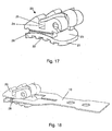
- Fig. 18 and 19 show in perspective view a mounting arrangement according to the invention in different positions of the mounting tool on the bracket 20th
- Fig. 17 shows a bracket according to the invention in a further embodiment, wherein the per se known bracket construction for the operation of the present invention is not critical. Shown in the 17 to 19 a bracket assembly with a spring element with which the straightening wire is fixed in the slot 25.
- the lateral flanks of the structure 24 have substantially parallel surfaces and best exactly parallel guide grooves 28 in order to guide the longitudinal sides 14 of the legs 13 of the assembly aid exactly.
- the present invention provides a combination of an assembly tool and a bracket that is very easy to handle, design, and manufacture, at the same time providing an accurate and strong connection between the two elements, requiring little material, and for a variety of brackets available on the market is flexible.
Landscapes
- Health & Medical Sciences (AREA)
- Oral & Maxillofacial Surgery (AREA)
- Dentistry (AREA)
- Epidemiology (AREA)
- Life Sciences & Earth Sciences (AREA)
- Animal Behavior & Ethology (AREA)
- General Health & Medical Sciences (AREA)
- Public Health (AREA)
- Veterinary Medicine (AREA)
- Dental Tools And Instruments Or Auxiliary Dental Instruments (AREA)
Claims (13)
- Outil (10) pour le montage de brackets orthodontiques, qui est formé d'une bande de matériau, comprenant une première extrémité (11) et une deuxième extrémité (12), qui présente des dispositifs à installer par complémentarité de forme sur le bracket,
caractérisé en ce
que les dispositifs à installer par complémentarité de forme comprennent deux branches (13) qui s'étendent à la manière d'une fourche à la deuxième extrémité (12) et dont les côtés longitudinaux (14) des branches (13) sont essentiellement parallèles les uns aux autres, l'outil (10) présentant une fente (15) entre les deux branches (13). - Outil (10) selon la revendication 1, caractérisé en ce que l'outil est réalisé de manière axisymétrique, et en ce que la fente (15) s'étend essentiellement le long de l'axe de symétrie et sur ce dernier.
- Outil (10) selon l'une des revendications précédentes, caractérisé en ce que l'outil est formé d'une tôle présentant une épaisseur d'environ 0,15 mm à environ 0,8 mm.
- Outil (10) selon l'une des revendications précédentes, caractérisé en ce que la fente (15) présente une longueur d'environ 1,0 mm à environ 5,0 mm et une largeur d'environ 0,1 mm à environ 0,8 mm.
- Outil (10) selon l'une des revendications précédentes, caractérisé en ce qu'au moins une branche (13) présente au moins un évidement (17).
- Outil (10) selon l'une des revendications précédentes, caractérisé en ce que la fente (15) présente en son extrémité fermée une section (18) élargie.
- Outil (10) selon l'une des revendications précédentes, caractérisé en ce que la première extrémité (11) présente au moins un évidement (16).
- Outil (10) selon l'une des revendications précédentes, caractérisé en ce que la première extrémité (11) présente un élargissement.
- Bracket (20) orthodontique comprenant une plaque de base (21) qui présente un côté inférieur (22) à fixer sur une dent et un côté supérieur (23), et présentant une structure (24) s'étendant sur le côté supérieur (23) pourvue d'au moins deux ailettes (26, 27) entre lesquelles s'étend la fente (25) servant à recevoir un fil de redressement,
caractérisé en ce
que la structure (24) présente sur les côtés deux rainures de guidage (28) servant à enfiler un outil (10), lesquelles s'étendent essentiellement de manière parallèle l'une à l'autre, et en ce que les rainures de guidage (28) sont disposées respectivement dans la zone entre la fente (25) et la plaque de base (21). - Bracket (20) selon la revendication 9, caractérisé en ce que les rainures de guidage (28) sont réalisées extérieurement sur la structure (24).
- Bracket (20) selon la revendication 9, caractérisé en ce que les rainures de guidage (28) sont réalisées intérieurement sur la structure (24), de telle manière que les rainures de guidage se fassent face.
- Bracket (20) selon l'une des revendications 9 à 11, caractérisé en ce que les rainures de guidage (28) sont rectilignes ou légèrement incurvées.
- Ensemble de montage pour le montage d'un bracket orthodontique sur une dent, comprenant
un outil (10) selon l'une des revendications 1 à 8, et
un bracket (20) orthodontique selon l'une des revendications 9 à 12,
l'outil (10) pouvant être relié de manière amovible au bracket (20) orthodontique par complémentarité de forme par enfilage l'un sur l'autre, tandis que les côtés longitudinaux (14) des branches (13) de l'outil (10) viennent en prise avec les rainures de guidage (28) du bracket (20) par enfilage.
Priority Applications (4)
| Application Number | Priority Date | Filing Date | Title |
|---|---|---|---|
| EP10159393.7A EP2374429B1 (fr) | 2010-04-08 | 2010-04-08 | Agencement de montage doté d'un dispositif d'aide et d'un bracket orthodontique |
| US13/074,424 US20110250556A1 (en) | 2010-04-08 | 2011-03-29 | Mounting Arrangement with Mounting Aid and Orthodontic Bracket |
| CN2011100907231A CN102138829A (zh) | 2010-04-08 | 2011-04-01 | 带安装辅具的口腔正畸托安装结构 |
| JP2011084205A JP2011218166A (ja) | 2010-04-08 | 2011-04-06 | 取付補助具及び歯科矯正ブラケットを備えた取付構造 |
Applications Claiming Priority (1)
| Application Number | Priority Date | Filing Date | Title |
|---|---|---|---|
| EP10159393.7A EP2374429B1 (fr) | 2010-04-08 | 2010-04-08 | Agencement de montage doté d'un dispositif d'aide et d'un bracket orthodontique |
Publications (2)
| Publication Number | Publication Date |
|---|---|
| EP2374429A1 EP2374429A1 (fr) | 2011-10-12 |
| EP2374429B1 true EP2374429B1 (fr) | 2014-11-19 |
Family
ID=42651097
Family Applications (1)
| Application Number | Title | Priority Date | Filing Date |
|---|---|---|---|
| EP10159393.7A Not-in-force EP2374429B1 (fr) | 2010-04-08 | 2010-04-08 | Agencement de montage doté d'un dispositif d'aide et d'un bracket orthodontique |
Country Status (4)
| Country | Link |
|---|---|
| US (1) | US20110250556A1 (fr) |
| EP (1) | EP2374429B1 (fr) |
| JP (1) | JP2011218166A (fr) |
| CN (1) | CN102138829A (fr) |
Families Citing this family (31)
| Publication number | Priority date | Publication date | Assignee | Title |
|---|---|---|---|---|
| USD654594S1 (en) * | 2007-02-07 | 2012-02-21 | Under Dog Media, L.P. | Orthodontic attachment plate device |
| FR2959929B1 (fr) | 2010-05-17 | 2012-07-20 | H 32 | Gabarit individualise pour appareillage orthodontique, ensemble forme par ce gabarit, une base et une attache, et ses procedes de conception. |
| FR2992162B1 (fr) * | 2012-06-21 | 2017-06-16 | Arnaud Lac-Beriere | Appareillage d'orthodontie ou d'orthopedie dento-faciale ameliore, en particulier pour une propulsion mandibulaire |
| ES2874777T3 (es) | 2012-10-30 | 2021-11-05 | Univ Southern California | Aparato de ortodoncia con arco de alambre encajado a presión, antideslizante |
| US9707056B2 (en) | 2013-03-06 | 2017-07-18 | American Orthodontics Corporation | Indirect bonding tray and method of manufacture thereof |
| US20150024332A1 (en) * | 2013-07-22 | 2015-01-22 | Bachar TAHA | Anchor plate in orthodontics |
| CA2955936C (fr) | 2013-09-20 | 2017-09-12 | Brandon OWEN | Systeme de boitier |
| US20180161126A1 (en) * | 2013-12-16 | 2018-06-14 | American Orthodontics Corporation | Orthodontic Bonding Guide |
| CN104083224B (zh) | 2014-07-04 | 2017-04-05 | 谭荣基 | 自动化口腔正畸托槽定位系统 |
| CN117695035A (zh) | 2016-04-18 | 2024-03-15 | 斯威夫特健康系统有限公司 | 具有非滑动的绑扎弓丝的牙齿正畸矫正器 |
| US20170325911A1 (en) * | 2016-05-12 | 2017-11-16 | American Orthodontics Corporation | Bonding Guide with Living Hinge Pins |
| US10828133B2 (en) | 2016-12-02 | 2020-11-10 | Swift Health Systems Inc. | Indirect orthodontic bonding systems and methods for bracket placement |
| CN115024842B (zh) | 2017-01-31 | 2025-01-28 | 斯威夫特健康系统有限公司 | 混合正畸弓丝 |
| US11612458B1 (en) * | 2017-03-31 | 2023-03-28 | Swift Health Systems Inc. | Method of tongue preconditioning in preparation for lingual orthodontic treatment |
| CN110740704B (zh) | 2017-04-21 | 2021-10-29 | 斯威夫特健康系统有限公司 | 间接粘接托盘、非滑动正畸矫正器和使用其的配准系统 |
| EP3427691B1 (fr) * | 2017-07-14 | 2019-12-04 | W & H Dentalwerk Bürmoos GmbH | Unité de traitement de prophylaxie dentaire |
| US10575928B2 (en) | 2017-09-21 | 2020-03-03 | Brandon Owen | Orthodontic bracket retention anchor |
| US11331165B2 (en) | 2018-03-27 | 2022-05-17 | Klowen Braces, Inc. | Orthodontic treatment system |
| US11123159B2 (en) | 2018-07-16 | 2021-09-21 | Brandon Owen | Orthodontic bracket identification mark |
| US11291527B2 (en) | 2018-09-28 | 2022-04-05 | IDM Tooling, LLC | Tool for seating an orthodontic aligner and method of using same |
| US20200275996A1 (en) | 2019-03-01 | 2020-09-03 | Swift Health Systems Inc. | Indirect bonding trays with bite turbo and orthodontic auxiliary integration |
| USD910176S1 (en) | 2019-08-06 | 2021-02-09 | IDM Tooling, LLC | Tool for seating and removing an orthodontic aligner |
| CN114727853B (zh) | 2019-10-31 | 2024-10-01 | 斯威夫特健康系统有限公司 | 间接正畸粘合系统和方法 |
| CN116075279A (zh) | 2020-06-11 | 2023-05-05 | 斯威夫特健康系统公司 | 具有非滑动弓形件的正畸矫正器 |
| US10945816B1 (en) | 2020-07-08 | 2021-03-16 | King Saud University | Orthodontic bracket positioning instrument |
| CN112006793B (zh) * | 2020-08-21 | 2022-01-14 | 南京医科大学附属口腔医院 | 一种球囊水压型牙齿矫正装置 |
| EP4046588B1 (fr) * | 2021-02-23 | 2024-06-19 | LYS Office | Jauge de positionnement de hauteur orthodontique |
| US12268571B2 (en) | 2021-03-12 | 2025-04-08 | Swift Health Systems Inc. | Indirect orthodontic bonding systems and methods |
| WO2023033870A1 (fr) | 2021-09-03 | 2023-03-09 | Swift Health Systems Inc. | Procédé d'administration d'adhésif pour collage de verrous orthodontiques |
| US12193908B2 (en) | 2021-09-03 | 2025-01-14 | Swift Health Systems, Inc. | Orthodontic appliance with non-sliding archform |
| USD1043994S1 (en) | 2022-01-06 | 2024-09-24 | Swift Health Systems Inc. | Archwire |
Family Cites Families (17)
| Publication number | Priority date | Publication date | Assignee | Title |
|---|---|---|---|---|
| US3521355A (en) * | 1969-06-30 | 1970-07-21 | Lawrence Pearlman | Positioning means for orthodontic brackets |
| US3657817A (en) * | 1970-05-18 | 1972-04-25 | Peter C Kesling | Holder for an orthodontic bracket |
| US4626208A (en) * | 1985-08-16 | 1986-12-02 | Tp Orthodontics, Inc. | Positioning jig for edgewise bracket |
| US5064369A (en) * | 1987-01-27 | 1991-11-12 | Tomy, Inc. | Orthodontic device |
| US4904183A (en) * | 1987-05-08 | 1990-02-27 | Unitek Corporation | Orthodontic debonding method and tool |
| JPH02149265A (ja) * | 1988-11-30 | 1990-06-07 | Morita Tokyo Seisakusho:Kk | 歯科矯正用ブラケット |
| US5035612A (en) * | 1990-05-02 | 1991-07-30 | Johnson & Johnson Consumer Products, Inc. | Debonding tip for electrothermal dental bracket removal |
| US5542842A (en) * | 1992-11-09 | 1996-08-06 | Ormco Corporation | Bracket placement jig assembly and method of placing orthodontic brackets on teeth therewith |
| JPH06189814A (ja) * | 1992-12-25 | 1994-07-12 | Musashi Koeki Kk | 腕時計バンドの中留装置の製造方法 |
| CA2139078C (fr) * | 1993-12-23 | 1998-04-21 | James A. Nicholson | Supports orthodontiques |
| US7094053B2 (en) * | 2002-05-28 | 2006-08-22 | Ormco Corporation | Custom jig for placing orthodontic brackets and methods of making and using same |
| DE50202544D1 (de) * | 2002-06-20 | 2005-04-28 | Schendell Groeling Claus | Montagehilfsmittel für die Befestigung eines kieferorthopädischen Bracket |
| US7419375B2 (en) * | 2002-08-19 | 2008-09-02 | Ormco Corporation | Aesthetic self-ligating orthodontic bracket |
| US7621743B2 (en) * | 2002-11-26 | 2009-11-24 | Orthodontic Research And Development, S.L. | Orthodontic bracket |
| US20080138756A1 (en) * | 2004-04-01 | 2008-06-12 | Innobrace Orthodontics Pte Ltd | Orthondontic Bracket With Mesial And Distal Tie Wing Undercuts |
| US7267545B2 (en) * | 2005-01-11 | 2007-09-11 | Ormco Corporation | Self-ligating orthodontic bracket |
| US20060228662A1 (en) * | 2005-04-08 | 2006-10-12 | Lokar Robert R | Low profile self-ligating bracket assembly and method of use |
-
2010
- 2010-04-08 EP EP10159393.7A patent/EP2374429B1/fr not_active Not-in-force
-
2011
- 2011-03-29 US US13/074,424 patent/US20110250556A1/en not_active Abandoned
- 2011-04-01 CN CN2011100907231A patent/CN102138829A/zh active Pending
- 2011-04-06 JP JP2011084205A patent/JP2011218166A/ja active Pending
Also Published As
| Publication number | Publication date |
|---|---|
| US20110250556A1 (en) | 2011-10-13 |
| EP2374429A1 (fr) | 2011-10-12 |
| CN102138829A (zh) | 2011-08-03 |
| JP2011218166A (ja) | 2011-11-04 |
Similar Documents
| Publication | Publication Date | Title |
|---|---|---|
| EP2374429B1 (fr) | Agencement de montage doté d'un dispositif d'aide et d'un bracket orthodontique | |
| EP2862540B1 (fr) | Dispositif de positionnement dentaire | |
| DE102015009345B4 (de) | Orthodontische Behandlungsapparatur | |
| DE2608797C2 (de) | Verfahren zur Herstellung eines kieferorthopädischen Retentionsgeräts für die letzte Behandlungsphase und nach diesem Verfahren hergestelltes Rententionsgerät | |
| EP2957252B1 (fr) | Procédé de fabrication d'un modèle réel en trois dimensions de la position réelle d'au moins deux dents d'un patient | |
| EP1379193B1 (fr) | Dispositif d'orthodontie | |
| EP2672918B1 (fr) | Procédé de fabrication d'un corps de bague orthodontique spécifique au patient et corps de bague ainsi obtenu | |
| WO2005002461A1 (fr) | Appareil orthodontique | |
| WO2012107501A1 (fr) | Procédé de fabrication d'au moins une bague orthodontique spécifique au patient et de structure modulaire et bague ainsi obtenue | |
| EP1374795B1 (fr) | Dispositif d'aide à la mise en place d'un bracket orthodontique | |
| EP3826572B1 (fr) | Gabarit de forage pour une opération de chirurgie maxillaire | |
| DE102017104813B4 (de) | Retainer | |
| EP2950742B1 (fr) | Procédé de production d'appareils médico-dentaires amovibles | |
| EP3422994B1 (fr) | Attache orthodontique | |
| EP2783655A1 (fr) | Dispositif et procédé destinés au positionnement de brackets | |
| EP1332726A1 (fr) | Appareil orthodontique | |
| DE102017113100B4 (de) | Bracket-Positionierungssystem zur Positionierung von mindestens einem Bracket an mindestens einem Zahn bzw. Verfahren zur Herstellung eines Bracket-Positionierungssystems | |
| DE102012103469B4 (de) | Teleskopkrone | |
| DE102013207781A1 (de) | Segmentiertes Dentalmodell | |
| EP0097941A2 (fr) | Dispositif en barre pour la fixation d'une couronne sur des dents à une ou plusieurs racines | |
| DE19749753C1 (de) | Vorrichtung zum reponierbaren Fixieren von einzelnen Segmenten eines zahntechnischen Sägemodells | |
| DE102006046273B3 (de) | Basisplatte sowie Verfahren zur Herstellung einer Zahnprothese | |
| DE102006062719B4 (de) | Abstützpfosten | |
| DE3504822A1 (de) | Brackets | |
| DE102013103007A1 (de) | Vorrichtung und Verfahren zum Positionieren von Brackets |
Legal Events
| Date | Code | Title | Description |
|---|---|---|---|
| PUAI | Public reference made under article 153(3) epc to a published international application that has entered the european phase |
Free format text: ORIGINAL CODE: 0009012 |
|
| AK | Designated contracting states |
Kind code of ref document: A1 Designated state(s): AT BE BG CH CY CZ DE DK EE ES FI FR GB GR HR HU IE IS IT LI LT LU LV MC MK MT NL NO PL PT RO SE SI SK SM TR |
|
| AX | Request for extension of the european patent |
Extension state: AL BA ME RS |
|
| 17P | Request for examination filed |
Effective date: 20111116 |
|
| 17Q | First examination report despatched |
Effective date: 20120824 |
|
| GRAP | Despatch of communication of intention to grant a patent |
Free format text: ORIGINAL CODE: EPIDOSNIGR1 |
|
| INTG | Intention to grant announced |
Effective date: 20140701 |
|
| GRAS | Grant fee paid |
Free format text: ORIGINAL CODE: EPIDOSNIGR3 |
|
| GRAA | (expected) grant |
Free format text: ORIGINAL CODE: 0009210 |
|
| AK | Designated contracting states |
Kind code of ref document: B1 Designated state(s): AT BE BG CH CY CZ DE DK EE ES FI FR GB GR HR HU IE IS IT LI LT LU LV MC MK MT NL NO PL PT RO SE SI SK SM TR |
|
| REG | Reference to a national code |
Ref country code: GB Ref legal event code: FG4D Free format text: NOT ENGLISH |
|
| REG | Reference to a national code |
Ref country code: CH Ref legal event code: EP |
|
| REG | Reference to a national code |
Ref country code: AT Ref legal event code: REF Ref document number: 696541 Country of ref document: AT Kind code of ref document: T Effective date: 20141215 |
|
| REG | Reference to a national code |
Ref country code: IE Ref legal event code: FG4D Free format text: LANGUAGE OF EP DOCUMENT: GERMAN |
|
| REG | Reference to a national code |
Ref country code: DE Ref legal event code: R096 Ref document number: 502010008271 Country of ref document: DE Effective date: 20141231 |
|
| REG | Reference to a national code |
Ref country code: NL Ref legal event code: VDEP Effective date: 20141119 |
|
| REG | Reference to a national code |
Ref country code: LT Ref legal event code: MG4D |
|
| PG25 | Lapsed in a contracting state [announced via postgrant information from national office to epo] |
Ref country code: FI Free format text: LAPSE BECAUSE OF FAILURE TO SUBMIT A TRANSLATION OF THE DESCRIPTION OR TO PAY THE FEE WITHIN THE PRESCRIBED TIME-LIMIT Effective date: 20141119 Ref country code: PT Free format text: LAPSE BECAUSE OF FAILURE TO SUBMIT A TRANSLATION OF THE DESCRIPTION OR TO PAY THE FEE WITHIN THE PRESCRIBED TIME-LIMIT Effective date: 20150319 Ref country code: NL Free format text: LAPSE BECAUSE OF FAILURE TO SUBMIT A TRANSLATION OF THE DESCRIPTION OR TO PAY THE FEE WITHIN THE PRESCRIBED TIME-LIMIT Effective date: 20141119 Ref country code: ES Free format text: LAPSE BECAUSE OF FAILURE TO SUBMIT A TRANSLATION OF THE DESCRIPTION OR TO PAY THE FEE WITHIN THE PRESCRIBED TIME-LIMIT Effective date: 20141119 Ref country code: IS Free format text: LAPSE BECAUSE OF FAILURE TO SUBMIT A TRANSLATION OF THE DESCRIPTION OR TO PAY THE FEE WITHIN THE PRESCRIBED TIME-LIMIT Effective date: 20150319 Ref country code: NO Free format text: LAPSE BECAUSE OF FAILURE TO SUBMIT A TRANSLATION OF THE DESCRIPTION OR TO PAY THE FEE WITHIN THE PRESCRIBED TIME-LIMIT Effective date: 20150219 Ref country code: LT Free format text: LAPSE BECAUSE OF FAILURE TO SUBMIT A TRANSLATION OF THE DESCRIPTION OR TO PAY THE FEE WITHIN THE PRESCRIBED TIME-LIMIT Effective date: 20141119 |
|
| PG25 | Lapsed in a contracting state [announced via postgrant information from national office to epo] |
Ref country code: SE Free format text: LAPSE BECAUSE OF FAILURE TO SUBMIT A TRANSLATION OF THE DESCRIPTION OR TO PAY THE FEE WITHIN THE PRESCRIBED TIME-LIMIT Effective date: 20141119 Ref country code: HR Free format text: LAPSE BECAUSE OF FAILURE TO SUBMIT A TRANSLATION OF THE DESCRIPTION OR TO PAY THE FEE WITHIN THE PRESCRIBED TIME-LIMIT Effective date: 20141119 Ref country code: PL Free format text: LAPSE BECAUSE OF FAILURE TO SUBMIT A TRANSLATION OF THE DESCRIPTION OR TO PAY THE FEE WITHIN THE PRESCRIBED TIME-LIMIT Effective date: 20141119 Ref country code: LV Free format text: LAPSE BECAUSE OF FAILURE TO SUBMIT A TRANSLATION OF THE DESCRIPTION OR TO PAY THE FEE WITHIN THE PRESCRIBED TIME-LIMIT Effective date: 20141119 Ref country code: CY Free format text: LAPSE BECAUSE OF FAILURE TO SUBMIT A TRANSLATION OF THE DESCRIPTION OR TO PAY THE FEE WITHIN THE PRESCRIBED TIME-LIMIT Effective date: 20141119 Ref country code: GR Free format text: LAPSE BECAUSE OF FAILURE TO SUBMIT A TRANSLATION OF THE DESCRIPTION OR TO PAY THE FEE WITHIN THE PRESCRIBED TIME-LIMIT Effective date: 20150220 |
|
| PG25 | Lapsed in a contracting state [announced via postgrant information from national office to epo] |
Ref country code: SK Free format text: LAPSE BECAUSE OF FAILURE TO SUBMIT A TRANSLATION OF THE DESCRIPTION OR TO PAY THE FEE WITHIN THE PRESCRIBED TIME-LIMIT Effective date: 20141119 Ref country code: DK Free format text: LAPSE BECAUSE OF FAILURE TO SUBMIT A TRANSLATION OF THE DESCRIPTION OR TO PAY THE FEE WITHIN THE PRESCRIBED TIME-LIMIT Effective date: 20141119 Ref country code: RO Free format text: LAPSE BECAUSE OF FAILURE TO SUBMIT A TRANSLATION OF THE DESCRIPTION OR TO PAY THE FEE WITHIN THE PRESCRIBED TIME-LIMIT Effective date: 20141119 Ref country code: EE Free format text: LAPSE BECAUSE OF FAILURE TO SUBMIT A TRANSLATION OF THE DESCRIPTION OR TO PAY THE FEE WITHIN THE PRESCRIBED TIME-LIMIT Effective date: 20141119 Ref country code: CZ Free format text: LAPSE BECAUSE OF FAILURE TO SUBMIT A TRANSLATION OF THE DESCRIPTION OR TO PAY THE FEE WITHIN THE PRESCRIBED TIME-LIMIT Effective date: 20141119 |
|
| REG | Reference to a national code |
Ref country code: DE Ref legal event code: R097 Ref document number: 502010008271 Country of ref document: DE |
|
| PLBE | No opposition filed within time limit |
Free format text: ORIGINAL CODE: 0009261 |
|
| STAA | Information on the status of an ep patent application or granted ep patent |
Free format text: STATUS: NO OPPOSITION FILED WITHIN TIME LIMIT |
|
| 26N | No opposition filed |
Effective date: 20150820 |
|
| PG25 | Lapsed in a contracting state [announced via postgrant information from national office to epo] |
Ref country code: MC Free format text: LAPSE BECAUSE OF FAILURE TO SUBMIT A TRANSLATION OF THE DESCRIPTION OR TO PAY THE FEE WITHIN THE PRESCRIBED TIME-LIMIT Effective date: 20141119 Ref country code: LU Free format text: LAPSE BECAUSE OF FAILURE TO SUBMIT A TRANSLATION OF THE DESCRIPTION OR TO PAY THE FEE WITHIN THE PRESCRIBED TIME-LIMIT Effective date: 20150408 |
|
| REG | Reference to a national code |
Ref country code: CH Ref legal event code: PL |
|
| PG25 | Lapsed in a contracting state [announced via postgrant information from national office to epo] |
Ref country code: IT Free format text: LAPSE BECAUSE OF FAILURE TO SUBMIT A TRANSLATION OF THE DESCRIPTION OR TO PAY THE FEE WITHIN THE PRESCRIBED TIME-LIMIT Effective date: 20141119 |
|
| REG | Reference to a national code |
Ref country code: IE Ref legal event code: MM4A |
|
| PG25 | Lapsed in a contracting state [announced via postgrant information from national office to epo] |
Ref country code: LI Free format text: LAPSE BECAUSE OF NON-PAYMENT OF DUE FEES Effective date: 20150430 Ref country code: CH Free format text: LAPSE BECAUSE OF NON-PAYMENT OF DUE FEES Effective date: 20150430 |
|
| REG | Reference to a national code |
Ref country code: FR Ref legal event code: ST Effective date: 20151231 |
|
| PG25 | Lapsed in a contracting state [announced via postgrant information from national office to epo] |
Ref country code: FR Free format text: LAPSE BECAUSE OF NON-PAYMENT OF DUE FEES Effective date: 20150430 Ref country code: SI Free format text: LAPSE BECAUSE OF FAILURE TO SUBMIT A TRANSLATION OF THE DESCRIPTION OR TO PAY THE FEE WITHIN THE PRESCRIBED TIME-LIMIT Effective date: 20141119 |
|
| PG25 | Lapsed in a contracting state [announced via postgrant information from national office to epo] |
Ref country code: IE Free format text: LAPSE BECAUSE OF NON-PAYMENT OF DUE FEES Effective date: 20150408 |
|
| REG | Reference to a national code |
Ref country code: AT Ref legal event code: MM01 Ref document number: 696541 Country of ref document: AT Kind code of ref document: T Effective date: 20150408 |
|
| PGFP | Annual fee paid to national office [announced via postgrant information from national office to epo] |
Ref country code: GB Payment date: 20160425 Year of fee payment: 7 |
|
| PG25 | Lapsed in a contracting state [announced via postgrant information from national office to epo] |
Ref country code: AT Free format text: LAPSE BECAUSE OF NON-PAYMENT OF DUE FEES Effective date: 20150408 |
|
| PG25 | Lapsed in a contracting state [announced via postgrant information from national office to epo] |
Ref country code: MT Free format text: LAPSE BECAUSE OF FAILURE TO SUBMIT A TRANSLATION OF THE DESCRIPTION OR TO PAY THE FEE WITHIN THE PRESCRIBED TIME-LIMIT Effective date: 20141119 |
|
| PG25 | Lapsed in a contracting state [announced via postgrant information from national office to epo] |
Ref country code: BG Free format text: LAPSE BECAUSE OF FAILURE TO SUBMIT A TRANSLATION OF THE DESCRIPTION OR TO PAY THE FEE WITHIN THE PRESCRIBED TIME-LIMIT Effective date: 20141119 Ref country code: HU Free format text: LAPSE BECAUSE OF FAILURE TO SUBMIT A TRANSLATION OF THE DESCRIPTION OR TO PAY THE FEE WITHIN THE PRESCRIBED TIME-LIMIT; INVALID AB INITIO Effective date: 20100408 Ref country code: SM Free format text: LAPSE BECAUSE OF FAILURE TO SUBMIT A TRANSLATION OF THE DESCRIPTION OR TO PAY THE FEE WITHIN THE PRESCRIBED TIME-LIMIT Effective date: 20141119 |
|
| PG25 | Lapsed in a contracting state [announced via postgrant information from national office to epo] |
Ref country code: BE Free format text: LAPSE BECAUSE OF NON-PAYMENT OF DUE FEES Effective date: 20150430 |
|
| PG25 | Lapsed in a contracting state [announced via postgrant information from national office to epo] |
Ref country code: TR Free format text: LAPSE BECAUSE OF FAILURE TO SUBMIT A TRANSLATION OF THE DESCRIPTION OR TO PAY THE FEE WITHIN THE PRESCRIBED TIME-LIMIT Effective date: 20141119 |
|
| GBPC | Gb: european patent ceased through non-payment of renewal fee |
Effective date: 20170408 |
|
| PG25 | Lapsed in a contracting state [announced via postgrant information from national office to epo] |
Ref country code: GB Free format text: LAPSE BECAUSE OF NON-PAYMENT OF DUE FEES Effective date: 20170408 |
|
| PG25 | Lapsed in a contracting state [announced via postgrant information from national office to epo] |
Ref country code: MK Free format text: LAPSE BECAUSE OF FAILURE TO SUBMIT A TRANSLATION OF THE DESCRIPTION OR TO PAY THE FEE WITHIN THE PRESCRIBED TIME-LIMIT Effective date: 20141119 |
|
| PGFP | Annual fee paid to national office [announced via postgrant information from national office to epo] |
Ref country code: DE Payment date: 20180427 Year of fee payment: 9 |
|
| REG | Reference to a national code |
Ref country code: DE Ref legal event code: R119 Ref document number: 502010008271 Country of ref document: DE |
|
| PG25 | Lapsed in a contracting state [announced via postgrant information from national office to epo] |
Ref country code: DE Free format text: LAPSE BECAUSE OF NON-PAYMENT OF DUE FEES Effective date: 20191101 |