EP2374650A1 - Dispositif de mesure de courant électrique et de tension au board de véhicules ferroviaires à traction électrique - Google Patents
Dispositif de mesure de courant électrique et de tension au board de véhicules ferroviaires à traction électrique Download PDFInfo
- Publication number
- EP2374650A1 EP2374650A1 EP11002562A EP11002562A EP2374650A1 EP 2374650 A1 EP2374650 A1 EP 2374650A1 EP 11002562 A EP11002562 A EP 11002562A EP 11002562 A EP11002562 A EP 11002562A EP 2374650 A1 EP2374650 A1 EP 2374650A1
- Authority
- EP
- European Patent Office
- Prior art keywords
- voltage
- transformer
- current
- electronic circuit
- traction
- Prior art date
- Legal status (The legal status is an assumption and is not a legal conclusion. Google has not performed a legal analysis and makes no representation as to the accuracy of the status listed.)
- Withdrawn
Links
- 238000004804 winding Methods 0.000 claims abstract description 24
- 239000013307 optical fiber Substances 0.000 claims abstract description 9
- 238000003672 processing method Methods 0.000 claims 1
- 239000011810 insulating material Substances 0.000 abstract 2
- 238000005259 measurement Methods 0.000 description 12
- 238000000034 method Methods 0.000 description 6
- 238000012360 testing method Methods 0.000 description 2
- 230000001131 transforming effect Effects 0.000 description 2
- 238000006243 chemical reaction Methods 0.000 description 1
- 230000001143 conditioned effect Effects 0.000 description 1
- 238000010586 diagram Methods 0.000 description 1
- 238000009413 insulation Methods 0.000 description 1
- 239000012212 insulator Substances 0.000 description 1
Images
Classifications
-
- B—PERFORMING OPERATIONS; TRANSPORTING
- B60—VEHICLES IN GENERAL
- B60L—PROPULSION OF ELECTRICALLY-PROPELLED VEHICLES; SUPPLYING ELECTRIC POWER FOR AUXILIARY EQUIPMENT OF ELECTRICALLY-PROPELLED VEHICLES; ELECTRODYNAMIC BRAKE SYSTEMS FOR VEHICLES IN GENERAL; MAGNETIC SUSPENSION OR LEVITATION FOR VEHICLES; MONITORING OPERATING VARIABLES OF ELECTRICALLY-PROPELLED VEHICLES; ELECTRIC SAFETY DEVICES FOR ELECTRICALLY-PROPELLED VEHICLES
- B60L3/00—Electric devices on electrically-propelled vehicles for safety purposes; Monitoring operating variables, e.g. speed, deceleration or energy consumption
- B60L3/12—Recording operating variables ; Monitoring of operating variables
-
- G—PHYSICS
- G01—MEASURING; TESTING
- G01R—MEASURING ELECTRIC VARIABLES; MEASURING MAGNETIC VARIABLES
- G01R15/00—Details of measuring arrangements of the types provided for in groups G01R17/00 - G01R29/00, G01R33/00 - G01R33/26 or G01R35/00
- G01R15/14—Adaptations providing voltage or current isolation, e.g. for high-voltage or high-current networks
- G01R15/142—Arrangements for simultaneous measurements of several parameters employing techniques covered by groups G01R15/14 - G01R15/26
-
- B—PERFORMING OPERATIONS; TRANSPORTING
- B60—VEHICLES IN GENERAL
- B60L—PROPULSION OF ELECTRICALLY-PROPELLED VEHICLES; SUPPLYING ELECTRIC POWER FOR AUXILIARY EQUIPMENT OF ELECTRICALLY-PROPELLED VEHICLES; ELECTRODYNAMIC BRAKE SYSTEMS FOR VEHICLES IN GENERAL; MAGNETIC SUSPENSION OR LEVITATION FOR VEHICLES; MONITORING OPERATING VARIABLES OF ELECTRICALLY-PROPELLED VEHICLES; ELECTRIC SAFETY DEVICES FOR ELECTRICALLY-PROPELLED VEHICLES
- B60L2200/00—Type of vehicles
- B60L2200/26—Rail vehicles
-
- G—PHYSICS
- G01—MEASURING; TESTING
- G01R—MEASURING ELECTRIC VARIABLES; MEASURING MAGNETIC VARIABLES
- G01R15/00—Details of measuring arrangements of the types provided for in groups G01R17/00 - G01R29/00, G01R33/00 - G01R33/26 or G01R35/00
- G01R15/14—Adaptations providing voltage or current isolation, e.g. for high-voltage or high-current networks
- G01R15/18—Adaptations providing voltage or current isolation, e.g. for high-voltage or high-current networks using inductive devices, e.g. transformers
- G01R15/183—Adaptations providing voltage or current isolation, e.g. for high-voltage or high-current networks using inductive devices, e.g. transformers using transformers with a magnetic core
Definitions
- the present invention relates to a device having a double function of measuring line voltage and the current drained by and supplied from a train to allow energy to be metered, while providing a measurement voltage for operating traction drivers.
- the device may be used on board of electric traction railroad vehicles, where the traction driver measurement voltage is fed by a conventional inductively operating transformer, with a 25 kV / 100 V or 15 kV / 100 V ratio or a transforming ratio providing a secondary voltage larger than 10 V and a secondary power of at least 50 VA.
- railroad vehicles are at present power supplied from either an A.C. or D.C.
- the inventive device is applied to, the rated voltage may be of 25 kV at 50 Hz or 15 kV at 16.66 Hz.
- Said vehicles conventionally also comprises the so-called traction drivers, a measurement inlet of which is derived from a transformer arranged on the vehicle roof, the transformer having a power sufficient to operate a plurality of parallel arranged drivers.
- the device according to the present invention synergistically provides both the above functions by a single apparatus housed in an insulating body providing, in addition to target performance, the high voltage insulation necessary to fit safety electric requirements.
- the main object of the present invention is to provide a device suitable to meet all the above regulations and use requirements.
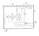
- the inductively operating voltage transformer device is embedded in an insulating body 1 and comprises a primary winding 2 and a secondary winding 4 electrically arranged near the winding 1 and power supplying an electronic card or circuit 5, receiving a measurement signal from a current sensor 3 series coupled to a line wire 6 power supplying the train, said wire 6, therethrough the train drained/supplied current passes, is integrally coupled to the winding 2, thereby the voltage between the wire 6 and ground 10 will be applied to the train, said electronic card or circuit 5 sending information from said sensor 3 through an optical fiber 7 to a second electronic card or circuit 12 receiving the signal from the optical fiber 7 and transforming it into an electric signal to be read by an energy meter, together with the signal taken from the winding 9 and suitably conditioned by the electronic card 12, a secondary winding 8 available on a connector 11 or another dedicated connector to provide the traction driver operating voltage being moreover provided.
- the insulating body 1 of the measurement device for measuring voltage and current on board of railroad vehicles is an insulator assembly including the transformer windings whereas the current sensor 3 may be installed on the top portion of the insulating body 2 together with the electronic card 5 and related connections, as shown in the accompanying drawing.
- the inventive measurement device operates based on an inductively operating transformer 13, including transformer windings 8 and 9, the first of which is used for measuring voltage of the train drivers, the second power supplying an electronic circuit 12 arranged on a bottom portion of the insulating body 1, sending measurements to the power meter.
- the transformer 13 winding 4 is weakly insulated from the primary winding 2, and power supplies the electronic card or circuit 5 for measuring current 3 and transmitting the signal through the optical fiber 7 to the bottom portion of the insulating body 1.
- said transformer 13 winding 4 is arranged near the high voltage portion of the primary winding 2, the latter being connected, at an end thereof, to the high voltage wire 6 and, at the other end thereof, to the vehicle ground or earth 10.
- said transformer 13 operates both at 50 and 16.66 Hz, while assuring the same minimum performance both with respect to the power and the measurement precision.
- the electronic circuit 5, power supplied by the winding 4, receives a signal proportional to the current drained/supplied by the current sensor 3 and performs a digital conversion of the signal, by a known method, while transmitting the converted signal, through the optical fiber 7 to the electronic circuit 12.
- the latter may process the received current signal, to be eventually transformed into an electric analogic signal and, if required, transmit in an electric form the digital signal.
- the electric circuit 12 receives, moreover, the electric line voltage signal, from the winding 9 of the transformer 13 and it may send said signal, if required, directly to the power meter, on board of the train, through the connector 11 or process it, if required, to transform by known methods said signal into a digital signal.
- circuit 12 may also process both the received voltage and current signals to calculate therefrom target parameters, such as power and energy measurement parameters.
- the measurements performed by the electronic circuit 5 and processed by the electronic circuit 12 may be, if required, redundant measurements or two identical circuits, of a type 5 or of a type 12, may be used, for performing the same functions and using two optical fibers 7 to increase the device operating reliability.
Landscapes
- Engineering & Computer Science (AREA)
- Physics & Mathematics (AREA)
- General Physics & Mathematics (AREA)
- Life Sciences & Earth Sciences (AREA)
- Sustainable Development (AREA)
- Sustainable Energy (AREA)
- Power Engineering (AREA)
- Transportation (AREA)
- Mechanical Engineering (AREA)
- Electric Propulsion And Braking For Vehicles (AREA)
- Force Measurement Appropriate To Specific Purposes (AREA)
Applications Claiming Priority (1)
| Application Number | Priority Date | Filing Date | Title |
|---|---|---|---|
| ITMI2010A000598A IT1399218B1 (it) | 2010-04-09 | 2010-04-09 | Dispositivo per la misura di tensione e corrente a bordo di veicoli ferroviari a trazione elettrica |
Publications (1)
| Publication Number | Publication Date |
|---|---|
| EP2374650A1 true EP2374650A1 (fr) | 2011-10-12 |
Family
ID=43218152
Family Applications (1)
| Application Number | Title | Priority Date | Filing Date |
|---|---|---|---|
| EP11002562A Withdrawn EP2374650A1 (fr) | 2010-04-09 | 2011-03-29 | Dispositif de mesure de courant électrique et de tension au board de véhicules ferroviaires à traction électrique |
Country Status (2)
| Country | Link |
|---|---|
| EP (1) | EP2374650A1 (fr) |
| IT (1) | IT1399218B1 (fr) |
Cited By (2)
| Publication number | Priority date | Publication date | Assignee | Title |
|---|---|---|---|---|
| CN103715909A (zh) * | 2013-01-16 | 2014-04-09 | 株洲中车轨道交通装备有限公司 | 一种电力机车用电子式电压互感器及其使用方法 |
| CN112198383A (zh) * | 2020-09-25 | 2021-01-08 | 中铁西安勘察设计研究院有限责任公司 | 铁路柱上计量系统 |
Citations (4)
| Publication number | Priority date | Publication date | Assignee | Title |
|---|---|---|---|---|
| US5530328A (en) * | 1993-12-23 | 1996-06-25 | Pulse Electronics, Inc. | Consist power monitor |
| WO2007104464A2 (fr) * | 2006-03-13 | 2007-09-20 | Knorr-Bremse Systeme für Schienenfahrzeuge GmbH | Dispositif de réception et de transmission d'énergie électrique pour véhicules sur rails |
| EP1844970A2 (fr) * | 2006-04-12 | 2007-10-17 | Knorr-Bremse Systeme für Schienenfahrzeuge GmbH | Système de transport urbain doté d'une mesure de l'énergie à distante |
| EP2224251A1 (fr) * | 2009-02-26 | 2010-09-01 | Tem Elettronica S.r.l. | Dispositif de communication et de mesure de la tension et du courant à bord d'un véhicule ferroviaire à entrainement électrique |
-
2010
- 2010-04-09 IT ITMI2010A000598A patent/IT1399218B1/it active
-
2011
- 2011-03-29 EP EP11002562A patent/EP2374650A1/fr not_active Withdrawn
Patent Citations (4)
| Publication number | Priority date | Publication date | Assignee | Title |
|---|---|---|---|---|
| US5530328A (en) * | 1993-12-23 | 1996-06-25 | Pulse Electronics, Inc. | Consist power monitor |
| WO2007104464A2 (fr) * | 2006-03-13 | 2007-09-20 | Knorr-Bremse Systeme für Schienenfahrzeuge GmbH | Dispositif de réception et de transmission d'énergie électrique pour véhicules sur rails |
| EP1844970A2 (fr) * | 2006-04-12 | 2007-10-17 | Knorr-Bremse Systeme für Schienenfahrzeuge GmbH | Système de transport urbain doté d'une mesure de l'énergie à distante |
| EP2224251A1 (fr) * | 2009-02-26 | 2010-09-01 | Tem Elettronica S.r.l. | Dispositif de communication et de mesure de la tension et du courant à bord d'un véhicule ferroviaire à entrainement électrique |
Non-Patent Citations (1)
| Title |
|---|
| TREIGE P ET AL: "Energiemessung auf elektischen Triebfahrzeugen bei der Deutschen Bahn./On-board energy measurment at electric motor vehicles of Deutsche Bahn./", ELEKTRISCHE BAHNEN, OLDENBOURG INDUSTRIEVERLAG, MUNCHEN, DE, vol. 98, no. 8, 1 August 2000 (2000-08-01), pages 300 - 305, XP008083735, ISSN: 0013-5437 * |
Cited By (3)
| Publication number | Priority date | Publication date | Assignee | Title |
|---|---|---|---|---|
| CN103715909A (zh) * | 2013-01-16 | 2014-04-09 | 株洲中车轨道交通装备有限公司 | 一种电力机车用电子式电压互感器及其使用方法 |
| CN103715909B (zh) * | 2013-01-16 | 2016-06-22 | 株洲中车轨道交通装备有限公司 | 一种电力机车用电子式电压互感器及其使用方法 |
| CN112198383A (zh) * | 2020-09-25 | 2021-01-08 | 中铁西安勘察设计研究院有限责任公司 | 铁路柱上计量系统 |
Also Published As
| Publication number | Publication date |
|---|---|
| ITMI20100598A1 (it) | 2011-10-10 |
| IT1399218B1 (it) | 2013-04-11 |
Similar Documents
| Publication | Publication Date | Title |
|---|---|---|
| US8432175B2 (en) | System and method for evaluating vehicle charging circuits | |
| EP2635910B1 (fr) | Capteur de décharge partielle pour un dispositif de surveillance d'isolation haute tension | |
| CN111372809B (zh) | 用于检测由充电站传输的电能的测量设备和方法 | |
| CN103293372B (zh) | 电量传感器、电量传感器的增设单元以及电量计测系统 | |
| US20110298475A1 (en) | Method and device for monitoring a sheath voltage arrester of a cable system | |
| JP5443094B2 (ja) | 電気自動車用急速充電器の充電ケーブル絶縁試験装置 | |
| CN101837736A (zh) | 一种电力机车供电系统漏电流检测方式及装置 | |
| CN106841815A (zh) | 一种基于电压激励的电力线铁塔接地电阻在线测试仪 | |
| KR101333584B1 (ko) | 고전압 위상 동기화 기능을 갖는 전력 케이블용 부분방전 측정 장치 및 방법 | |
| EP2374650A1 (fr) | Dispositif de mesure de courant électrique et de tension au board de véhicules ferroviaires à traction électrique | |
| EP0936469A3 (fr) | Appareil de test de la résistance de boucle pour la surveillance de l'intégrité d'un blindage de câble | |
| KR100821702B1 (ko) | 전차선로의 임피던스 측정장치 및 이를 이용한 고장점표정방법 | |
| KR100922632B1 (ko) | 송배전선로용 이상판별장치 | |
| CN206906496U (zh) | 一种用于变压器的变比测试仪 | |
| US20150244163A1 (en) | Current and voltage module and methods of monitoring current and voltage in power distribution systems | |
| KR102174151B1 (ko) | 변류기 및 변성기 오차율 검사 장치 | |
| CN102096018A (zh) | 检查大型发电机定子绕组接头焊接质量的方法 | |
| CN114362097B (zh) | 高压漏电保护电路及漏电分析芯片 | |
| CN206990679U (zh) | 一种基于电压激励的电力线铁塔接地电阻在线测试仪 | |
| CN113109646B (zh) | 一种基于语音的电力电缆识别方法和电缆识别仪 | |
| JPH08220162A (ja) | 誘電体損失角測定装置 | |
| KR101527942B1 (ko) | 전철변전소 제어케이블의 접지점 거리측정장치 및 방법 | |
| CN208421171U (zh) | 一种高压断路器机械故障试验工具 | |
| JP2623885B2 (ja) | 樹脂モールド変圧器の部分放電検出装置 | |
| KR100517106B1 (ko) | 가선전압 및 가선전류에 의한 전기철도차량의 전기 제동력측정장치 및 그 방법 |
Legal Events
| Date | Code | Title | Description |
|---|---|---|---|
| PUAI | Public reference made under article 153(3) epc to a published international application that has entered the european phase |
Free format text: ORIGINAL CODE: 0009012 |
|
| AK | Designated contracting states |
Kind code of ref document: A1 Designated state(s): AL AT BE BG CH CY CZ DE DK EE ES FI FR GB GR HR HU IE IS IT LI LT LU LV MC MK MT NL NO PL PT RO RS SE SI SK SM TR |
|
| AX | Request for extension of the european patent |
Extension state: BA ME |
|
| 17P | Request for examination filed |
Effective date: 20120314 |
|
| GRAP | Despatch of communication of intention to grant a patent |
Free format text: ORIGINAL CODE: EPIDOSNIGR1 |
|
| RIC1 | Information provided on ipc code assigned before grant |
Ipc: B60L 3/12 20060101ALI20160919BHEP Ipc: G01R 15/14 20060101AFI20160919BHEP |
|
| INTG | Intention to grant announced |
Effective date: 20161007 |
|
| STAA | Information on the status of an ep patent application or granted ep patent |
Free format text: STATUS: THE APPLICATION HAS BEEN WITHDRAWN |
|
| 18W | Application withdrawn |
Effective date: 20170208 |