EP2374747B1 - Système de composants d'un système d'ascenseur aux étages de la cage d'ascenseur et procédé de montage correspondant - Google Patents
Système de composants d'un système d'ascenseur aux étages de la cage d'ascenseur et procédé de montage correspondant Download PDFInfo
- Publication number
- EP2374747B1 EP2374747B1 EP20100425116 EP10425116A EP2374747B1 EP 2374747 B1 EP2374747 B1 EP 2374747B1 EP 20100425116 EP20100425116 EP 20100425116 EP 10425116 A EP10425116 A EP 10425116A EP 2374747 B1 EP2374747 B1 EP 2374747B1
- Authority
- EP
- European Patent Office
- Prior art keywords
- runway
- elevator
- crosspiece
- lower jig
- jig
- Prior art date
- Legal status (The legal status is an assumption and is not a legal conclusion. Google has not performed a legal analysis and makes no representation as to the accuracy of the status listed.)
- Active
Links
Images



Classifications
-
- B—PERFORMING OPERATIONS; TRANSPORTING
- B66—HOISTING; LIFTING; HAULING
- B66B—ELEVATORS; ESCALATORS OR MOVING WALKWAYS
- B66B13/00—Doors, gates, or other apparatus controlling access to, or exit from, cages or lift well landings
- B66B13/30—Constructional features of doors or gates
-
- B—PERFORMING OPERATIONS; TRANSPORTING
- B66—HOISTING; LIFTING; HAULING
- B66B—ELEVATORS; ESCALATORS OR MOVING WALKWAYS
- B66B13/00—Doors, gates, or other apparatus controlling access to, or exit from, cages or lift well landings
- B66B13/30—Constructional features of doors or gates
- B66B13/301—Details of door sills
-
- B—PERFORMING OPERATIONS; TRANSPORTING
- B66—HOISTING; LIFTING; HAULING
- B66B—ELEVATORS; ESCALATORS OR MOVING WALKWAYS
- B66B13/00—Doors, gates, or other apparatus controlling access to, or exit from, cages or lift well landings
- B66B13/30—Constructional features of doors or gates
- B66B13/306—Details of door jambs
-
- B—PERFORMING OPERATIONS; TRANSPORTING
- B66—HOISTING; LIFTING; HAULING
- B66B—ELEVATORS; ESCALATORS OR MOVING WALKWAYS
- B66B19/00—Mining-hoist operation
-
- B—PERFORMING OPERATIONS; TRANSPORTING
- B66—HOISTING; LIFTING; HAULING
- B66B—ELEVATORS; ESCALATORS OR MOVING WALKWAYS
- B66B5/00—Applications of checking, fault-correcting, or safety devices in elevators
Definitions
- the present invention relates to a system of component parts of an elevator system at the floors of the runway, and relative mounting method, adapted to allow the mounting of doors at the floors, and interchangeable modular infill of the runway of said elevator system.
- Elevator systems are installed inside an elevator runway that is generally constructed at the same time as the structural elements of buildings.
- Said elevator runway is therefore made of reinforced concrete to define a parallelepiped that runs for at least the entire height of the building and which has an opening for each landing served by the elevator system.
- the doors of the various floors must be equidistant and perfectly aligned with one another, so that the motors of the car can, by means of suitable couplings, open the doors correctly on each landing.
- the openings of the elevator runway must be blocked off in order to prevent people from accidentally falling into the elevator runway.
- carpenters provide a barrier, generally made of wood, nailed to the walls defining the stairwell, until it is time for the team of workers to mount the doors at the floors.
- a principal problem is that of reducing to a minimum any adjustments to the finishes after mounting of the doors at the floors, and another no less important problem concerning safety is that of ensuring that the openings of the elevator runway are blocked off on each landing.
- EP 1 679 281 A1 discloses a system according to the preamble of apparatus claim 1.
- the object of the present invention is to provide a system of component parts of an elevator system at the floors of the runway, and relative mounting method, adapted to solve said mounting and safety problems, and to allow mounting of doors at the floors, and modular infill of the runway of the elevator system.
- a particular object of the present invention is a system of component parts of an elevator system at the floors of the runway, and relative mounting method, as better described in the claims, which form an integral part of the present description.
- the system forming the subject of the present invention provides for the mounting of an upper crosspiece 1 and a lower jig 2.
- Said crosspiece and said jig define the exact position of the suspensions and of the thresholds of the doors of all the floors.
- preliminary positioning of a jig 2 and of an upper crosspiece 1 for each opening of the elevator runway allows constructional inaccuracies of the structures to be corrected, as workers called to lay flooring and apply plaster are obliged to take said jigs and crosspieces as reference for finishing each landing.
- it is no longer necessary to carry out any structural preparation for positioning of the doors at each opening of the elevator runway as positioning of the upper crosspiece 1 and of the jig 2 allows filling panels, defining the edge margins of the opening of the doors, to be installed.
- said upper crosspiece 1 is of a length equivalent to the width of the side of the elevator runway in which the opening is produced and is anchored to the runway at the ends, abutting against the side walls, to define a fixed-end beam.
- This anchoring ensures that the position of the crosspiece can be adjusted to ensure it is plumb in relation to the respective jig 2 and consequently to all the other jigs of all the other openings of the runway at other floors.
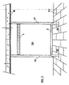
- the lower jig 2 is also of the same length as the width of the side of the elevator runway in which the opening is produced, minus the dimensions of the finishes 37 and a further adjustment margin 38 ( Fig. 3 ).
- said lower jig has an S-shaped section in which an upper plate 2' and a lower plate 2" are parallel and staggered and joined by a transverse plate 2'" to the first two ( Fig. 2 ).
- Said jig 2 is mounted so that said upper plate 2' defines the level of the floor PV for the subsequent flooring step.
- Said lower plate 2'' being staggered with respect to the upper plate 2', projects into the elevator runway for application of the threshold for sliding of the doors at the landing, which slide inside the elevator runway.
- said upper crosspiece 1 is produced by means of a box element, for example with a C-section with internal (or also external) folded edges, although other shapes can be used.
- one or more fall prevention rails 3 can be positioned between said upper crosspiece 1 and said lower plate 2" of said lower jig 2 to define a fall prevention barrier ( Fig. 4 ).
- said lower plate 2" and said upper crosspiece 1 comprise a suitable number of holes through which to anchor, for example with screws, or by interlocking, said fall prevention rails 3.
- connection of said fall prevention rails 3 to said jig and to said crosspiece is such as to maintain the rails inside the elevator runway, avoiding any interference with the application of plaster, marble, wood or tiles.
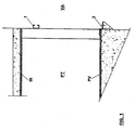
- Fig. 1 shows a section of an elevator runway VA at a landing PT. It can be clearly seen that the floor PV has been laid so as to pass under the upper plate 2' of the jig 2.
- the floor can be taken perfectly to the level of said first plate 2' or can be at a slightly higher level to said plate.
- said upper plate 2' is provided with an anti-slip covering (not shown).
- the plastering of the ceiling and of the walls can be applied with continuity up to the inner edge of the openings of the elevator runway VA, taking as reference the transverse plate 2'" of the jig and the edge of the upper crosspiece 1 outside the runway.
- the jig 2 is associated with the floor of a landing PT, for example by means of two or more first square support elements 4.
- first square support elements 4 in addition to or alternatively to said first square elements 4, second square elements can be provided, adapted to be associated with the lateral walls to support said jig 2 in proximity of the respective ends.
- Said square support elements comprise slots extending sufficiently to allow adjustable mounting of said lower jig 2 with respect to the runway VA, both vertically and horizontally.
- Fig. 4 shows installation of said rails 3 associated with said crosspiece and with said jig.
- Said rails 3, in a preferred variant comprise one or more hooked elements 31, for insertion of planks or other suitable horizontal fall prevention elements 32 contributing towards blocking off access to the elevator runway.
- Said rails 3 can comprise different anchoring means of horizontal fall prevention elements.
- said elevator runway VA is preferably completely open, in the sense that at each landing its opening is defined at the perimeter by the floor, by the ceiling and by the lateral walls of the runway itself.
- the elevator runway can be formed of only three sides, without counting the surface of the soffit depth which at each landing faces the elevator runway.
- Fig. 5 shows an exploded view of the component parts for installation of the system at a landing, in a situation in which the opening of the elevator runway is complete. Horizontal 10 and vertical 11, 12 infill panels are also shown.
- the upper crosspiece 1 and the lower jig 2 are advantageously of a length such as to almost entirely cover the width of the elevator runway.
- the infill panels (10, 11, 12), installed subsequently, are composed of sheets comprising bends at the edges and structural support elements, inserted in the edge bends, in the inner part of the sheets facing the elevator runway.
- the edge bends are preferably only present on two opposite sides of the panel: for example, in the vertical panels 11 and 12 bends 20, 21 are present on the vertical sides, while in the horizontal panel bends 22, 23 are present on the horizontal sides.
- vertical and horizontal refer to the direction when mounted.
- an upper support bar 30 is inserted horizontally between the bends 20, 21 of the vertical sheet 11, and anchored there in a slightly higher position to that corresponding to the crosspiece 1, with rivets.
- At least one square 31 in the shape of an S facing the inside of the panel is anchored to the upper bar 30. When mounting the panel, the square is used to hang the panel to the upper crosspiece.
- a lower bar 32 is inserted horizontally between the bends 20, 21 of the vertical sheet 11 on the bottom thereof. After having hung the panel to the crosspiece, the upper bar is anchored to the crosspiece 1, while the lower bar is anchored to the jig 2, for example with screws.
- Further reinforcing elements are formed by a further horizontal bar 33 and a box rail 15 anchored between the two bars 32 and 33 and anchored to the inner side of the panel 11, for example by gluing.
- the further reinforcing elements can be omitted depending on the width of the panel, for example in the narrower vertical panel 12, which is however installed in the same manner as the panel 11, on the opposite side of the runway. Therefore, the panel 12 comprises, similarly to the panel 11, an upper bar 30' and a lower bar 32', and a square 31'.
- Two box elements 34, 35 are inserted vertically at opposite sides of the horizontal panel 10, in the bends 22, 23.
- Squares 36, 36' are anchored to the box elements.
- the horizontal panel 10 is installed in the same manner as the vertical ones, first hung on the crosspiece 1 through the squares, then anchored to the crosspiece and to the vertical panels.
- L-shaped beading strips 17 are inserted at the vertical edges.
- the horizontal crosspiece 16 is anchored with rivets to the upper end of the panels 10, 11, and 12, and contributes towards the alignment thereof.
- a vertical stop 40, to stop the doors in closed position, and a horizontal element 41 can also be present laterally.
- the infill is composed of panels with anchoring system to the structural part that allows them to be substituted in time with a simple and rapid operation without work on the structural part, on the suspensions and on the landing door panels which remain installed also during this operation.
- infill panels also simplifies positioning of the elevator call button, as it can be produced directly on the infill panel. See, for example, Fig. 6 in which the call buttons 28 are installed directly on the panel 11.
- the mounting method of the invention makes it possible, for the entire time rqeuired for this mounting, to avoid masonry works, as work takes place with the runways fully open at the floors.
- the system of the invention also allows installation of door openings on different sides at the various floors, in the case in which it is necessary to provide the elevator car with doors on more than one side, for door opening on different sides at different floors of the building.
Landscapes
- Elevator Door Apparatuses (AREA)
- Lift-Guide Devices, And Elevator Ropes And Cables (AREA)
Claims (15)
- Système de pièces composantes d'un système d'ascenseur au niveau des étages de la cage (VA) du système, comportant :un gabarit de montage inférieur (2),une pièce transversale supérieure (1) comportant des moyens d'ancrage (6) pouvant être réglés pour fixer ladite pièce transversale (1) en butée contre les parois latérales de la cage de façon à être en aplomb par rapport au dit gabarit de montage (2),caractérisé en ce que ledit gabarit de montage inférieur (2) comporte une section configurée en forme de S dans laquelle une plaque supérieure (2') et une plaque inférieure (2") sont parallèles et en décalage et reliées par une plaque transversale (2"'), ledit gabarit de montage (inférieur 2) est adapté pour être monté afin de définir sur un premier côté, avec ladite plaque supérieure (2') un niveau d'un étage et sur un second côté opposé, avec ladite plaque inférieure (2") afin de définir un guide de coulissement des portes du système d'ascenseur dans la cage (VA).
- Système selon la revendication 1, comprenant, de plus, un ou plusieurs rails de prévention de chute (3) et dans lequel ledit gabarit de montage inférieur (2) et ladite pièce transversale supérieure (1) comportent des moyens d'ancrage afin de maintenir ledit rail ou lesdits rails de prévention de chute (3) verticalement entre ledit gabarit de montage inférieur (2) et ladite pièce transversale supérieure (1).
- Système selon la revendication 1, dans lequel la plaque supérieure (2') est adaptée pour être montée à plat sur le plancher, ladite plaque inférieure (2") étant décalée par rapport à la plaque supérieure (2'), s'avançant dans la cage de l'ascenseur en vue d'une application du seuil pour faire coulisser les portes au niveau de l'arrivée à l'étage, en vue de coulisser à l'intérieur de la cage d'ascenseur.
- Système selon la revendication 1, dans lequel ladite pièce transversale supérieure (1) est configurée en forme de C avec des bords repliés, et/ou dans lequel lesdits moyens d'ancrage (6) sont configurés en forme de L adaptés pour être couplés avec une paroi périphérique de la cage et à une surface définissant ladite pièce transversale supérieure, perpendiculaire par rapport à ladite paroi périphérique.
- Système selon la revendication 2, dans lequel ledit rail ou lesdits rails de prévention comporte(nt) au moins un élément à crochet (31) pour l'ancrage d'un ou de plusieurs élément(s) horizontal (horizontaux) de prévention de chute (32).
- Système selon l'une quelconque des revendications précédentes comprenant, de plus, un élément de remplissage comprenant un ou plusieurs panneau(x) modulaire(s) (10, 11, 12) raccordé(s) au dit gabarit de montage inférieur (2) et/ou à ladite pièce transversale supérieure (1) pour finir et couvrir la cage au niveau des étages, en excluant la surface des encadrements de porte.
- Système selon la revendication 6, dans lequel lesdits panneaux (10, 11, 12) comportent des coudes au niveau des bords et des éléments de support de la structure (30, 32, 33, 30', 32') et/ou des éléments configurés en forme de caisson (34, 35) insérés dans lesdits coudes.
- Système selon la revendication 7, dans lequel une ou plusieurs équerre(s) (31, 31', 36, 36') conçue(s) pour permettre aux dits panneaux modulaires d'être suspendus sur ladite pièce transversale pendant le montage, sont fixés à, au moins un, élément de support de la structure et/ou à un élément configuré en forme de caisson.
- Système selon la revendication 8, dans lequel lesdits panneaux (10, 11, 12) comportent un ou plusieurs rail(s) configuré(s) en forme de caisson (15) conçu(s) pour être fixé(s) entre lesdits éléments de support de la structure.
- Système selon la revendication 6, comprenant des bandes de bourrelet de couverture (16, 17, 18) sur le bord dudit élément de remplissage.
- Système selon la revendication 3 comprenant, de plus, un premier (4) et/ou un second élément(s) d'équerre(5) pour supporter ledit gabarit de montage inférieur (2) comportant des fentes appropriées de façon à permettre une fixation réglable dudit gabarit de montage inférieur (2).
- Procédé de montage d'un système selon l'une quelconque des revendications précédentes, dans au moins une cage (VA) d'un système d'ascenseur comportant les étapes suivantes comprenant le fait de :- appliquer ledit gabarit de montage inférieur (2) sur ladite cage (VA) avant d'établir le sol d'un palier respectif (PT) de sorte que ladite plaque supérieure (2') définit un niveau du sol dudit palier (PT) et que ladite plaque inférieure (2") définit un guide de coulissement des portes de l'ascenseur dans la cage (VA), ladite plaque inférieure faisant face à la cage (VA) ;- monter ladite pièce transversale supérieure de façon qu'elle soit d'aplomb par rapport au dit gabarit de montage inférieur (2).
- Procédé selon la revendication 12, dans lequel l'application dudit gabarit de montage inférieur est réalisée de façon perpendiculaire et parallèle par rapport à un autre gabarit de montage inférieur (2) d'une autre ouverture de la cage (VA).
- Procédé selon la revendication 12 comprenant une étape consistant à accrocher un ou plusieurs rail(s) de prévention de chute (3) au niveau du haut à ladite pièce transversale supérieure (1) et au niveau du bas au dit gabarit de montage inférieur (2), cela étant possible pour appliquer ultérieurement des éléments de prévention de chute supplémentaires (32) au dit rail ou aux dits plusieurs rails de prévention de chute.
- Procédé selon la revendication 12 comportant, de plus, les étapes comprenant de :- monter lesdits panneaux d'éléments de remplissage (10, 11, 12) en les accrochant à ladite pièce transversale (1) et en fixant ensuite à la pièce transversale et au dit gabarit de montage (2) ;- fixer lesdites bandes de bourrelet de couverture (16, 17, 18) au bord dudit élément de remplissage.
Priority Applications (2)
| Application Number | Priority Date | Filing Date | Title |
|---|---|---|---|
| EP20100425116 EP2374747B1 (fr) | 2010-04-12 | 2010-04-12 | Système de composants d'un système d'ascenseur aux étages de la cage d'ascenseur et procédé de montage correspondant |
| SM201400018T SMT201400018B (it) | 2010-04-12 | 2014-02-12 | Sistema di parti componenti di un impianto elevatore ai piani del vano di corsa e relativo metodo dimontaggio |
Applications Claiming Priority (1)
| Application Number | Priority Date | Filing Date | Title |
|---|---|---|---|
| EP20100425116 EP2374747B1 (fr) | 2010-04-12 | 2010-04-12 | Système de composants d'un système d'ascenseur aux étages de la cage d'ascenseur et procédé de montage correspondant |
Publications (2)
| Publication Number | Publication Date |
|---|---|
| EP2374747A1 EP2374747A1 (fr) | 2011-10-12 |
| EP2374747B1 true EP2374747B1 (fr) | 2013-11-13 |
Family
ID=42668712
Family Applications (1)
| Application Number | Title | Priority Date | Filing Date |
|---|---|---|---|
| EP20100425116 Active EP2374747B1 (fr) | 2010-04-12 | 2010-04-12 | Système de composants d'un système d'ascenseur aux étages de la cage d'ascenseur et procédé de montage correspondant |
Country Status (2)
| Country | Link |
|---|---|
| EP (1) | EP2374747B1 (fr) |
| SM (1) | SMT201400018B (fr) |
Families Citing this family (2)
| Publication number | Priority date | Publication date | Assignee | Title |
|---|---|---|---|---|
| EP3678973A1 (fr) * | 2017-09-07 | 2020-07-15 | KONE Corporation | Ensemble porte palière d'ascenseur et procédé d'installation de la porte palière |
| WO2019166685A1 (fr) * | 2018-02-28 | 2019-09-06 | Kone Corporation | Ensemble porte palière d'ascenseur et son procédé de montage |
Family Cites Families (14)
| Publication number | Priority date | Publication date | Assignee | Title |
|---|---|---|---|---|
| US3426480A (en) * | 1967-07-07 | 1969-02-11 | Westinghouse Electric Corp | Door assembly |
| FR2120596A5 (fr) * | 1971-01-07 | 1972-08-18 | Labrosse Joseph | |
| US3741351A (en) * | 1971-03-05 | 1973-06-26 | Westinghouse Electric Corp | Integrated elevator construction |
| US4875552A (en) * | 1986-07-29 | 1989-10-24 | Montgomery Elevator Company | Modular elevator cab construction |
| DK0512210T3 (da) * | 1991-05-02 | 1996-02-26 | Inventio Ag | Beskyttelsesindretning for dørmontering ved elevatorer |
| DE9409561U1 (de) * | 1994-06-14 | 1994-08-04 | Thyssen Aufzüge GmbH, 73765 Neuhausen | Führungsanordnung für Schiebetüren, insbesondere Aufzugstüren |
| US6145630A (en) * | 1996-01-25 | 2000-11-14 | Friedman; Harold S. | Sliding elevator-door assembly and method of installation |
| FI103030B (fi) * | 1998-05-05 | 1999-04-15 | Kone Corp | Ovikehysjärjestelmä hissin kerrostaso-ovea varten |
| JP2002348078A (ja) * | 2001-05-14 | 2002-12-04 | Inventio Ag | リフトシャフトドアのドアフレーム |
| DE10333086A1 (de) * | 2003-07-21 | 2005-02-17 | Wittur Ag | Abweisende Türpaneelführung |
| US7322555B2 (en) * | 2005-01-10 | 2008-01-29 | The Peelle Company Ltd. | Track jack system |
| ITBG20060012U1 (it) * | 2006-04-21 | 2007-10-22 | Sematic Italia Spa | Pannello perfezionato per porte di ascensori |
| KR100742315B1 (ko) * | 2007-01-25 | 2007-07-24 | (주)두성엔티 | 엘리베이터 도어의 이탈 방지 장치 |
| EP2019074A1 (fr) * | 2007-07-26 | 2009-01-28 | Macpuar, S.A. | Porte automatique d'ascenseur et son procédé d'assemblage |
-
2010
- 2010-04-12 EP EP20100425116 patent/EP2374747B1/fr active Active
-
2014
- 2014-02-12 SM SM201400018T patent/SMT201400018B/xx unknown
Also Published As
| Publication number | Publication date |
|---|---|
| SMT201400018B (it) | 2014-05-07 |
| EP2374747A1 (fr) | 2011-10-12 |
Similar Documents
| Publication | Publication Date | Title |
|---|---|---|
| RU2194004C2 (ru) | Способ и устройство для монтажа лифта | |
| CN104981575B (zh) | 幕墙板安装系统 | |
| KR20190114731A (ko) | 건축물의 슬라브 시공 장치 및 방법 | |
| AU2017202444B2 (en) | A void platform and a method for providing a platform support across a building void | |
| US11498812B2 (en) | Elevator landing door assembly and its installation method | |
| US6145630A (en) | Sliding elevator-door assembly and method of installation | |
| EP2217784B1 (fr) | Appareil et procédé pour installer des fenêtres dans une construction à ossature de bois | |
| US5479754A (en) | Method and apparatus for installing an elevator shaft door | |
| US6202798B1 (en) | Elevator entrance door assembly and method of installation | |
| EP2374747A1 (fr) | Système de pièces de composants d'un système ascenseur au sol d'une gaine d'ascenseur et procédé de montage correspondant | |
| EP2774887B1 (fr) | Unité de seuil de porte et procédé pour une unité de porte de palier d'ascenseur | |
| US11554935B2 (en) | Elevator car | |
| KR100731315B1 (ko) | 갱폼 가이드부재 및 이를 이용한 이동용 거푸집 시스템 | |
| GB2580760A (en) | A hatch | |
| KR100901016B1 (ko) | 건축물의 외벽 비계 안전 브라켓 | |
| AU2002301166B2 (en) | Method and insertion frame for installing a shaft door of a lift installation | |
| EP2031142A1 (fr) | Système de cloison modulaire | |
| JP2018141358A (ja) | 出入口用建具 | |
| JP6412712B2 (ja) | 出入口用建具 | |
| CA3001228C (fr) | Une plateforme de vide et une methode de fourniture d'un support de plateforme traversant un vide de batiment | |
| JP6317166B2 (ja) | 出入口用建具 | |
| BR102012012420A2 (pt) | caixa de corrida metÁlica de elevador com dupla funÇço como elevador de obra e elevador de passageiros | |
| HK40033079B (en) | Elevator landing door assembly and its installation method | |
| NZ731013B (en) | A void platform and a method for providing a platform support across a building void | |
| HK40033079A (en) | Elevator landing door assembly and its installation method |
Legal Events
| Date | Code | Title | Description |
|---|---|---|---|
| PUAI | Public reference made under article 153(3) epc to a published international application that has entered the european phase |
Free format text: ORIGINAL CODE: 0009012 |
|
| AK | Designated contracting states |
Kind code of ref document: A1 Designated state(s): AT BE BG CH CY CZ DE DK EE ES FI FR GB GR HR HU IE IS IT LI LT LU LV MC MK MT NL NO PL PT RO SE SI SK SM TR |
|
| AX | Request for extension of the european patent |
Extension state: AL BA ME RS |
|
| 17P | Request for examination filed |
Effective date: 20120412 |
|
| 17Q | First examination report despatched |
Effective date: 20120604 |
|
| GRAP | Despatch of communication of intention to grant a patent |
Free format text: ORIGINAL CODE: EPIDOSNIGR1 |
|
| INTG | Intention to grant announced |
Effective date: 20130604 |
|
| GRAS | Grant fee paid |
Free format text: ORIGINAL CODE: EPIDOSNIGR3 |
|
| GRAA | (expected) grant |
Free format text: ORIGINAL CODE: 0009210 |
|
| AK | Designated contracting states |
Kind code of ref document: B1 Designated state(s): AT BE BG CH CY CZ DE DK EE ES FI FR GB GR HR HU IE IS IT LI LT LU LV MC MK MT NL NO PL PT RO SE SI SK SM TR |
|
| REG | Reference to a national code |
Ref country code: GB Ref legal event code: FG4D |
|
| REG | Reference to a national code |
Ref country code: CH Ref legal event code: EP |
|
| REG | Reference to a national code |
Ref country code: AT Ref legal event code: REF Ref document number: 640494 Country of ref document: AT Kind code of ref document: T Effective date: 20131215 |
|
| REG | Reference to a national code |
Ref country code: IE Ref legal event code: FG4D |
|
| REG | Reference to a national code |
Ref country code: DE Ref legal event code: R096 Ref document number: 602010011699 Country of ref document: DE Effective date: 20140109 |
|
| REG | Reference to a national code |
Ref country code: CH Ref legal event code: NV Representative=s name: KATZAROV S.A., CH |
|
| REG | Reference to a national code |
Ref country code: NL Ref legal event code: VDEP Effective date: 20131113 |
|
| REG | Reference to a national code |
Ref country code: AT Ref legal event code: MK05 Ref document number: 640494 Country of ref document: AT Kind code of ref document: T Effective date: 20131113 |
|
| REG | Reference to a national code |
Ref country code: LT Ref legal event code: MG4D |
|
| PG25 | Lapsed in a contracting state [announced via postgrant information from national office to epo] |
Ref country code: NO Free format text: LAPSE BECAUSE OF FAILURE TO SUBMIT A TRANSLATION OF THE DESCRIPTION OR TO PAY THE FEE WITHIN THE PRESCRIBED TIME-LIMIT Effective date: 20140213 Ref country code: SE Free format text: LAPSE BECAUSE OF FAILURE TO SUBMIT A TRANSLATION OF THE DESCRIPTION OR TO PAY THE FEE WITHIN THE PRESCRIBED TIME-LIMIT Effective date: 20131113 Ref country code: LT Free format text: LAPSE BECAUSE OF FAILURE TO SUBMIT A TRANSLATION OF THE DESCRIPTION OR TO PAY THE FEE WITHIN THE PRESCRIBED TIME-LIMIT Effective date: 20131113 Ref country code: HR Free format text: LAPSE BECAUSE OF FAILURE TO SUBMIT A TRANSLATION OF THE DESCRIPTION OR TO PAY THE FEE WITHIN THE PRESCRIBED TIME-LIMIT Effective date: 20131113 Ref country code: NL Free format text: LAPSE BECAUSE OF FAILURE TO SUBMIT A TRANSLATION OF THE DESCRIPTION OR TO PAY THE FEE WITHIN THE PRESCRIBED TIME-LIMIT Effective date: 20131113 Ref country code: IS Free format text: LAPSE BECAUSE OF FAILURE TO SUBMIT A TRANSLATION OF THE DESCRIPTION OR TO PAY THE FEE WITHIN THE PRESCRIBED TIME-LIMIT Effective date: 20140313 Ref country code: FI Free format text: LAPSE BECAUSE OF FAILURE TO SUBMIT A TRANSLATION OF THE DESCRIPTION OR TO PAY THE FEE WITHIN THE PRESCRIBED TIME-LIMIT Effective date: 20131113 |
|
| PG25 | Lapsed in a contracting state [announced via postgrant information from national office to epo] |
Ref country code: CY Free format text: LAPSE BECAUSE OF FAILURE TO SUBMIT A TRANSLATION OF THE DESCRIPTION OR TO PAY THE FEE WITHIN THE PRESCRIBED TIME-LIMIT Effective date: 20131113 Ref country code: LV Free format text: LAPSE BECAUSE OF FAILURE TO SUBMIT A TRANSLATION OF THE DESCRIPTION OR TO PAY THE FEE WITHIN THE PRESCRIBED TIME-LIMIT Effective date: 20131113 Ref country code: AT Free format text: LAPSE BECAUSE OF FAILURE TO SUBMIT A TRANSLATION OF THE DESCRIPTION OR TO PAY THE FEE WITHIN THE PRESCRIBED TIME-LIMIT Effective date: 20131113 Ref country code: BE Free format text: LAPSE BECAUSE OF FAILURE TO SUBMIT A TRANSLATION OF THE DESCRIPTION OR TO PAY THE FEE WITHIN THE PRESCRIBED TIME-LIMIT Effective date: 20131113 Ref country code: ES Free format text: LAPSE BECAUSE OF FAILURE TO SUBMIT A TRANSLATION OF THE DESCRIPTION OR TO PAY THE FEE WITHIN THE PRESCRIBED TIME-LIMIT Effective date: 20131113 |
|
| PG25 | Lapsed in a contracting state [announced via postgrant information from national office to epo] |
Ref country code: PT Free format text: LAPSE BECAUSE OF FAILURE TO SUBMIT A TRANSLATION OF THE DESCRIPTION OR TO PAY THE FEE WITHIN THE PRESCRIBED TIME-LIMIT Effective date: 20140313 |
|
| PG25 | Lapsed in a contracting state [announced via postgrant information from national office to epo] |
Ref country code: EE Free format text: LAPSE BECAUSE OF FAILURE TO SUBMIT A TRANSLATION OF THE DESCRIPTION OR TO PAY THE FEE WITHIN THE PRESCRIBED TIME-LIMIT Effective date: 20131113 |
|
| REG | Reference to a national code |
Ref country code: DE Ref legal event code: R097 Ref document number: 602010011699 Country of ref document: DE |
|
| PG25 | Lapsed in a contracting state [announced via postgrant information from national office to epo] |
Ref country code: RO Free format text: LAPSE BECAUSE OF FAILURE TO SUBMIT A TRANSLATION OF THE DESCRIPTION OR TO PAY THE FEE WITHIN THE PRESCRIBED TIME-LIMIT Effective date: 20131113 Ref country code: PL Free format text: LAPSE BECAUSE OF FAILURE TO SUBMIT A TRANSLATION OF THE DESCRIPTION OR TO PAY THE FEE WITHIN THE PRESCRIBED TIME-LIMIT Effective date: 20131113 Ref country code: CZ Free format text: LAPSE BECAUSE OF FAILURE TO SUBMIT A TRANSLATION OF THE DESCRIPTION OR TO PAY THE FEE WITHIN THE PRESCRIBED TIME-LIMIT Effective date: 20131113 Ref country code: SK Free format text: LAPSE BECAUSE OF FAILURE TO SUBMIT A TRANSLATION OF THE DESCRIPTION OR TO PAY THE FEE WITHIN THE PRESCRIBED TIME-LIMIT Effective date: 20131113 |
|
| PLBE | No opposition filed within time limit |
Free format text: ORIGINAL CODE: 0009261 |
|
| STAA | Information on the status of an ep patent application or granted ep patent |
Free format text: STATUS: NO OPPOSITION FILED WITHIN TIME LIMIT |
|
| PG25 | Lapsed in a contracting state [announced via postgrant information from national office to epo] |
Ref country code: DK Free format text: LAPSE BECAUSE OF FAILURE TO SUBMIT A TRANSLATION OF THE DESCRIPTION OR TO PAY THE FEE WITHIN THE PRESCRIBED TIME-LIMIT Effective date: 20131113 |
|
| 26N | No opposition filed |
Effective date: 20140814 |
|
| REG | Reference to a national code |
Ref country code: DE Ref legal event code: R097 Ref document number: 602010011699 Country of ref document: DE Effective date: 20140814 |
|
| PG25 | Lapsed in a contracting state [announced via postgrant information from national office to epo] |
Ref country code: LU Free format text: LAPSE BECAUSE OF FAILURE TO SUBMIT A TRANSLATION OF THE DESCRIPTION OR TO PAY THE FEE WITHIN THE PRESCRIBED TIME-LIMIT Effective date: 20140412 |
|
| REG | Reference to a national code |
Ref country code: IE Ref legal event code: MM4A |
|
| PG25 | Lapsed in a contracting state [announced via postgrant information from national office to epo] |
Ref country code: SI Free format text: LAPSE BECAUSE OF FAILURE TO SUBMIT A TRANSLATION OF THE DESCRIPTION OR TO PAY THE FEE WITHIN THE PRESCRIBED TIME-LIMIT Effective date: 20131113 |
|
| REG | Reference to a national code |
Ref country code: FR Ref legal event code: PLFP Year of fee payment: 6 |
|
| PG25 | Lapsed in a contracting state [announced via postgrant information from national office to epo] |
Ref country code: IE Free format text: LAPSE BECAUSE OF NON-PAYMENT OF DUE FEES Effective date: 20140412 |
|
| PG25 | Lapsed in a contracting state [announced via postgrant information from national office to epo] |
Ref country code: MT Free format text: LAPSE BECAUSE OF FAILURE TO SUBMIT A TRANSLATION OF THE DESCRIPTION OR TO PAY THE FEE WITHIN THE PRESCRIBED TIME-LIMIT Effective date: 20131113 |
|
| REG | Reference to a national code |
Ref country code: FR Ref legal event code: PLFP Year of fee payment: 7 |
|
| PG25 | Lapsed in a contracting state [announced via postgrant information from national office to epo] |
Ref country code: BG Free format text: LAPSE BECAUSE OF FAILURE TO SUBMIT A TRANSLATION OF THE DESCRIPTION OR TO PAY THE FEE WITHIN THE PRESCRIBED TIME-LIMIT Effective date: 20131113 Ref country code: GR Free format text: LAPSE BECAUSE OF FAILURE TO SUBMIT A TRANSLATION OF THE DESCRIPTION OR TO PAY THE FEE WITHIN THE PRESCRIBED TIME-LIMIT Effective date: 20140214 |
|
| PG25 | Lapsed in a contracting state [announced via postgrant information from national office to epo] |
Ref country code: HU Free format text: LAPSE BECAUSE OF FAILURE TO SUBMIT A TRANSLATION OF THE DESCRIPTION OR TO PAY THE FEE WITHIN THE PRESCRIBED TIME-LIMIT; INVALID AB INITIO Effective date: 20100412 Ref country code: TR Free format text: LAPSE BECAUSE OF FAILURE TO SUBMIT A TRANSLATION OF THE DESCRIPTION OR TO PAY THE FEE WITHIN THE PRESCRIBED TIME-LIMIT Effective date: 20131113 |
|
| REG | Reference to a national code |
Ref country code: FR Ref legal event code: PLFP Year of fee payment: 8 |
|
| REG | Reference to a national code |
Ref country code: CH Ref legal event code: PCAR Free format text: NEW ADDRESS: AVENUE DES MORGINES 12, 1213 PETIT-LANCY (CH) |
|
| REG | Reference to a national code |
Ref country code: FR Ref legal event code: PLFP Year of fee payment: 9 |
|
| PG25 | Lapsed in a contracting state [announced via postgrant information from national office to epo] |
Ref country code: MK Free format text: LAPSE BECAUSE OF FAILURE TO SUBMIT A TRANSLATION OF THE DESCRIPTION OR TO PAY THE FEE WITHIN THE PRESCRIBED TIME-LIMIT Effective date: 20131113 |
|
| PGFP | Annual fee paid to national office [announced via postgrant information from national office to epo] |
Ref country code: MC Payment date: 20180522 Year of fee payment: 9 Ref country code: DE Payment date: 20180502 Year of fee payment: 9 |
|
| PGFP | Annual fee paid to national office [announced via postgrant information from national office to epo] |
Ref country code: PL Payment date: 20180423 Year of fee payment: 12 |
|
| PGFP | Annual fee paid to national office [announced via postgrant information from national office to epo] |
Ref country code: GB Payment date: 20180427 Year of fee payment: 9 |
|
| REG | Reference to a national code |
Ref country code: DE Ref legal event code: R119 Ref document number: 602010011699 Country of ref document: DE |
|
| GBPC | Gb: european patent ceased through non-payment of renewal fee |
Effective date: 20190412 |
|
| PG25 | Lapsed in a contracting state [announced via postgrant information from national office to epo] |
Ref country code: MC Free format text: LAPSE BECAUSE OF NON-PAYMENT OF DUE FEES Effective date: 20190430 |
|
| PG25 | Lapsed in a contracting state [announced via postgrant information from national office to epo] |
Ref country code: GB Free format text: LAPSE BECAUSE OF NON-PAYMENT OF DUE FEES Effective date: 20190412 Ref country code: DE Free format text: LAPSE BECAUSE OF NON-PAYMENT OF DUE FEES Effective date: 20191101 |
|
| PG25 | Lapsed in a contracting state [announced via postgrant information from national office to epo] |
Ref country code: SM Free format text: LAPSE BECAUSE OF NON-PAYMENT OF DUE FEES Effective date: 20191107 |
|
| PGFP | Annual fee paid to national office [announced via postgrant information from national office to epo] |
Ref country code: IT Payment date: 20250428 Year of fee payment: 16 |
|
| PGFP | Annual fee paid to national office [announced via postgrant information from national office to epo] |
Ref country code: FR Payment date: 20250426 Year of fee payment: 16 |
|
| PGFP | Annual fee paid to national office [announced via postgrant information from national office to epo] |
Ref country code: CH Payment date: 20250501 Year of fee payment: 16 |
|
| REG | Reference to a national code |
Ref country code: CH Ref legal event code: U11 Free format text: ST27 STATUS EVENT CODE: U-0-0-U10-U11 (AS PROVIDED BY THE NATIONAL OFFICE) Effective date: 20260501 |