EP2374995A2 - Refroidissement du moyeu arrière d'un compresseur haute pression - Google Patents
Refroidissement du moyeu arrière d'un compresseur haute pression Download PDFInfo
- Publication number
- EP2374995A2 EP2374995A2 EP11161124A EP11161124A EP2374995A2 EP 2374995 A2 EP2374995 A2 EP 2374995A2 EP 11161124 A EP11161124 A EP 11161124A EP 11161124 A EP11161124 A EP 11161124A EP 2374995 A2 EP2374995 A2 EP 2374995A2
- Authority
- EP
- European Patent Office
- Prior art keywords
- air
- high pressure
- flow path
- pressure compressor
- gas turbine
- Prior art date
- Legal status (The legal status is an assumption and is not a legal conclusion. Google has not performed a legal analysis and makes no representation as to the accuracy of the status listed.)
- Granted
Links
Images


Classifications
-
- F—MECHANICAL ENGINEERING; LIGHTING; HEATING; WEAPONS; BLASTING
- F01—MACHINES OR ENGINES IN GENERAL; ENGINE PLANTS IN GENERAL; STEAM ENGINES
- F01D—NON-POSITIVE DISPLACEMENT MACHINES OR ENGINES, e.g. STEAM TURBINES
- F01D5/00—Blades; Blade-carrying members; Heating, heat-insulating, cooling or antivibration means on the blades or the members
- F01D5/02—Blade-carrying members, e.g. rotors
- F01D5/08—Heating, heat-insulating or cooling means
- F01D5/081—Cooling fluid being directed on the side of the rotor disc or at the roots of the blades
-
- F—MECHANICAL ENGINEERING; LIGHTING; HEATING; WEAPONS; BLASTING
- F02—COMBUSTION ENGINES; HOT-GAS OR COMBUSTION-PRODUCT ENGINE PLANTS
- F02C—GAS-TURBINE PLANTS; AIR INTAKES FOR JET-PROPULSION PLANTS; CONTROLLING FUEL SUPPLY IN AIR-BREATHING JET-PROPULSION PLANTS
- F02C6/00—Plural gas-turbine plants; Combinations of gas-turbine plants with other apparatus; Adaptations of gas-turbine plants for special use
- F02C6/04—Gas-turbine plants providing heated or pressurised working fluid for other apparatus, e.g. without mechanical power output
- F02C6/06—Gas-turbine plants providing heated or pressurised working fluid for other apparatus, e.g. without mechanical power output providing compressed gas
- F02C6/08—Gas-turbine plants providing heated or pressurised working fluid for other apparatus, e.g. without mechanical power output providing compressed gas the gas being bled from the gas-turbine compressor
-
- F—MECHANICAL ENGINEERING; LIGHTING; HEATING; WEAPONS; BLASTING
- F02—COMBUSTION ENGINES; HOT-GAS OR COMBUSTION-PRODUCT ENGINE PLANTS
- F02C—GAS-TURBINE PLANTS; AIR INTAKES FOR JET-PROPULSION PLANTS; CONTROLLING FUEL SUPPLY IN AIR-BREATHING JET-PROPULSION PLANTS
- F02C7/00—Features, components parts, details or accessories, not provided for in, or of interest apart form groups F02C1/00 - F02C6/00; Air intakes for jet-propulsion plants
- F02C7/12—Cooling of plants
- F02C7/14—Cooling of plants of fluids in the plant, e.g. lubricant or fuel
- F02C7/141—Cooling of plants of fluids in the plant, e.g. lubricant or fuel of working fluid
- F02C7/143—Cooling of plants of fluids in the plant, e.g. lubricant or fuel of working fluid before or between the compressor stages
-
- F—MECHANICAL ENGINEERING; LIGHTING; HEATING; WEAPONS; BLASTING
- F02—COMBUSTION ENGINES; HOT-GAS OR COMBUSTION-PRODUCT ENGINE PLANTS
- F02C—GAS-TURBINE PLANTS; AIR INTAKES FOR JET-PROPULSION PLANTS; CONTROLLING FUEL SUPPLY IN AIR-BREATHING JET-PROPULSION PLANTS
- F02C7/00—Features, components parts, details or accessories, not provided for in, or of interest apart form groups F02C1/00 - F02C6/00; Air intakes for jet-propulsion plants
- F02C7/12—Cooling of plants
- F02C7/16—Cooling of plants characterised by cooling medium
- F02C7/18—Cooling of plants characterised by cooling medium the medium being gaseous, e.g. air
- F02C7/185—Cooling means for reducing the temperature of the cooling air or gas
-
- F—MECHANICAL ENGINEERING; LIGHTING; HEATING; WEAPONS; BLASTING
- F04—POSITIVE - DISPLACEMENT MACHINES FOR LIQUIDS; PUMPS FOR LIQUIDS OR ELASTIC FLUIDS
- F04D—NON-POSITIVE-DISPLACEMENT PUMPS
- F04D29/00—Details, component parts, or accessories
- F04D29/26—Rotors specially for elastic fluids
- F04D29/32—Rotors specially for elastic fluids for axial flow pumps
- F04D29/321—Rotors specially for elastic fluids for axial flow pumps for axial flow compressors
-
- F—MECHANICAL ENGINEERING; LIGHTING; HEATING; WEAPONS; BLASTING
- F04—POSITIVE - DISPLACEMENT MACHINES FOR LIQUIDS; PUMPS FOR LIQUIDS OR ELASTIC FLUIDS
- F04D—NON-POSITIVE-DISPLACEMENT PUMPS
- F04D29/00—Details, component parts, or accessories
- F04D29/58—Cooling; Heating; Diminishing heat transfer
- F04D29/582—Cooling; Heating; Diminishing heat transfer specially adapted for elastic fluid pumps
- F04D29/5826—Cooling at least part of the working fluid in a heat exchanger
-
- F—MECHANICAL ENGINEERING; LIGHTING; HEATING; WEAPONS; BLASTING
- F04—POSITIVE - DISPLACEMENT MACHINES FOR LIQUIDS; PUMPS FOR LIQUIDS OR ELASTIC FLUIDS
- F04D—NON-POSITIVE-DISPLACEMENT PUMPS
- F04D29/00—Details, component parts, or accessories
- F04D29/58—Cooling; Heating; Diminishing heat transfer
- F04D29/582—Cooling; Heating; Diminishing heat transfer specially adapted for elastic fluid pumps
- F04D29/584—Cooling; Heating; Diminishing heat transfer specially adapted for elastic fluid pumps cooling or heating the machine
-
- F—MECHANICAL ENGINEERING; LIGHTING; HEATING; WEAPONS; BLASTING
- F01—MACHINES OR ENGINES IN GENERAL; ENGINE PLANTS IN GENERAL; STEAM ENGINES
- F01D—NON-POSITIVE DISPLACEMENT MACHINES OR ENGINES, e.g. STEAM TURBINES
- F01D9/00—Stators
- F01D9/06—Fluid supply conduits to nozzles or the like
- F01D9/065—Fluid supply or removal conduits traversing the working fluid flow, e.g. for lubrication-, cooling-, or sealing fluids
-
- F—MECHANICAL ENGINEERING; LIGHTING; HEATING; WEAPONS; BLASTING
- F05—INDEXING SCHEMES RELATING TO ENGINES OR PUMPS IN VARIOUS SUBCLASSES OF CLASSES F01-F04
- F05D—INDEXING SCHEME FOR ASPECTS RELATING TO NON-POSITIVE-DISPLACEMENT MACHINES OR ENGINES, GAS-TURBINES OR JET-PROPULSION PLANTS
- F05D2220/00—Application
- F05D2220/30—Application in turbines
- F05D2220/32—Application in turbines in gas turbines
- F05D2220/321—Application in turbines in gas turbines for a special turbine stage
- F05D2220/3216—Application in turbines in gas turbines for a special turbine stage for a special compressor stage
- F05D2220/3219—Application in turbines in gas turbines for a special turbine stage for a special compressor stage for the last stage of a compressor or a high pressure compressor
-
- F—MECHANICAL ENGINEERING; LIGHTING; HEATING; WEAPONS; BLASTING
- F05—INDEXING SCHEMES RELATING TO ENGINES OR PUMPS IN VARIOUS SUBCLASSES OF CLASSES F01-F04
- F05D—INDEXING SCHEME FOR ASPECTS RELATING TO NON-POSITIVE-DISPLACEMENT MACHINES OR ENGINES, GAS-TURBINES OR JET-PROPULSION PLANTS
- F05D2260/00—Function
- F05D2260/20—Heat transfer, e.g. cooling
- F05D2260/205—Cooling fluid recirculation, i.e. after cooling one or more components is the cooling fluid recovered and used elsewhere for other purposes
-
- F—MECHANICAL ENGINEERING; LIGHTING; HEATING; WEAPONS; BLASTING
- F05—INDEXING SCHEMES RELATING TO ENGINES OR PUMPS IN VARIOUS SUBCLASSES OF CLASSES F01-F04
- F05D—INDEXING SCHEME FOR ASPECTS RELATING TO NON-POSITIVE-DISPLACEMENT MACHINES OR ENGINES, GAS-TURBINES OR JET-PROPULSION PLANTS
- F05D2260/00—Function
- F05D2260/20—Heat transfer, e.g. cooling
- F05D2260/213—Heat transfer, e.g. cooling by the provision of a heat exchanger within the cooling circuit
Definitions
- This application relates generally to a system for cooling a rear hub and a rear rim of a high pressure compressor of a gas turbine engine.
- cool bleed air flows radially inwardly from a casing to cool a mid turbine frame and a low pressure turbine. The air is then exhausted.
- a gas turbine engine in one exemplary embodiment, includes a turbine and a high pressure compressor.
- the high pressure compressor includes a last stage having a last stage compressor blade and a last stage vane.
- the gas turbine engine includes a first flow path through which bleed air flows to the turbine and a second flow path through which air from the last stage of the high pressure compressor flows.
- the bleed air in the first flow path exchanges heat with the air in the second flow path in a heat exchanger to cool the air in the second flow path.
- the cooled air in the second flow path is returned to the high pressure compressor to cool a portion of the high pressure compressor.
- a gas turbine engine in another exemplary embodiment, includes a high pressure compressor having a last stage including a last stage compressor blade and a last stage vane.
- the gas turbine engine includes a turbine including a mid turbine frame and a low pressure turbine.
- the gas turbine engine includes a first flow path through which bleed air flows to the mid turbine frame and the low pressure turbine, and a second flow path through which air from the last stage of the high pressure compressor flows.
- the gas turbine engine also includes a heat exchanger.
- the bleed air in the first flow path exchanges heat with the air in the second flow path to cool the air in the second flow path.
- the cooled air in the second flow path is returned to the high pressure compressor to cool a portion of the high pressure compressor.
- a method of cooling a portion of a high pressure compressor of a gas turbine engine includes the steps of flowing bleed air to a turbine through a first flow path and flowing air from a last stage of a high pressure compressor along a second flow path, the last stage including a last stage compressor blade and a last stage vane. The method further includes the steps of exchanging heat between the bleed air in the first flow path and the air in the second flow path to cool the air in the second flow path and returning the cooled air in the second flow path to the high pressure compressor to cool the portion of the high pressure compressor.
- a gas turbine engine 10 such as a turbofan gas turbine engine or a high performance aero-engine gas generator, is circumferentially disposed about an engine centerline (or axial centerline axis 12).
- the gas turbine engine 10 includes a fan 14, a low pressure compressor 16, a high pressure compressor 18, a combustion section 20, a high pressure turbine 22, and a low pressure turbine 24.
- This application extends to engines without a fan, and with more or fewer sections.
- air is compressed in the low pressure compressor 16 and the high pressure compressor 18, mixed with fuel and burned in the combustion section 20, and expanded in high pressure turbine 22 and the low pressure turbine 24.
- the high pressure compressor 18 and the low pressure compressor 16 include rotors 32 and 33, respectively, which rotate, driving the high pressure compressor 18, and the low pressure compressor and the fan 14, respectively.
- the high pressure compressor 18 and the low pressure compressor include alternating rows of metal rotating airfoils or rotating compressor blades 34 and static airfoils or static vanes 36.
- a rear rim 38 is the outer most portion of the rotor 32 of the high pressure compressor 18.
- a rear hub 40 is a conical piece of the rotor 32.
- the high pressure turbine 22 and the low pressure turbine 24 each include rotors 26 and 27, respectively, which rotate in response to the expansion, driving the low pressure compressor 16 and the high pressure compressor 18 and the fan 14.
- the high pressure turbine 22 and the low pressure turbine 24 each include alternating rows of metal rotating airfoils or turbine blades 28 and static airfoils or static vanes 30.
- the high pressure compressor 18 made of the new materials has a pressure ratio of 48, a temperature capacity of approximately 1300°F (704°C), and rotates at rim speeds in excess of 1400 feet per second (427 meters per second), which are higher than the corresponding values of the prior gas turbine engines.
- the high pressure rise of the high pressure compressor 18 generate high temperatures, especially at the last stage of the high pressure compressor 18.
- the last stage of the high pressure compressor 18 is the eighth stage.
- the last stage of the high pressure compressor 18 is an area of the gas turbine engine 10 that includes the location of the connection of the last stage rotating compressor blade 34a to the rotor 32, the adjacent static vane 36a, and the rear rim 38.
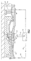
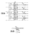
- relatively cool bleed air from an early stage of the high pressure compressor 18 of the gas turbine engine 10 flows through a high pressure compressor bleed manifold 56 and is directed through four bleed pipes 42 (only one is shown in Figures 1 and 2 for simplicity, and all four bleed pipes 42 are shown in Figures 3 and 4 ) located outside a casing 44.
- the cool bleed air is directed to a mid turbine frame 46 and the low pressure turbine 24 to absorb heat from the mid turbine frame 46 and the low pressure turbine 24, therefore cooling these components.
- the mid turbine frame 46 provides support for the rotor 27.
- the heated bleed air is then exhausted into a main gas path 70.
- a cooling system cools the rear rim 38 and the rear hub 40 of the last stage of the high pressure compressor 18.
- the cooling system is integrated with the cooling system including the bleed pipes 42 that transport bleed air that cools the mid turbine frame 46 and the low pressure turbine 24.
- the cooling system is a passive system that results in no negative performance impact.
- the cooling system could also decouple stress limitations of the high pressure compressor 18 from further thermodynamic cycle optimizations.
- Air from a diffuser case 60 located downstream of the compressor exit is directed through four high pressure compressor pipes 52.
- a heat exchanger 50 is integrated on each bleed pipe 42.
- the fluid flowing through the high pressure compressor pipes 52 from the diffuser case 60 exchanges heat with bleed air flowing through the bleed pipes 42 that is directed to the mid turbine frame 46 and the low pressure turbine 24.
- the flow rate of the cooler bleed air is about four times than the flow rate of the hotter air from the high pressure compressor 18.
- the flow and temperature boundary conditions on the hot and cold sides translate into a heat exchanger 50 effectiveness of less than 0.5, which means that the heat exchanger 50 size can be relatively small.
- An airstream 62 is used to ventilate and cool the rear hub 40 of the high pressure compressor 18.
- the airstream 62 is the sum of flow through paths 55 and 54.
- the air that flows through the path 55 is drawn from the diffuser case 60 and directed to the heat exchanger 50 to be cooled ( ⁇ T) approximately 200°F (111°C).
- the air flows through the heat exchanger 50 and exchanges heat with the cooler bleed air flowing through the bleed pipes 42.
- the air is then directed to the rear rim 38.
- the other path 54 is un-cooled and represents the conventional rim ventilation source. Air flow through the path 54 is bled from the inner diameter of the gas path between the blade 34a and the vane 36a into the rear rim 38, where it is combined with the fluid in the path 55.
- the resulting rim cavity air is cooled 100°F (55°C) compared to the uncooled baseline, allowing the rear rim 38 and the rear hub 40 to be cooled ( ⁇ T) by as much as 100°F (55°C). Therefore, by mixing cooled air in the path 55 at the rear rim 38 of the high pressure compressor 18, the life of the gas turbine engine 10 can be increased.
- the air in the airstream 62 is exhausted downstream of the rear hub 40 into the turbine cooling system and cools the hotter sections of the gas turbine engine 10, such as the high pressure turbine 22.
- the fluid in the bleed pipes 42 is directed to the mid turbine frame 46 and the low pressure turbine 24.
- the 200°F (111°C) temperature reduction of the hot air in the path 55 results in an approximately 50°F (28°C) temperature increase of the cooling air in the bleed pipes 42. Therefore, the mid turbine frame 46 and the low pressure turbine 24 are up to 50°F (28°C) warmer ( ⁇ T) than a system that does not employ the heat exchanger 50.
- the four bleed pipes 42 are in fluid communication with a high pressure compressor bleed manifold 56.
- the fluid in each high pressure compressor pipe 52 is fed through a bleed port of the diffuser case 60 and into the heat exchanger 50.
- the heat exchanger 50 is a plate fin heat exchanger. After exchanging heat with the bleed air in the bleed pipes 42, the cooled air exits the heat exchanger 50 through a strut 58 and cools the rear rim 38 and the rear hub 40.
- the struts 58 are integrated with the high pressure compressor pipes 52.
- the four bleed pipes 42 are angularly spaced relative to the high pressure compressor bleed manifold 56 and spaced 90° apart in a circumferential direction.
- the flow of fluid through the heat exchanger 50 is substantially parallel to the diffuser case 60.
- the four bleed pipes 42 are in fluid communication with a high pressure compressor bleed manifold 56.
- the fluid in each high pressure compressor pipe 52 is fed through a bleed port of the diffuser case 60 and into the heat exchanger 50.
- the heat exchanger 50 is a plate fin heat exchanger. After exchanging heat with the bleed air in the bleed pipes 42, the cooled air exits the heat exchanger 50 through two struts 58a and 58b and cools the rear rim 38 and the rear hub 40. This results in a lower pressure drop, which increases the pressure drop available across the heat exchanger 50 and could result in a smaller size heat exchanger.
- the four bleed pipes 42 are angularly spaced relative to the high pressure compressor bleed manifold 56 and spaced 90° apart in a radial direction. Therefore, the bleed pipes 42 each include a right angle bend that allows the pipes 42 to extend in a circumferential direction, as in the example of Figures 3A and 3B .
- the flow of fluid through the heat exchanger 50 is substantially perpendicular to the diffuser case 60.
- the heat exchanger 50 is mounted directly on the bleed port of the diffuser case 60.
- the struts 58a and 58b and the diffuser case 60 extend in the same axial direction.
Landscapes
- Engineering & Computer Science (AREA)
- Mechanical Engineering (AREA)
- General Engineering & Computer Science (AREA)
- Chemical & Material Sciences (AREA)
- Combustion & Propulsion (AREA)
- Physics & Mathematics (AREA)
- Thermal Sciences (AREA)
- Structures Of Non-Positive Displacement Pumps (AREA)
- Turbine Rotor Nozzle Sealing (AREA)
Applications Claiming Priority (1)
| Application Number | Priority Date | Filing Date | Title |
|---|---|---|---|
| US12/757,450 US8256229B2 (en) | 2010-04-09 | 2010-04-09 | Rear hub cooling for high pressure compressor |
Publications (3)
| Publication Number | Publication Date |
|---|---|
| EP2374995A2 true EP2374995A2 (fr) | 2011-10-12 |
| EP2374995A3 EP2374995A3 (fr) | 2014-11-19 |
| EP2374995B1 EP2374995B1 (fr) | 2018-12-26 |
Family
ID=43901457
Family Applications (1)
| Application Number | Title | Priority Date | Filing Date |
|---|---|---|---|
| EP11161124.0A Active EP2374995B1 (fr) | 2010-04-09 | 2011-04-05 | Refroidissement du moyeu arrière d'un compresseur haute pression |
Country Status (2)
| Country | Link |
|---|---|
| US (2) | US8256229B2 (fr) |
| EP (1) | EP2374995B1 (fr) |
Cited By (11)
| Publication number | Priority date | Publication date | Assignee | Title |
|---|---|---|---|---|
| WO2013101805A1 (fr) | 2011-12-27 | 2013-07-04 | United Technologies Corporation | Agencement de compresseur de moteur à turbine à gaz |
| WO2013130307A1 (fr) * | 2012-02-27 | 2013-09-06 | United Technologies Corporation | Système tampon de refroidissement de moteur de turbine à gaz |
| EP2592235A3 (fr) * | 2011-11-11 | 2014-10-15 | United Technologies Corporation | Agencement de compresseur de turbine à gaz |
| US9038398B2 (en) | 2012-02-27 | 2015-05-26 | United Technologies Corporation | Gas turbine engine buffer cooling system |
| US9157325B2 (en) | 2012-02-27 | 2015-10-13 | United Technologies Corporation | Buffer cooling system providing gas turbine engine architecture cooling |
| EP3032031A1 (fr) * | 2014-12-10 | 2016-06-15 | Pratt & Whitney Canada Corp. | Air p3 refroidi modulé pour turbine |
| US9435259B2 (en) | 2012-02-27 | 2016-09-06 | United Technologies Corporation | Gas turbine engine cooling system |
| EP3181869A1 (fr) * | 2015-12-14 | 2017-06-21 | United Technologies Corporation | Refroidissement de diamètre interne de compresseur |
| US10830152B2 (en) | 2007-09-21 | 2020-11-10 | Raytheon Technologies Corporation | Gas turbine engine compressor arrangement |
| US11781506B2 (en) | 2020-06-03 | 2023-10-10 | Rtx Corporation | Splitter and guide vane arrangement for gas turbine engines |
| US12331691B2 (en) | 2011-12-27 | 2025-06-17 | Rtx Corporation | Gas turbine engine compressor arrangement |
Families Citing this family (43)
| Publication number | Priority date | Publication date | Assignee | Title |
|---|---|---|---|---|
| US9410482B2 (en) * | 2010-12-24 | 2016-08-09 | Rolls-Royce North American Technologies, Inc. | Gas turbine engine heat exchanger |
| US9476313B2 (en) | 2012-12-21 | 2016-10-25 | United Technologies Corporation | Gas turbine engine including a pre-diffuser heat exchanger |
| WO2014134519A1 (fr) | 2013-02-28 | 2014-09-04 | United Technologies Corporation | Procédé et appareil pour capter un écoulement d'air de pré-diffuseur et l'acheminer vers des pré-unités de turbulence de chambre à combustion |
| US20150362463A1 (en) | 2013-03-01 | 2015-12-17 | Kyocera Corporation | Sensor |
| EP2971665B1 (fr) | 2013-03-14 | 2020-04-15 | United Technologies Corporation | Diviseur pour collecteur de prélèvement d'air |
| DE102013224982A1 (de) | 2013-12-05 | 2015-06-11 | Rolls-Royce Deutschland Ltd & Co Kg | Fluggasturbine mit einem Kern-Triebwerksgehäuse mit Kühlluftröhren |
| CN104121037B (zh) * | 2014-07-18 | 2015-07-01 | 北京航空航天大学 | 热管涡轮盘 |
| US20170082028A1 (en) * | 2015-02-12 | 2017-03-23 | United Technologies Corporation | Intercooled cooling air using existing heat exchanger |
| US20160237905A1 (en) * | 2015-02-12 | 2016-08-18 | United Technologies Corporation | Intercooled cooling air |
| US10731560B2 (en) * | 2015-02-12 | 2020-08-04 | Raytheon Technologies Corporation | Intercooled cooling air |
| US11808210B2 (en) | 2015-02-12 | 2023-11-07 | Rtx Corporation | Intercooled cooling air with heat exchanger packaging |
| US20160237907A1 (en) * | 2015-02-12 | 2016-08-18 | United Technologies Corporation | Intercooled cooling air with auxiliary compressor control |
| US20160237908A1 (en) * | 2015-02-12 | 2016-08-18 | United Technologies Corporation | Intercooled cooling air using existing heat exchanger |
| US10371055B2 (en) | 2015-02-12 | 2019-08-06 | United Technologies Corporation | Intercooled cooling air using cooling compressor as starter |
| US10480419B2 (en) | 2015-04-24 | 2019-11-19 | United Technologies Corporation | Intercooled cooling air with plural heat exchangers |
| US10830148B2 (en) | 2015-04-24 | 2020-11-10 | Raytheon Technologies Corporation | Intercooled cooling air with dual pass heat exchanger |
| US10221862B2 (en) | 2015-04-24 | 2019-03-05 | United Technologies Corporation | Intercooled cooling air tapped from plural locations |
| US10100739B2 (en) | 2015-05-18 | 2018-10-16 | United Technologies Corporation | Cooled cooling air system for a gas turbine engine |
| US10794288B2 (en) | 2015-07-07 | 2020-10-06 | Raytheon Technologies Corporation | Cooled cooling air system for a turbofan engine |
| US10443508B2 (en) | 2015-12-14 | 2019-10-15 | United Technologies Corporation | Intercooled cooling air with auxiliary compressor control |
| US10669940B2 (en) | 2016-09-19 | 2020-06-02 | Raytheon Technologies Corporation | Gas turbine engine with intercooled cooling air and turbine drive |
| US10794290B2 (en) | 2016-11-08 | 2020-10-06 | Raytheon Technologies Corporation | Intercooled cooled cooling integrated air cycle machine |
| US10550768B2 (en) | 2016-11-08 | 2020-02-04 | United Technologies Corporation | Intercooled cooled cooling integrated air cycle machine |
| US10961911B2 (en) | 2017-01-17 | 2021-03-30 | Raytheon Technologies Corporation | Injection cooled cooling air system for a gas turbine engine |
| US10995673B2 (en) | 2017-01-19 | 2021-05-04 | Raytheon Technologies Corporation | Gas turbine engine with intercooled cooling air and dual towershaft accessory gearbox |
| US10577964B2 (en) | 2017-03-31 | 2020-03-03 | United Technologies Corporation | Cooled cooling air for blade air seal through outer chamber |
| US10711640B2 (en) | 2017-04-11 | 2020-07-14 | Raytheon Technologies Corporation | Cooled cooling air to blade outer air seal passing through a static vane |
| US11377957B2 (en) | 2017-05-09 | 2022-07-05 | General Electric Company | Gas turbine engine with a diffuser cavity cooled compressor |
| US11022037B2 (en) | 2018-01-04 | 2021-06-01 | General Electric Company | Gas turbine engine thermal management system |
| US10941706B2 (en) | 2018-02-13 | 2021-03-09 | General Electric Company | Closed cycle heat engine for a gas turbine engine |
| US11143104B2 (en) | 2018-02-20 | 2021-10-12 | General Electric Company | Thermal management system |
| US10746098B2 (en) | 2018-03-09 | 2020-08-18 | General Electric Company | Compressor rotor cooling apparatus |
| US10738703B2 (en) | 2018-03-22 | 2020-08-11 | Raytheon Technologies Corporation | Intercooled cooling air with combined features |
| US10830145B2 (en) | 2018-04-19 | 2020-11-10 | Raytheon Technologies Corporation | Intercooled cooling air fleet management system |
| US10808619B2 (en) | 2018-04-19 | 2020-10-20 | Raytheon Technologies Corporation | Intercooled cooling air with advanced cooling system |
| US10718233B2 (en) | 2018-06-19 | 2020-07-21 | Raytheon Technologies Corporation | Intercooled cooling air with low temperature bearing compartment air |
| US11255268B2 (en) | 2018-07-31 | 2022-02-22 | Raytheon Technologies Corporation | Intercooled cooling air with selective pressure dump |
| US10823069B2 (en) | 2018-11-09 | 2020-11-03 | Raytheon Technologies Corporation | Internal heat exchanger system to cool gas turbine engine components |
| US11015534B2 (en) | 2018-11-28 | 2021-05-25 | General Electric Company | Thermal management system |
| US11674396B2 (en) | 2021-07-30 | 2023-06-13 | General Electric Company | Cooling air delivery assembly |
| US20250347258A1 (en) * | 2024-04-24 | 2025-11-13 | General Electric Company | Gas turbine engine having cooling systems |
| US20250347252A1 (en) * | 2024-04-24 | 2025-11-13 | General Electric Company | Gas turbine engine having cooling systems |
| US20250347251A1 (en) * | 2024-04-24 | 2025-11-13 | General Electric Company | Gas turbine engine having cooling systems |
Family Cites Families (19)
| Publication number | Priority date | Publication date | Assignee | Title |
|---|---|---|---|---|
| US4055946A (en) | 1976-03-29 | 1977-11-01 | United Technologies Corporation | Twin-spool gas turbine power plant with means to spill compressor interstage airflow |
| US4254618A (en) * | 1977-08-18 | 1981-03-10 | General Electric Company | Cooling air cooler for a gas turbofan engine |
| DE3638960C1 (de) | 1986-11-14 | 1988-04-28 | Mtu Muenchen Gmbh | Gasturbinenstrahltriebwerk mit einem gekuehlten Hochdruckverdichter |
| DE3638961A1 (de) | 1986-11-14 | 1988-05-26 | Mtu Muenchen Gmbh | Gasturbinentriebwerk mit einem hochdruckverdichter |
| US5209633A (en) | 1990-11-19 | 1993-05-11 | General Electric Company | High pressure compressor flowpath bleed valve extraction slot |
| US5392614A (en) * | 1992-03-23 | 1995-02-28 | General Electric Company | Gas turbine engine cooling system |
| FR2695161B1 (fr) * | 1992-08-26 | 1994-11-04 | Snecma | Système de refroidissement d'un compresseur de turbomachine et de contrôle des jeux. |
| US5292227A (en) * | 1992-12-10 | 1994-03-08 | General Electric Company | Turbine frame |
| US5414992A (en) * | 1993-08-06 | 1995-05-16 | United Technologies Corporation | Aircraft cooling method |
| US5697208A (en) * | 1995-06-02 | 1997-12-16 | Solar Turbines Incorporated | Turbine cooling cycle |
| US5724806A (en) | 1995-09-11 | 1998-03-10 | General Electric Company | Extracted, cooled, compressed/intercooled, cooling/combustion air for a gas turbine engine |
| US6134880A (en) | 1997-12-31 | 2000-10-24 | Concepts Eti, Inc. | Turbine engine with intercooler in bypass air passage |
| US6250061B1 (en) | 1999-03-02 | 2001-06-26 | General Electric Company | Compressor system and methods for reducing cooling airflow |
| DE10009655C1 (de) * | 2000-02-29 | 2001-05-23 | Mtu Aero Engines Gmbh | Kühlluftsystem |
| US6722138B2 (en) | 2000-12-13 | 2004-04-20 | United Technologies Corporation | Vane platform trailing edge cooling |
| FR2858358B1 (fr) * | 2003-07-28 | 2005-09-23 | Snecma Moteurs | Procede de refroidissement, par air refroidi en partie dans un echangeur externe, des parties chaudes d'un turboreacteur, et turboreacteur ainsi refroidi |
| US7124590B2 (en) | 2003-10-03 | 2006-10-24 | United Technologies Corporation | Ejector for cooling air supply pressure optimization |
| FR2914017B1 (fr) * | 2007-03-20 | 2011-07-08 | Snecma | Dispositif d'etancheite pour un circuit de refroidissement, carter inter-turbine en etant equipe et turboreacteur les comportant |
| US8056345B2 (en) * | 2007-06-13 | 2011-11-15 | United Technologies Corporation | Hybrid cooling of a gas turbine engine |
-
2010
- 2010-04-09 US US12/757,450 patent/US8256229B2/en active Active
-
2011
- 2011-04-05 EP EP11161124.0A patent/EP2374995B1/fr active Active
-
2012
- 2012-07-09 US US13/544,108 patent/US8459040B2/en active Active
Non-Patent Citations (1)
| Title |
|---|
| None |
Cited By (21)
| Publication number | Priority date | Publication date | Assignee | Title |
|---|---|---|---|---|
| US12085025B2 (en) | 2007-09-21 | 2024-09-10 | Rtx Corporation | Gas turbine engine compressor arrangement |
| US10830152B2 (en) | 2007-09-21 | 2020-11-10 | Raytheon Technologies Corporation | Gas turbine engine compressor arrangement |
| EP2592235A3 (fr) * | 2011-11-11 | 2014-10-15 | United Technologies Corporation | Agencement de compresseur de turbine à gaz |
| US12331691B2 (en) | 2011-12-27 | 2025-06-17 | Rtx Corporation | Gas turbine engine compressor arrangement |
| EP2776677A4 (fr) * | 2011-12-27 | 2014-10-08 | United Technologies Corp | Agencement de compresseur de moteur à turbine à gaz |
| EP2937509A1 (fr) * | 2011-12-27 | 2015-10-28 | United Technologies Corporation | Agencement de compresseur de turbine à gaz |
| CN103764952B (zh) * | 2011-12-27 | 2016-06-08 | 联合工艺公司 | 燃气涡轮发动机压缩机装置 |
| WO2013101805A1 (fr) | 2011-12-27 | 2013-07-04 | United Technologies Corporation | Agencement de compresseur de moteur à turbine à gaz |
| CN103764952A (zh) * | 2011-12-27 | 2014-04-30 | 联合工艺公司 | 燃气涡轮发动机压缩机装置 |
| JP2019190467A (ja) * | 2011-12-27 | 2019-10-31 | ユナイテッド テクノロジーズ コーポレイションUnited Technologies Corporation | ガスタービンエンジン |
| US9038398B2 (en) | 2012-02-27 | 2015-05-26 | United Technologies Corporation | Gas turbine engine buffer cooling system |
| US9157325B2 (en) | 2012-02-27 | 2015-10-13 | United Technologies Corporation | Buffer cooling system providing gas turbine engine architecture cooling |
| US9347374B2 (en) | 2012-02-27 | 2016-05-24 | United Technologies Corporation | Gas turbine engine buffer cooling system |
| US9435259B2 (en) | 2012-02-27 | 2016-09-06 | United Technologies Corporation | Gas turbine engine cooling system |
| US9976485B2 (en) | 2012-02-27 | 2018-05-22 | United Technologies Corporation | Gas turbine engine buffer cooling system |
| WO2013130307A1 (fr) * | 2012-02-27 | 2013-09-06 | United Technologies Corporation | Système tampon de refroidissement de moteur de turbine à gaz |
| EP3032031A1 (fr) * | 2014-12-10 | 2016-06-15 | Pratt & Whitney Canada Corp. | Air p3 refroidi modulé pour turbine |
| US10767562B2 (en) | 2014-12-10 | 2020-09-08 | Pratt & Whitney Canada Corp. | Modulated cooled P3 air for impeller |
| EP3181869A1 (fr) * | 2015-12-14 | 2017-06-21 | United Technologies Corporation | Refroidissement de diamètre interne de compresseur |
| US11781506B2 (en) | 2020-06-03 | 2023-10-10 | Rtx Corporation | Splitter and guide vane arrangement for gas turbine engines |
| US12385449B2 (en) | 2020-06-03 | 2025-08-12 | Rtx Corporation | Splitter and guide vane arrangement for gas turbine engines |
Also Published As
| Publication number | Publication date |
|---|---|
| EP2374995A3 (fr) | 2014-11-19 |
| EP2374995B1 (fr) | 2018-12-26 |
| US20110247344A1 (en) | 2011-10-13 |
| US8459040B2 (en) | 2013-06-11 |
| US20120282079A1 (en) | 2012-11-08 |
| US8256229B2 (en) | 2012-09-04 |
Similar Documents
| Publication | Publication Date | Title |
|---|---|---|
| EP2374995B1 (fr) | Refroidissement du moyeu arrière d'un compresseur haute pression | |
| JP6746335B2 (ja) | ターボ機械のためのヒートパイプ温度管理システム | |
| US9976485B2 (en) | Gas turbine engine buffer cooling system | |
| US9157325B2 (en) | Buffer cooling system providing gas turbine engine architecture cooling | |
| US9347374B2 (en) | Gas turbine engine buffer cooling system | |
| US7966807B2 (en) | Vapor cooled static turbine hardware | |
| US8763363B2 (en) | Method and system for cooling fluid in a turbine engine | |
| US20160290235A1 (en) | Heat pipe temperature management system for a turbomachine | |
| CN106884723A (zh) | 利用热管用于燃气涡轮发动机的闭环冷却方法和系统 | |
| EP3075983A1 (fr) | Échangeur de chaleur carburant pour air de refroidissement d'un moteur à turbine à gaz refroidi | |
| CN106988887A (zh) | 燃气涡轮发动机流体冷却系统及其组装方法 | |
| EP2820253B1 (fr) | Moteur à turbine à gaz | |
| JP2017020493A (ja) | タービンバンドのアンチコーディングフランジ | |
| EP3354851B1 (fr) | Refroidissement de surface portante hybride | |
| CN106050313A (zh) | 用于涡轮机中的叶轮和轮叶的热管温度管理系统 | |
| EP3277940B1 (fr) | Système de gestion de température de caloduc pour roues et aubes dans une turbomachine | |
| US11248486B2 (en) | Aircraft turbine-engine module casing, comprising a heat pipe associated with a sealing ring surrounding a movable impeller of the module | |
| EP3901411B1 (fr) | Système de gestion thermique pour un composant d'un moteur à turbine à gaz |
Legal Events
| Date | Code | Title | Description |
|---|---|---|---|
| PUAI | Public reference made under article 153(3) epc to a published international application that has entered the european phase |
Free format text: ORIGINAL CODE: 0009012 |
|
| AK | Designated contracting states |
Kind code of ref document: A2 Designated state(s): AL AT BE BG CH CY CZ DE DK EE ES FI FR GB GR HR HU IE IS IT LI LT LU LV MC MK MT NL NO PL PT RO RS SE SI SK SM TR |
|
| AX | Request for extension of the european patent |
Extension state: BA ME |
|
| PUAL | Search report despatched |
Free format text: ORIGINAL CODE: 0009013 |
|
| AK | Designated contracting states |
Kind code of ref document: A3 Designated state(s): AL AT BE BG CH CY CZ DE DK EE ES FI FR GB GR HR HU IE IS IT LI LT LU LV MC MK MT NL NO PL PT RO RS SE SI SK SM TR |
|
| AX | Request for extension of the european patent |
Extension state: BA ME |
|
| RIC1 | Information provided on ipc code assigned before grant |
Ipc: F02C 7/143 20060101AFI20141015BHEP Ipc: F02C 7/18 20060101ALN20141015BHEP Ipc: F02C 6/08 20060101ALI20141015BHEP Ipc: F04D 29/32 20060101ALI20141015BHEP Ipc: F04D 29/58 20060101ALI20141015BHEP Ipc: F01D 5/08 20060101ALN20141015BHEP |
|
| 17P | Request for examination filed |
Effective date: 20150519 |
|
| RBV | Designated contracting states (corrected) |
Designated state(s): AL AT BE BG CH CY CZ DE DK EE ES FI FR GB GR HR HU IE IS IT LI LT LU LV MC MK MT NL NO PL PT RO RS SE SI SK SM TR |
|
| 17Q | First examination report despatched |
Effective date: 20160721 |
|
| RAP1 | Party data changed (applicant data changed or rights of an application transferred) |
Owner name: UNITED TECHNOLOGIES CORPORATION |
|
| STAA | Information on the status of an ep patent application or granted ep patent |
Free format text: STATUS: EXAMINATION IS IN PROGRESS |
|
| REG | Reference to a national code |
Ref country code: DE Ref legal event code: R079 Ref document number: 602011055063 Country of ref document: DE Free format text: PREVIOUS MAIN CLASS: F01D0005080000 Ipc: F02C0007143000 |
|
| GRAP | Despatch of communication of intention to grant a patent |
Free format text: ORIGINAL CODE: EPIDOSNIGR1 |
|
| STAA | Information on the status of an ep patent application or granted ep patent |
Free format text: STATUS: GRANT OF PATENT IS INTENDED |
|
| RIC1 | Information provided on ipc code assigned before grant |
Ipc: F02C 7/143 20060101AFI20180629BHEP Ipc: F04D 29/58 20060101ALI20180629BHEP Ipc: F01D 5/08 20060101ALN20180629BHEP Ipc: F02C 6/08 20060101ALI20180629BHEP Ipc: F02C 7/18 20060101ALN20180629BHEP Ipc: F04D 29/32 20060101ALI20180629BHEP |
|
| INTG | Intention to grant announced |
Effective date: 20180717 |
|
| GRAS | Grant fee paid |
Free format text: ORIGINAL CODE: EPIDOSNIGR3 |
|
| GRAA | (expected) grant |
Free format text: ORIGINAL CODE: 0009210 |
|
| STAA | Information on the status of an ep patent application or granted ep patent |
Free format text: STATUS: THE PATENT HAS BEEN GRANTED |
|
| AK | Designated contracting states |
Kind code of ref document: B1 Designated state(s): AL AT BE BG CH CY CZ DE DK EE ES FI FR GB GR HR HU IE IS IT LI LT LU LV MC MK MT NL NO PL PT RO RS SE SI SK SM TR |
|
| REG | Reference to a national code |
Ref country code: GB Ref legal event code: FG4D |
|
| REG | Reference to a national code |
Ref country code: CH Ref legal event code: EP |
|
| REG | Reference to a national code |
Ref country code: AT Ref legal event code: REF Ref document number: 1081740 Country of ref document: AT Kind code of ref document: T Effective date: 20190115 |
|
| REG | Reference to a national code |
Ref country code: DE Ref legal event code: R096 Ref document number: 602011055063 Country of ref document: DE |
|
| REG | Reference to a national code |
Ref country code: IE Ref legal event code: FG4D |
|
| PG25 | Lapsed in a contracting state [announced via postgrant information from national office to epo] |
Ref country code: BG Free format text: LAPSE BECAUSE OF FAILURE TO SUBMIT A TRANSLATION OF THE DESCRIPTION OR TO PAY THE FEE WITHIN THE PRESCRIBED TIME-LIMIT Effective date: 20190326 Ref country code: FI Free format text: LAPSE BECAUSE OF FAILURE TO SUBMIT A TRANSLATION OF THE DESCRIPTION OR TO PAY THE FEE WITHIN THE PRESCRIBED TIME-LIMIT Effective date: 20181226 Ref country code: LV Free format text: LAPSE BECAUSE OF FAILURE TO SUBMIT A TRANSLATION OF THE DESCRIPTION OR TO PAY THE FEE WITHIN THE PRESCRIBED TIME-LIMIT Effective date: 20181226 Ref country code: HR Free format text: LAPSE BECAUSE OF FAILURE TO SUBMIT A TRANSLATION OF THE DESCRIPTION OR TO PAY THE FEE WITHIN THE PRESCRIBED TIME-LIMIT Effective date: 20181226 Ref country code: NO Free format text: LAPSE BECAUSE OF FAILURE TO SUBMIT A TRANSLATION OF THE DESCRIPTION OR TO PAY THE FEE WITHIN THE PRESCRIBED TIME-LIMIT Effective date: 20190326 Ref country code: LT Free format text: LAPSE BECAUSE OF FAILURE TO SUBMIT A TRANSLATION OF THE DESCRIPTION OR TO PAY THE FEE WITHIN THE PRESCRIBED TIME-LIMIT Effective date: 20181226 |
|
| REG | Reference to a national code |
Ref country code: NL Ref legal event code: MP Effective date: 20181226 |
|
| REG | Reference to a national code |
Ref country code: LT Ref legal event code: MG4D |
|
| PG25 | Lapsed in a contracting state [announced via postgrant information from national office to epo] |
Ref country code: GR Free format text: LAPSE BECAUSE OF FAILURE TO SUBMIT A TRANSLATION OF THE DESCRIPTION OR TO PAY THE FEE WITHIN THE PRESCRIBED TIME-LIMIT Effective date: 20190327 Ref country code: RS Free format text: LAPSE BECAUSE OF FAILURE TO SUBMIT A TRANSLATION OF THE DESCRIPTION OR TO PAY THE FEE WITHIN THE PRESCRIBED TIME-LIMIT Effective date: 20181226 Ref country code: SE Free format text: LAPSE BECAUSE OF FAILURE TO SUBMIT A TRANSLATION OF THE DESCRIPTION OR TO PAY THE FEE WITHIN THE PRESCRIBED TIME-LIMIT Effective date: 20181226 Ref country code: AL Free format text: LAPSE BECAUSE OF FAILURE TO SUBMIT A TRANSLATION OF THE DESCRIPTION OR TO PAY THE FEE WITHIN THE PRESCRIBED TIME-LIMIT Effective date: 20181226 |
|
| REG | Reference to a national code |
Ref country code: AT Ref legal event code: MK05 Ref document number: 1081740 Country of ref document: AT Kind code of ref document: T Effective date: 20181226 |
|
| PG25 | Lapsed in a contracting state [announced via postgrant information from national office to epo] |
Ref country code: NL Free format text: LAPSE BECAUSE OF FAILURE TO SUBMIT A TRANSLATION OF THE DESCRIPTION OR TO PAY THE FEE WITHIN THE PRESCRIBED TIME-LIMIT Effective date: 20181226 |
|
| PG25 | Lapsed in a contracting state [announced via postgrant information from national office to epo] |
Ref country code: IT Free format text: LAPSE BECAUSE OF FAILURE TO SUBMIT A TRANSLATION OF THE DESCRIPTION OR TO PAY THE FEE WITHIN THE PRESCRIBED TIME-LIMIT Effective date: 20181226 Ref country code: ES Free format text: LAPSE BECAUSE OF FAILURE TO SUBMIT A TRANSLATION OF THE DESCRIPTION OR TO PAY THE FEE WITHIN THE PRESCRIBED TIME-LIMIT Effective date: 20181226 Ref country code: PT Free format text: LAPSE BECAUSE OF FAILURE TO SUBMIT A TRANSLATION OF THE DESCRIPTION OR TO PAY THE FEE WITHIN THE PRESCRIBED TIME-LIMIT Effective date: 20190426 Ref country code: CZ Free format text: LAPSE BECAUSE OF FAILURE TO SUBMIT A TRANSLATION OF THE DESCRIPTION OR TO PAY THE FEE WITHIN THE PRESCRIBED TIME-LIMIT Effective date: 20181226 Ref country code: PL Free format text: LAPSE BECAUSE OF FAILURE TO SUBMIT A TRANSLATION OF THE DESCRIPTION OR TO PAY THE FEE WITHIN THE PRESCRIBED TIME-LIMIT Effective date: 20181226 |
|
| PG25 | Lapsed in a contracting state [announced via postgrant information from national office to epo] |
Ref country code: SM Free format text: LAPSE BECAUSE OF FAILURE TO SUBMIT A TRANSLATION OF THE DESCRIPTION OR TO PAY THE FEE WITHIN THE PRESCRIBED TIME-LIMIT Effective date: 20181226 Ref country code: EE Free format text: LAPSE BECAUSE OF FAILURE TO SUBMIT A TRANSLATION OF THE DESCRIPTION OR TO PAY THE FEE WITHIN THE PRESCRIBED TIME-LIMIT Effective date: 20181226 Ref country code: SK Free format text: LAPSE BECAUSE OF FAILURE TO SUBMIT A TRANSLATION OF THE DESCRIPTION OR TO PAY THE FEE WITHIN THE PRESCRIBED TIME-LIMIT Effective date: 20181226 Ref country code: RO Free format text: LAPSE BECAUSE OF FAILURE TO SUBMIT A TRANSLATION OF THE DESCRIPTION OR TO PAY THE FEE WITHIN THE PRESCRIBED TIME-LIMIT Effective date: 20181226 Ref country code: IS Free format text: LAPSE BECAUSE OF FAILURE TO SUBMIT A TRANSLATION OF THE DESCRIPTION OR TO PAY THE FEE WITHIN THE PRESCRIBED TIME-LIMIT Effective date: 20190426 |
|
| REG | Reference to a national code |
Ref country code: DE Ref legal event code: R097 Ref document number: 602011055063 Country of ref document: DE |
|
| PG25 | Lapsed in a contracting state [announced via postgrant information from national office to epo] |
Ref country code: DK Free format text: LAPSE BECAUSE OF FAILURE TO SUBMIT A TRANSLATION OF THE DESCRIPTION OR TO PAY THE FEE WITHIN THE PRESCRIBED TIME-LIMIT Effective date: 20181226 Ref country code: AT Free format text: LAPSE BECAUSE OF FAILURE TO SUBMIT A TRANSLATION OF THE DESCRIPTION OR TO PAY THE FEE WITHIN THE PRESCRIBED TIME-LIMIT Effective date: 20181226 |
|
| PLBE | No opposition filed within time limit |
Free format text: ORIGINAL CODE: 0009261 |
|
| STAA | Information on the status of an ep patent application or granted ep patent |
Free format text: STATUS: NO OPPOSITION FILED WITHIN TIME LIMIT |
|
| REG | Reference to a national code |
Ref country code: CH Ref legal event code: PL |
|
| 26N | No opposition filed |
Effective date: 20190927 |
|
| REG | Reference to a national code |
Ref country code: BE Ref legal event code: MM Effective date: 20190430 |
|
| PG25 | Lapsed in a contracting state [announced via postgrant information from national office to epo] |
Ref country code: MC Free format text: LAPSE BECAUSE OF FAILURE TO SUBMIT A TRANSLATION OF THE DESCRIPTION OR TO PAY THE FEE WITHIN THE PRESCRIBED TIME-LIMIT Effective date: 20181226 Ref country code: LU Free format text: LAPSE BECAUSE OF NON-PAYMENT OF DUE FEES Effective date: 20190405 |
|
| PG25 | Lapsed in a contracting state [announced via postgrant information from national office to epo] |
Ref country code: LI Free format text: LAPSE BECAUSE OF NON-PAYMENT OF DUE FEES Effective date: 20190430 Ref country code: CH Free format text: LAPSE BECAUSE OF NON-PAYMENT OF DUE FEES Effective date: 20190430 |
|
| PG25 | Lapsed in a contracting state [announced via postgrant information from national office to epo] |
Ref country code: BE Free format text: LAPSE BECAUSE OF NON-PAYMENT OF DUE FEES Effective date: 20190430 Ref country code: FR Free format text: LAPSE BECAUSE OF NON-PAYMENT OF DUE FEES Effective date: 20190430 Ref country code: SI Free format text: LAPSE BECAUSE OF FAILURE TO SUBMIT A TRANSLATION OF THE DESCRIPTION OR TO PAY THE FEE WITHIN THE PRESCRIBED TIME-LIMIT Effective date: 20181226 |
|
| PG25 | Lapsed in a contracting state [announced via postgrant information from national office to epo] |
Ref country code: TR Free format text: LAPSE BECAUSE OF FAILURE TO SUBMIT A TRANSLATION OF THE DESCRIPTION OR TO PAY THE FEE WITHIN THE PRESCRIBED TIME-LIMIT Effective date: 20181226 |
|
| PG25 | Lapsed in a contracting state [announced via postgrant information from national office to epo] |
Ref country code: IE Free format text: LAPSE BECAUSE OF NON-PAYMENT OF DUE FEES Effective date: 20190405 |
|
| PG25 | Lapsed in a contracting state [announced via postgrant information from national office to epo] |
Ref country code: CY Free format text: LAPSE BECAUSE OF FAILURE TO SUBMIT A TRANSLATION OF THE DESCRIPTION OR TO PAY THE FEE WITHIN THE PRESCRIBED TIME-LIMIT Effective date: 20181226 |
|
| PG25 | Lapsed in a contracting state [announced via postgrant information from national office to epo] |
Ref country code: MT Free format text: LAPSE BECAUSE OF FAILURE TO SUBMIT A TRANSLATION OF THE DESCRIPTION OR TO PAY THE FEE WITHIN THE PRESCRIBED TIME-LIMIT Effective date: 20181226 Ref country code: HU Free format text: LAPSE BECAUSE OF FAILURE TO SUBMIT A TRANSLATION OF THE DESCRIPTION OR TO PAY THE FEE WITHIN THE PRESCRIBED TIME-LIMIT; INVALID AB INITIO Effective date: 20110405 |
|
| PG25 | Lapsed in a contracting state [announced via postgrant information from national office to epo] |
Ref country code: MK Free format text: LAPSE BECAUSE OF FAILURE TO SUBMIT A TRANSLATION OF THE DESCRIPTION OR TO PAY THE FEE WITHIN THE PRESCRIBED TIME-LIMIT Effective date: 20181226 |
|
| REG | Reference to a national code |
Ref country code: DE Ref legal event code: R081 Ref document number: 602011055063 Country of ref document: DE Owner name: RAYTHEON TECHNOLOGIES CORPORATION (N.D.GES.D.S, US Free format text: FORMER OWNER: UNITED TECHNOLOGIES CORPORATION, FARMINGTON, CONN., US Ref country code: DE Ref legal event code: R081 Ref document number: 602011055063 Country of ref document: DE Owner name: RTX CORPORATION (N.D.GES.D. STAATES DELAWARE),, US Free format text: FORMER OWNER: UNITED TECHNOLOGIES CORPORATION, FARMINGTON, CONN., US |
|
| P01 | Opt-out of the competence of the unified patent court (upc) registered |
Effective date: 20230519 |
|
| PGFP | Annual fee paid to national office [announced via postgrant information from national office to epo] |
Ref country code: DE Payment date: 20250319 Year of fee payment: 15 |
|
| REG | Reference to a national code |
Ref country code: DE Ref legal event code: R081 Ref document number: 602011055063 Country of ref document: DE Owner name: RTX CORPORATION (N.D.GES.D. STAATES DELAWARE),, US Free format text: FORMER OWNER: RAYTHEON TECHNOLOGIES CORPORATION (N.D.GES.D.STAATES DELAWARE), ARLINGTON, VA, US |
|
| PGFP | Annual fee paid to national office [announced via postgrant information from national office to epo] |
Ref country code: GB Payment date: 20260320 Year of fee payment: 16 |