EP2375000B2 - Joint d'arbre - Google Patents
Joint d'arbre Download PDFInfo
- Publication number
- EP2375000B2 EP2375000B2 EP11159510.4A EP11159510A EP2375000B2 EP 2375000 B2 EP2375000 B2 EP 2375000B2 EP 11159510 A EP11159510 A EP 11159510A EP 2375000 B2 EP2375000 B2 EP 2375000B2
- Authority
- EP
- European Patent Office
- Prior art keywords
- shaft
- bearing housing
- oil
- seal
- bearing
- Prior art date
- Legal status (The legal status is an assumption and is not a legal conclusion. Google has not performed a legal analysis and makes no representation as to the accuracy of the status listed.)
- Active
Links
Images


Classifications
-
- F—MECHANICAL ENGINEERING; LIGHTING; HEATING; WEAPONS; BLASTING
- F02—COMBUSTION ENGINES; HOT-GAS OR COMBUSTION-PRODUCT ENGINE PLANTS
- F02B—INTERNAL-COMBUSTION PISTON ENGINES; COMBUSTION ENGINES IN GENERAL
- F02B39/00—Component parts, details, or accessories relating to, driven charging or scavenging pumps, not provided for in groups F02B33/00 - F02B37/00
-
- F—MECHANICAL ENGINEERING; LIGHTING; HEATING; WEAPONS; BLASTING
- F01—MACHINES OR ENGINES IN GENERAL; ENGINE PLANTS IN GENERAL; STEAM ENGINES
- F01D—NON-POSITIVE DISPLACEMENT MACHINES OR ENGINES, e.g. STEAM TURBINES
- F01D11/00—Preventing or minimising internal leakage of working-fluid, e.g. between stages
- F01D11/003—Preventing or minimising internal leakage of working-fluid, e.g. between stages by packing rings; Mechanical seals
-
- F—MECHANICAL ENGINEERING; LIGHTING; HEATING; WEAPONS; BLASTING
- F01—MACHINES OR ENGINES IN GENERAL; ENGINE PLANTS IN GENERAL; STEAM ENGINES
- F01D—NON-POSITIVE DISPLACEMENT MACHINES OR ENGINES, e.g. STEAM TURBINES
- F01D25/00—Component parts, details, or accessories, not provided for in, or of interest apart from, other groups
- F01D25/08—Cooling; Heating; Heat-insulation
- F01D25/12—Cooling
- F01D25/125—Cooling of bearings
-
- F—MECHANICAL ENGINEERING; LIGHTING; HEATING; WEAPONS; BLASTING
- F01—MACHINES OR ENGINES IN GENERAL; ENGINE PLANTS IN GENERAL; STEAM ENGINES
- F01D—NON-POSITIVE DISPLACEMENT MACHINES OR ENGINES, e.g. STEAM TURBINES
- F01D25/00—Component parts, details, or accessories, not provided for in, or of interest apart from, other groups
- F01D25/16—Arrangement of bearings; Supporting or mounting bearings in casings
-
- F—MECHANICAL ENGINEERING; LIGHTING; HEATING; WEAPONS; BLASTING
- F01—MACHINES OR ENGINES IN GENERAL; ENGINE PLANTS IN GENERAL; STEAM ENGINES
- F01D—NON-POSITIVE DISPLACEMENT MACHINES OR ENGINES, e.g. STEAM TURBINES
- F01D25/00—Component parts, details, or accessories, not provided for in, or of interest apart from, other groups
- F01D25/18—Lubricating arrangements
-
- F—MECHANICAL ENGINEERING; LIGHTING; HEATING; WEAPONS; BLASTING
- F01—MACHINES OR ENGINES IN GENERAL; ENGINE PLANTS IN GENERAL; STEAM ENGINES
- F01D—NON-POSITIVE DISPLACEMENT MACHINES OR ENGINES, e.g. STEAM TURBINES
- F01D25/00—Component parts, details, or accessories, not provided for in, or of interest apart from, other groups
- F01D25/18—Lubricating arrangements
- F01D25/183—Sealing means
-
- F—MECHANICAL ENGINEERING; LIGHTING; HEATING; WEAPONS; BLASTING
- F02—COMBUSTION ENGINES; HOT-GAS OR COMBUSTION-PRODUCT ENGINE PLANTS
- F02B—INTERNAL-COMBUSTION PISTON ENGINES; COMBUSTION ENGINES IN GENERAL
- F02B39/00—Component parts, details, or accessories relating to, driven charging or scavenging pumps, not provided for in groups F02B33/00 - F02B37/00
- F02B39/14—Lubrication of pumps; Safety measures therefor
-
- F—MECHANICAL ENGINEERING; LIGHTING; HEATING; WEAPONS; BLASTING
- F05—INDEXING SCHEMES RELATING TO ENGINES OR PUMPS IN VARIOUS SUBCLASSES OF CLASSES F01-F04
- F05D—INDEXING SCHEME FOR ASPECTS RELATING TO NON-POSITIVE-DISPLACEMENT MACHINES OR ENGINES, GAS-TURBINES OR JET-PROPULSION PLANTS
- F05D2220/00—Application
- F05D2220/40—Application in turbochargers
-
- F—MECHANICAL ENGINEERING; LIGHTING; HEATING; WEAPONS; BLASTING
- F05—INDEXING SCHEMES RELATING TO ENGINES OR PUMPS IN VARIOUS SUBCLASSES OF CLASSES F01-F04
- F05D—INDEXING SCHEME FOR ASPECTS RELATING TO NON-POSITIVE-DISPLACEMENT MACHINES OR ENGINES, GAS-TURBINES OR JET-PROPULSION PLANTS
- F05D2240/00—Components
- F05D2240/55—Seals
- F05D2240/58—Piston ring seals
-
- F—MECHANICAL ENGINEERING; LIGHTING; HEATING; WEAPONS; BLASTING
- F05—INDEXING SCHEMES RELATING TO ENGINES OR PUMPS IN VARIOUS SUBCLASSES OF CLASSES F01-F04
- F05D—INDEXING SCHEME FOR ASPECTS RELATING TO NON-POSITIVE-DISPLACEMENT MACHINES OR ENGINES, GAS-TURBINES OR JET-PROPULSION PLANTS
- F05D2260/00—Function
- F05D2260/20—Heat transfer, e.g. cooling
- F05D2260/205—Cooling fluid recirculation, i.e. after cooling one or more components is the cooling fluid recovered and used elsewhere for other purposes
Definitions
- the invention relates to the field of turbomachines, in particular exhaust gas turbochargers subjected to exhaust gases from internal combustion engines.
- exhaust gas turbochargers are used as standard today, with a turbine in the exhaust gas tract of the internal combustion engine and with a compressor upstream of the internal combustion engine, which is connected to the turbine via a common shaft.
- an internal combustion engine is charged using an exhaust gas turbocharger, the filling quantity and thus the fuel mixture in the cylinders is increased, resulting in a noticeable increase in engine performance.
- the energy contained in the exhaust gas of a combustion engine can be converted into electrical or mechanical energy using a power turbine.
- a generator or a mechanical consumer is connected to the turbine shaft.
- a standard exhaust gas turbocharger consists of a rotor consisting of a shaft, a compressor wheel and a turbine wheel, a bearing for the shaft, flow-guiding housing parts (compressor housing or turbine housing) and the bearing housing.
- the shaft of the exhaust gas turbocharger must be sealed off from the cavity of the bearing housing with a suitable sealing concept.
- the internal pressure in the cavity of the bearing housing is usually equal to atmospheric pressure.
- the gas pressure in the flow channel on the compressor or turbine side depends on the current operating point of the exhaust gas turbocharger and is above the pressure in the cavity of the bearing housing at most operating points. In certain cases, however, a negative pressure is also to be expected, e.g. in partial load operation or at standstill.
- a turbine-side shaft seal of an exhaust gas turbocharger which consists of a simple oil collecting chamber on the turbine side of the radial bearing and a piston ring with a sealing effect between the shaft and the bearing housing.
- the bearing oil escaping axially from the radial bearing sprays onto the rotating shaft shoulder, which is offset outwards and is flung into the oil collection chamber by centrifugal forces.
- the bearing oil thrown off in this way then flows downwards within the oil collection chamber under the force of gravity and back into the oil circuit for bearing lubrication.
- Piston rings made of metal, for example gray cast iron, are used as standard to reduce gas leakage from the flow channel through the rear wheel space of the turbine into the cavity of the bearing housing.
- the piston ring which is under tension, is braced in a radial groove with an axial stop shoulder in the bearing housing.
- the rotating shaft is provided with a radial groove, with the piston ring being trapped axially within this groove and covering it radially. Due to the differential pressure between the exhaust gas pressure and the pressure inside the bearing housing, the piston ring is axially displaced in the direction of the existing pressure gradient within the groove until it stops.
- a positive pressure difference pressure in the flow channel is higher than in the cavity of the bearing housing means that the resulting gas leakage blows through the piston ring seal and the bearing oil that has accidentally penetrated the piston ring area is transported back into the oil collection chamber of the bearing housing.
- a first seal in the form of a gap, a labyrinth or a piston ring and a second seal in the form of a narrow gap or a labyrinth are provided on the rotor shaft, which between them enclose an oil drain channel which extends annularly around the circumference of the rotor shaft and which is drained by means of a housing-side oil drain groove and a shaft-side oil drain groove arranged in the same position as the axis.
- a ring-shaped sealing web which protrudes in the radial direction of the rotor shaft with one end freely into the ring-shaped oil drain channel and represents a barrier acting in the axial direction for lubricant penetrating the oil drain channel and radially covers the gap of the second seal.
- an exhaust gas turbocharger which consists of a two-part bearing housing, in which oil is sprayed onto the surface of the second part from a first part for cooling.
- the object of the present invention is to create a shaft seal for a turbomachine shaft mounted in a bearing housing, in which the drainage behavior of the lubricating oil can be improved and the risk of coking of the piston ring seal can be minimized by active cooling of the sealing part.
- the shaft seal according to the invention of a turbomachine shaft mounted in a bearing housing between a cavity in the bearing housing and a rear wheel space of an impeller of the turbomachine comprises a plurality of seals.
- a first, impeller-side seal which can be designed, for example, in the form of at least one piston ring
- a second, bearing-side seal which can be designed, for example, in the form of a sealing gap between the bearing housing and the shaft.
- An oil drainage chamber is arranged between the impeller-side seal and the bearing-side seal, which is delimited by a third, middle seal, which is designed, for example, in the form of a sealing gap between the bearing housing and the shaft.
- a gas outlet chamber is also arranged between the third seal and the first impeller-side seal.
- the third seal cleanly separates the two media, oil from the oil drain chamber, from the gas from the gas outlet chamber, which minimizes the risk of coking in the oil drain chamber, since the two media do not meet within the same collection chamber. Both media are discharged separately from each other through the third seal through at least two drainage channels laterally into the bearing housing plenum.
- the shaft seal according to the invention is also actively cooled by at least one obliquely aligned splash oil device, with no splash oil getting into the drain chambers.
- the shaft seal is designed in such a way that as much splashing oil as possible keeps the material temperatures of the bearing housing and the optional insert and the piston rings installed in it low and prevents the oil from coking in the various drain chambers.
- That area of the bearing housing which is part of the shaft seal designed according to the invention can be designed as an insert.
- the insert piece can be easily replaced in the event of operational wear or removed from the bearing housing for a short period of time, for example for cleaning purposes.
- a material with the highest possible thermal conductivity is to be selected as the material for this insert.
- that area of the shaft which is part of the shaft seal designed according to the invention and forms the oil drain chamber and the gas outlet chamber with its contour together with the bearing housing can be designed as a sleeve-shaped attachment rotating with the shaft.
- This attachment can be shrunk onto the shaft, screwed on or connected to the shaft in some other way in a positive and/or non-positive manner.
- the attachment is optionally made of a material that has improved thermal conductivity or an increased insulating effect compared to the material of the shaft. In this way, potential oil coking in the oil drain grooves can be prevented.
- FIG. 1 shows an exhaust gas turbocharger according to the prior art with a radial compressor 90 and a radial turbine 10.
- the housing of the exhaust gas turbocharger shown is shown partially cut away in order to be able to see the rotor with the compressor wheel 91, the shaft 20 and the turbine wheel 11.
- the air flow from the air inlet 92 via the compressor wheel 91 to the air outlet 93 and the gas flow from the gas inlet 12 via the turbine wheel 11 to the gas outlet 13 are indicated with bold arrows.
- the shaft 20 is rotatably mounted in the bearing housing 30, usually by means of two radial bearings and at least one axial bearing.
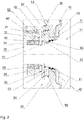
- the bearing housing includes an insert 31 (sealing sleeve) in the area of the shaft seal, which is implemented as a separate component.
- the insert piece 31 is ring-shaped and includes a radially outer oil drainage channel 52 for the splash oil thrown radially outwards from the radial bearing 34 and discharged laterally.
- the insert is sprayed directly or indirectly with spray oil and is thereby actively cooled.
- the spray oil is directed onto the components to be cooled by the oil spray device 61 .
- the oil spray is supplied through the oil duct 60 in the turbine-side bearing flange 62.
- the oil spray device 61 is designed and aligned as a bore in such a way that the oil spray hits the inner contour 63 in the area of the bearing housing 30 and the insert piece in the area of the oil drainage channel 52 wetted.
- the splash oil and the oil from the bearing 34 and oil drain channel 51 cool the insert and the piston rings, seals and drain chambers located therein extensively and coking is largely prevented.
- the insert piece 31 is optionally made from a material with the highest possible thermal conductivity. Furthermore, the components of the shaft seal 31, 30, 41, 42 can be separated from the hot turbine rear wall 11 and wheel rear space 15 by an additional heat plate 70.
- the heat plate 70 is arranged in the area of the wheel rear space 15 between the hot turbine rear wall 11 and the insert 31 of the shaft seal.
- the heat plate rests on the insert piece 31 with a bearing surface 71 in the radially inner area. This heat plate 70 additionally reduces the material temperatures in the area of the insert 31 and the piston rings 41, 42, which in turn minimizes the tendency to form coking.
- the oil drainage channel 52 is delimited in the axial direction by a radially extended sealing plate 32 which in turn is itself cooled by the oil in the drainage channel 51 .
- the insert also includes recesses for receiving two series-arranged piston rings 41 and 42, which are known per se and whose mode of operation is described above in the prior art.
- the insert further comprises an oil drainage chamber 53, a separate gas outlet chamber 55 for gas leakage from the two piston rings 41 and 42 and a sealing web 33 which separates the oil drainage chamber 53 and the gas outlet chamber 55 from one another.
- the oil drainage channel 51 between the radial bearing 34 and the sealing plate 32 forms the first main drainage channel for the bearing oil emerging from the radial bearing.
- the sealing plate 32 forms a first radial web 21 of the shaft 20 with a radially opposite first web Sealing gap 43, due to which penetration of the bearing oil from the oil drainage channel 51 into the oil drainage chamber 53 is minimized.
- the rotating shaft contour of the oil discharge chamber 53 is provided with a discharge groove that is offset radially inward, resulting in two splash edges to the left and right of this groove within the oil discharge chamber 53 .
- the oil thrown through the splash edges into the radially outer region of the oil drain chamber 53 formed by the groove in the insert piece 31 flows downwards within the oil drain chamber 53 along the contour of the insert piece 31 due to gravity. So that the bearing oil can be fed back from the oil drain chamber 53 into the oil circuit for bearing lubrication, the oil drain chamber 53 has at least one oil drain channel 54 in the lower region.
- the insert piece 31 of the shaft seal designed according to the invention is characterized by a gas outlet chamber 55 which is arranged next to the oil drain chamber 53 and is separated from the oil drain chamber 53 by a circumferential sealing web 33 .
- the annular gas outlet chamber 55 is used for collecting the hot gas flowing through the piston rings 41 and 42 .
- the sealing web 33 forms a second radial sealing gap 44 with a radially opposite second web 22 of the shaft 20.
- the sealing gap 44 cleanly separates the two media oil from the oil drain chamber 53 from the gas from the gas outlet chamber 55.
- the gas collected in the gas outlet chamber 55 is in turn transferred through at least one separate gas discharge channel 56 within the insert piece 31 and separately from the oil discharge channel 54 into the common volume of the cavity 50 in the bearing housing.
- the intentional separation of the two drains is intended to prevent the two media from mixing in the area of the oil drain chamber 53, thereby reducing the risk of coking in the sealing compound.
- the major part of the bearing oil escaping from the radial bearing 34 is discharged to the outside through the large oil drainage channel 51 and the first sealing point 43 and is kept away from the piston ring section via the oil drainage channel 52 .
- outlets of the at least one oil drainage channel 54 and of the gas drainage channel 56 are offset in the circumferential direction, as shown in FIG 3 and 4 is shown.
- 3 shows a view from below of the insert 31 without shaft and adjacent housing parts.
- the openings of the two oil drain channels 54 and of the gas drain channel 56, which lead out of the insert at the bottom, are offset axially and in particular in the circumferential direction.
- 4 shows the outflow channels and the radially inwardly protruding sealing plate 32 and in the area of the gas outflow channel 56 the radially inwardly protruding sealing web 33 in the section along IV-IV.
- the offset channel outlets result in greater strength of the insert.
- the seals 43 and 44 are designed as radial sealing gaps.
- these seals can be supplemented or replaced with piston ring seals or other sealing elements.
- the bearing housing can be designed without a separate insert piece in the area of the shaft seal designed according to the invention.
- the corresponding grooves, sealing plates and sealing webs are embedded directly in the bearing housing.
- the embodiment described in detail with a separate insert piece has the advantage that the insert piece can be made of a material with good thermal conductivity (e.g. Ck45) for the purpose of cooling the sealing part and is therefore independent of the bearing housing material used (e.g. GGG -40).
- an insert can be easily replaced in the event of operational wear or can be removed from the bearing housing for a short period of time, for example for cleaning purposes.
- the rotating shaft contour of the turbine in the area of the shaft seal designed according to the invention can be implemented by a sleeve-shaped attachment 81 .
- the attachment 81 is shrunk onto a seat 82 on the shaft and an edge formed on the shaft serves as an axial stop 83 for the attachment.
- the attachment and the shaft seat are to be designed in such a way that the heat dissipation is maximized via the oil cooling and the heat input via the shrink fit on the wave is minimized.
- the attachment is therefore to be made of a material with good thermal conductivity.
- the oil drain channels are also cooled, which in turn minimizes the risk of coking in the drain brackets 53 and 55.
- the attachment 81 can also be fixed to the shaft in a non-positive and/or positive manner in a different way, for example by means of a screw connection (thread) between the attachment and the shaft.
- the shaft seal comprises two piston rings 41 and 42.
- only one piston ring can be provided, or further piston rings can be provided in the area or at other points of the shaft seal.
- the embodiment shown and described in detail shows the shaft seal designed according to the invention on the turbine side of an exhaust gas turbocharger or a power turbine.
- the shaft seal designed according to the invention can also be used analogously on the compressor side of an exhaust gas turbocharger, or in any other turbomachine.
Landscapes
- Engineering & Computer Science (AREA)
- Mechanical Engineering (AREA)
- General Engineering & Computer Science (AREA)
- Chemical & Material Sciences (AREA)
- Combustion & Propulsion (AREA)
- Supercharger (AREA)
- Structures Of Non-Positive Displacement Pumps (AREA)
Claims (13)
- Joint d'étanchéité d'arbre d'un arbre (20) supporté dans un logement de palier (30) d'une turbomachine entre une cavité (50) dans le logement de palier (30) et un espace arrière de rotor (15) d'un rotor (11) de la turbomachine, comprenant un joint d'étanchéité côté rotor (41, 42) entre le logement de palier (30, 31) et l'arbre (20, 21), ainsi qu'un joint d'étanchéité côté palier (43) entre le logement de palier (30, 31) et l'arbre (20, 21), une chambre d'écoulement d'huile (53) étant prévue entre le joint d'étanchéité côté rotor et le joint d'étanchéité côté palier,
caractérisé en ce quela chambre d'écoulement d'huile (53) est limitée par un troisième joint d'étanchéité (44) entre le logement de palier (30, 31) et l'arbre (20, 22), et en ce qu'entre le troisième joint d'étanchéité et le joint d'étanchéité côté rotor est disposée une chambre de sortie de gaz (55), etdans le logement de palier, radialement à l'extérieur de la chambre d'écoulement d'huile (53), est incorporée une rigole d'écoulement d'huile (52), au moins un dispositif de pulvérisation d'huile (61) étant disposé dans la région de la rigole d'écoulement d'huile (52), avec lequel la région de la rigole d'écoulement d'huile peut être pulvérisée avec de l'huile, dans lequel la chambre d'écoulement d'huile (53) et la chambre de sortie de gaz (55) comprennent chacune au moins un canal d'écoulement séparé (54, 56). - Joint d'étanchéité d'arbre selon la revendication 1, dans lequel le joint d'étanchéité côté rotor est réalisé sous la forme d'au moins un segment de piston (41, 42).
- Joint d'étanchéité d'arbre selon l'une quelconque des revendications 1 ou 2, dans lequel le joint d'étanchéité côté palier est réalisé sous la forme d'une fente d'étanchéité (43).
- Joint d'étanchéité d'arbre selon l'une quelconque des revendications 1 à 3, dans lequel le troisième joint d'étanchéité est réalisé sous la forme d'une fente d'étanchéité (44).
- Joint d'étanchéité d'arbre selon les revendications 1 à 4, dans lequel, à l'intérieur de l'espace arrière de rotor (15), un bouclier thermique (70) protège le joint d'étanchéité d'arbre de la paroi arrière chaude (11) de la turbine.
- Joint d'étanchéité d'arbre selon l'une quelconque des revendications 1 à 5, dans lequel le logement de palier, dans la région du joint d'étanchéité d'arbre, comprend une pièce d'insertion (31), dans laquelle sont réalisés des évidements qui forment la chambre d'écoulement d'huile (53) ainsi que la chambre de sortie de gaz (55).
- Joint d'étanchéité d'arbre selon l'une quelconque des revendications 1 à 6, dans lequel l'au moins un canal d'écoulement (54) de la chambre d'écoulement d'huile (53) et l'au moins un canal d'écoulement (56) de la chambre de sortie de gaz (55) débouchent séparément l'un de l'autre dans la cavité (50) dans le logement de palier (30).
- Joint d'étanchéité d'arbre selon la revendication 7, dans lequel l'au moins un canal d'écoulement (54) de la chambre d'écoulement d'huile (53) et l'au moins un canal d'écoulement (56) de la chambre de sortie de gaz (55) débouchent de manière décalée dans la direction périphérique dans la cavité (50) dans le logement de palier (30).
- Joint d'étanchéité d'arbre selon l'une quelconque des revendications 1 à 8, dans lequel l'arbre comprend, dans la région du joint d'étanchéité d'arbre, une coiffe (81) qui présente un contour qui forme, conjointement avec le logement de palier, la chambre d'écoulement d'huile (53) ainsi que la chambre de sortie de gaz (55).
- Joint d'étanchéité d'arbre selon la revendication 9, dans lequel la coiffe (81) est fabriquée en un matériau qui présente, par rapport au matériau de l'arbre, une plus grande conductibilité thermique.
- Turbomachine, comprenant au moins un rotor (11) disposé sur un arbre (20) ainsi qu'un logement de palier (30), dans lequel l'arbre (20) est supporté de manière rotative, un joint d'étanchéité d'arbre selon l'une quelconque des revendications 1 à 9 étant disposé entre le logement de palier (30) et l'arbre (20).
- Turbocompresseur à gaz d'échappement ou turbine de puissance, comprenant au moins un rotor de turbine (11) disposé sur un arbre (20) ainsi qu'un logement de palier (30) dans lequel l'arbre (20) est supporté de manière rotative, un joint d'étanchéité d'arbre selon l'une quelconque des revendications 1 à 9 étant disposé entre le logement de palier (30) et l'arbre (20).
- Turbocompresseur à gaz d'échappement comprenant au moins un rotor de compresseur (11) disposé sur un arbre (20), ainsi qu'un logement de palier (30) dans lequel l'arbre (20) est supporté de manière rotative, un joint d'étanchéité d'arbre selon l'une quelconque des revendications 1 à 9 étant disposé entre le logement de palier (30) et l'arbre (20).
Applications Claiming Priority (1)
| Application Number | Priority Date | Filing Date | Title |
|---|---|---|---|
| DE102010003796A DE102010003796A1 (de) | 2010-04-09 | 2010-04-09 | Wellenabdichtung |
Publications (4)
| Publication Number | Publication Date |
|---|---|
| EP2375000A2 EP2375000A2 (fr) | 2011-10-12 |
| EP2375000A3 EP2375000A3 (fr) | 2017-06-28 |
| EP2375000B1 EP2375000B1 (fr) | 2019-01-16 |
| EP2375000B2 true EP2375000B2 (fr) | 2022-12-14 |
Family
ID=43824234
Family Applications (1)
| Application Number | Title | Priority Date | Filing Date |
|---|---|---|---|
| EP11159510.4A Active EP2375000B2 (fr) | 2010-04-09 | 2011-03-24 | Joint d'arbre |
Country Status (6)
| Country | Link |
|---|---|
| US (1) | US9169738B2 (fr) |
| EP (1) | EP2375000B2 (fr) |
| JP (1) | JP5259768B2 (fr) |
| KR (1) | KR101433817B1 (fr) |
| CN (1) | CN102213117B (fr) |
| DE (1) | DE102010003796A1 (fr) |
Families Citing this family (23)
| Publication number | Priority date | Publication date | Assignee | Title |
|---|---|---|---|---|
| EP2218998B1 (fr) * | 2009-02-03 | 2012-12-19 | Ipsen, Inc. | Mécanisme d'étanchéité pour four de traitement à la chaleur sous vide |
| GB201220300D0 (en) | 2012-11-12 | 2012-12-26 | Cummins Ltd | Turbomachine bearing assembly preloading arrangement |
| KR101536061B1 (ko) * | 2012-12-14 | 2015-07-10 | 에이비비 터보 시스템즈 아게 | 샤프트 시일 |
| CN103133064A (zh) * | 2013-03-15 | 2013-06-05 | 联优机械(常熟)有限公司 | 具有自密封功能的透平膨胀机外功输出连接装置的连接轴结构 |
| DE102013213023A1 (de) * | 2013-07-03 | 2015-01-08 | Continental Automotive Gmbh | Läufer für eine Turboladereinrichtung, Turboladereinrichtung mit einem Läufer und Welle für einen solchen Läufer |
| DE102014011849A1 (de) * | 2014-08-08 | 2016-02-11 | Man Diesel & Turbo Se | Wellendichtungssystem und Abgasturbolader |
| US9995161B2 (en) * | 2014-11-12 | 2018-06-12 | Borgwarner Inc. | Modular turbocharger clearance seal |
| US9732633B2 (en) * | 2015-03-09 | 2017-08-15 | Caterpillar Inc. | Turbocharger turbine assembly |
| JP2016188672A (ja) * | 2015-03-30 | 2016-11-04 | 日野自動車株式会社 | シールリング |
| US9638203B2 (en) * | 2015-09-15 | 2017-05-02 | Borgwarner Inc. | Bearing housing |
| DE102017202687A1 (de) | 2017-02-20 | 2018-08-23 | BMTS Technology GmbH & Co. KG | Lagergehäuse und ein Abgasturoblader mit einem solchen Gehäuse |
| US10669873B2 (en) * | 2017-04-06 | 2020-06-02 | Raytheon Technologies Corporation | Insulated seal seat |
| DE112018004553T5 (de) * | 2017-10-16 | 2020-05-28 | Ihi Corporation | Abdichtaufbau für einen Turbolader |
| US10837447B2 (en) * | 2017-10-30 | 2020-11-17 | Ulvac, Inc. | Vacuum pump having a first housing with a supply port and a second housing with a recess portion |
| CN109026179A (zh) * | 2018-08-02 | 2018-12-18 | 嘉兴博瑞涡轮增压技术有限公司 | 一种新型增压器密封结构 |
| CN108952848A (zh) * | 2018-08-02 | 2018-12-07 | 嘉兴博瑞涡轮增压技术有限公司 | 一种高效涡轮增压器壳体结构 |
| US10746099B1 (en) * | 2019-04-03 | 2020-08-18 | GM Global Technology Operations LLC | Multi-step bore turbocharger |
| US11371521B2 (en) * | 2019-04-10 | 2022-06-28 | Borgwarner Inc. | High temperature face seal |
| US11655721B2 (en) | 2020-10-29 | 2023-05-23 | Borgwarner Inc. | Turbocharger including a sealing assembly |
| CN113623029A (zh) * | 2021-09-18 | 2021-11-09 | 中车大连机车研究所有限公司 | 一种涡轮增压器轴承转子密封结构 |
| CN115387860B (zh) * | 2022-08-18 | 2025-05-16 | 中车大连机车研究所有限公司 | 一种涡轮增压器涡轮端油气密封结构 |
| WO2025252828A1 (fr) | 2024-06-05 | 2025-12-11 | Accelleron Switzerland Ltd. | Agencement d'étanchéité, turbomachine et procédé de fonctionnement d'une turbomachine |
| WO2025252832A1 (fr) | 2024-06-05 | 2025-12-11 | Accelleron Switzerland Ltd. | Système d'étanchéité pour turbomachine, turbomachine et procédé de fonctionnement d'une turbomachine |
Citations (4)
| Publication number | Priority date | Publication date | Assignee | Title |
|---|---|---|---|---|
| US4268229A (en) † | 1979-04-19 | 1981-05-19 | The Garrett Corporation | Turbocharger shaft seal arrangement |
| US4389052A (en) † | 1979-07-10 | 1983-06-21 | Ishikawajima-Harima Jukogyo Kabushiki Kaisha | Oil seal system for shaft of turbocharger |
| US5890881A (en) † | 1996-11-27 | 1999-04-06 | Alliedsignal Inc. | Pressure balanced turbocharger rotating seal |
| WO2010112864A2 (fr) † | 2009-04-02 | 2010-10-07 | Cummins Turbo Technologies Limited | Machine rotative avec agencement d'étanchéité d'arbre |
Family Cites Families (26)
| Publication number | Priority date | Publication date | Assignee | Title |
|---|---|---|---|---|
| US2709567A (en) * | 1948-12-27 | 1955-05-31 | Garrett Corp | Turbine rotor bearing with cooling and lubricating means |
| GB1045973A (en) | 1962-07-14 | 1966-10-19 | Walter Eberspacher | Exhaust turbo supercharger |
| US3565497A (en) | 1969-05-23 | 1971-02-23 | Caterpillar Tractor Co | Turbocharger seal assembly |
| US3778194A (en) * | 1972-08-28 | 1973-12-11 | Carrier Corp | Turbocharger structure |
| DE2735034C2 (de) | 1976-08-19 | 1981-09-24 | Kabushiki Kaisha Komatsu Seisakusho, Tokyo | Abgasturbolader |
| US4196910A (en) | 1977-05-19 | 1980-04-08 | Ishikawajima-Harima Jukogyo Kabushiki Kaisha | Shaft sealing device for turbocharger |
| JPS5851027A (ja) | 1981-09-16 | 1983-03-25 | Nitto Seiko Co Ltd | ファスナ−部品の抜き取り装置 |
| JPS5851027U (ja) * | 1981-10-05 | 1983-04-06 | 株式会社日立製作所 | タ−ボ過給機の冷却装置 |
| DE3219127C2 (de) * | 1982-05-21 | 1984-04-05 | Mtu Motoren- Und Turbinen-Union Friedrichshafen Gmbh, 7990 Friedrichshafen | Dichtungsvorrichtung für Strömungsmaschinen |
| US4477223A (en) * | 1982-06-11 | 1984-10-16 | Texas Turbine, Inc. | Sealing system for a turboexpander compressor |
| JPS6014246U (ja) * | 1983-07-08 | 1985-01-30 | トヨタ自動車株式会社 | タ−ボチヤ−ジヤのオイル洩れ防止装置 |
| JPS61202649A (ja) | 1985-03-07 | 1986-09-08 | マルハ株式会社 | 魚体の供給位置決め装置 |
| JPS61202649U (fr) * | 1985-06-10 | 1986-12-19 | ||
| DE3737932A1 (de) * | 1987-11-07 | 1989-05-18 | Mtu Friedrichshafen Gmbh | Dichtungsvorrichtung zwischen welle und gehaeuse einer stroemungsmaschine |
| GB9222133D0 (en) * | 1992-10-21 | 1992-12-02 | Leavesley Malcolm G | Turbocharger apparatus |
| DE4330380A1 (de) * | 1993-09-08 | 1995-03-09 | Abb Management Ag | Abgasturbolader mit mehrteiligem Lagergehäuse |
| JPH09264151A (ja) * | 1996-03-29 | 1997-10-07 | Aisin Seiki Co Ltd | ターボチャージャのオイル漏れ防止機構 |
| JP2003511618A (ja) * | 1999-10-12 | 2003-03-25 | エーエルエム ディベロップメント インコーポレイテッド | ターボ形機械の軸受用潤滑システム |
| CN2517874Y (zh) * | 2002-01-18 | 2002-10-23 | 陈浩 | 车用涡轮增压器 |
| EP1394365B1 (fr) * | 2002-09-02 | 2006-10-25 | BorgWarner Inc. | Système d'étanchéité d'arbre pour turbosoufflante |
| AU2003201061A1 (en) | 2003-01-10 | 2004-08-10 | Honeywell International Inc. | Sealing means for a lubrication system in a turbocharger |
| DE102004055429B3 (de) * | 2004-11-17 | 2006-08-10 | Man B & W Diesel Ag | Dichtungseinrichtung für eine insbesondere im Stillstand geschmierte Lagerung einer Rotorwelle |
| JP2009524773A (ja) * | 2006-01-27 | 2009-07-02 | ボーグワーナー・インコーポレーテッド | ウェーブスプリングを用いたvtg機構組立体 |
| US7544039B1 (en) * | 2006-06-14 | 2009-06-09 | Florida Turbine Technologies, Inc. | Dual spool shaft with intershaft seal |
| US8167534B2 (en) * | 2006-09-14 | 2012-05-01 | Solar Turbines Inc. | Seal for a turbine engine |
| CN201330623Y (zh) * | 2008-12-15 | 2009-10-21 | 张焕元 | 汽轮发电机组轴承可调接触式密封装置 |
-
2010
- 2010-04-09 DE DE102010003796A patent/DE102010003796A1/de active Pending
-
2011
- 2011-03-24 EP EP11159510.4A patent/EP2375000B2/fr active Active
- 2011-04-01 KR KR1020110030379A patent/KR101433817B1/ko active Active
- 2011-04-07 US US13/081,897 patent/US9169738B2/en active Active
- 2011-04-08 CN CN201110093627.2A patent/CN102213117B/zh active Active
- 2011-04-11 JP JP2011087016A patent/JP5259768B2/ja active Active
Patent Citations (4)
| Publication number | Priority date | Publication date | Assignee | Title |
|---|---|---|---|---|
| US4268229A (en) † | 1979-04-19 | 1981-05-19 | The Garrett Corporation | Turbocharger shaft seal arrangement |
| US4389052A (en) † | 1979-07-10 | 1983-06-21 | Ishikawajima-Harima Jukogyo Kabushiki Kaisha | Oil seal system for shaft of turbocharger |
| US5890881A (en) † | 1996-11-27 | 1999-04-06 | Alliedsignal Inc. | Pressure balanced turbocharger rotating seal |
| WO2010112864A2 (fr) † | 2009-04-02 | 2010-10-07 | Cummins Turbo Technologies Limited | Machine rotative avec agencement d'étanchéité d'arbre |
Also Published As
| Publication number | Publication date |
|---|---|
| JP5259768B2 (ja) | 2013-08-07 |
| US20110250067A1 (en) | 2011-10-13 |
| EP2375000B1 (fr) | 2019-01-16 |
| EP2375000A3 (fr) | 2017-06-28 |
| KR101433817B1 (ko) | 2014-08-27 |
| CN102213117B (zh) | 2014-08-27 |
| JP2011220338A (ja) | 2011-11-04 |
| KR20110113569A (ko) | 2011-10-17 |
| CN102213117A (zh) | 2011-10-12 |
| US9169738B2 (en) | 2015-10-27 |
| EP2375000A2 (fr) | 2011-10-12 |
| DE102010003796A1 (de) | 2011-10-13 |
Similar Documents
| Publication | Publication Date | Title |
|---|---|---|
| EP2375000B2 (fr) | Joint d'arbre | |
| EP2192272B1 (fr) | Dispositif pour étanchéifier un boîtier de palier de turbocompresseur | |
| DE69502100T2 (de) | Ringförmiges lagergehäuse | |
| DE69721036T2 (de) | Druckausgeglichene drehdichtung für turbolader | |
| EP2071131B1 (fr) | Etanchéification d'au moins un arbre à l'aide d'au moins un joint hydraulique | |
| DE102008044415A1 (de) | Verfahren und Systeme zur Abdichtung rotierender Maschinen | |
| EP2743460B1 (fr) | Système d'étanchéité d'arbre | |
| EP3267089A1 (fr) | Système de distribution d'huile et turbomachine le comprenant | |
| EP3392471A2 (fr) | Logement de palier et compresseur turbo avec un logement de palier | |
| DE102016002719A1 (de) | Turbolader und Verfahren | |
| EP2112332B1 (fr) | Anneau support de distributeur avec canal pressurisé | |
| WO2001016467A1 (fr) | Turbine et procede pour evacuer du fluide de fuite | |
| EP2730744B1 (fr) | Turbosoufflante de gaz d'échappement | |
| EP2054629B1 (fr) | Système d'étanchéité d'arbre | |
| EP0690204A2 (fr) | Turbine à vapeur ayant au moins deux joint pour assurer l'étanchéité du carter | |
| EP3374602B1 (fr) | Agencement d'étanchement d'un carter de palier et turbocompresseur ayant un tel agencement | |
| CH703516B1 (de) | Turbomaschine. | |
| CH703204B1 (de) | Turbomaschine. | |
| DE102012011144A1 (de) | Hydraulische Dichtungsanordnung | |
| EP2792855B1 (fr) | Support de palier interieur d'un turbocompresseur | |
| CH703515B1 (de) | Turbomaschine. | |
| CH714388B1 (de) | Turbolader. | |
| EP3371420B1 (fr) | Agencement pour séparation des écoulements d'huile lubrifiante et turbocompresseur ayant un tel agencement | |
| WO2008106931A1 (fr) | Élément d'étanchéité pour fermer hermétiquement un interstice entre le stator et le rotor d'une turbomachine axiale | |
| WO2021110191A1 (fr) | Support d'étanchéité conçu pour une turbomachine comportant des ouvertures de type fentes dans le corps d'étanchéité |
Legal Events
| Date | Code | Title | Description |
|---|---|---|---|
| PUAI | Public reference made under article 153(3) epc to a published international application that has entered the european phase |
Free format text: ORIGINAL CODE: 0009012 |
|
| AK | Designated contracting states |
Kind code of ref document: A2 Designated state(s): AL AT BE BG CH CY CZ DE DK EE ES FI FR GB GR HR HU IE IS IT LI LT LU LV MC MK MT NL NO PL PT RO RS SE SI SK SM TR |
|
| AX | Request for extension of the european patent |
Extension state: BA ME |
|
| PUAL | Search report despatched |
Free format text: ORIGINAL CODE: 0009013 |
|
| AK | Designated contracting states |
Kind code of ref document: A3 Designated state(s): AL AT BE BG CH CY CZ DE DK EE ES FI FR GB GR HR HU IE IS IT LI LT LU LV MC MK MT NL NO PL PT RO RS SE SI SK SM TR |
|
| AX | Request for extension of the european patent |
Extension state: BA ME |
|
| RIC1 | Information provided on ipc code assigned before grant |
Ipc: F01D 25/12 20060101ALI20170522BHEP Ipc: F01D 25/18 20060101ALI20170522BHEP Ipc: F01D 11/00 20060101AFI20170522BHEP |
|
| STAA | Information on the status of an ep patent application or granted ep patent |
Free format text: STATUS: REQUEST FOR EXAMINATION WAS MADE |
|
| 17P | Request for examination filed |
Effective date: 20171221 |
|
| RBV | Designated contracting states (corrected) |
Designated state(s): AL AT BE BG CH CY CZ DE DK EE ES FI FR GB GR HR HU IE IS IT LI LT LU LV MC MK MT NL NO PL PT RO RS SE SI SK SM TR |
|
| GRAP | Despatch of communication of intention to grant a patent |
Free format text: ORIGINAL CODE: EPIDOSNIGR1 |
|
| STAA | Information on the status of an ep patent application or granted ep patent |
Free format text: STATUS: GRANT OF PATENT IS INTENDED |
|
| INTG | Intention to grant announced |
Effective date: 20180627 |
|
| GRAS | Grant fee paid |
Free format text: ORIGINAL CODE: EPIDOSNIGR3 |
|
| GRAA | (expected) grant |
Free format text: ORIGINAL CODE: 0009210 |
|
| STAA | Information on the status of an ep patent application or granted ep patent |
Free format text: STATUS: THE PATENT HAS BEEN GRANTED |
|
| AK | Designated contracting states |
Kind code of ref document: B1 Designated state(s): AL AT BE BG CH CY CZ DE DK EE ES FI FR GB GR HR HU IE IS IT LI LT LU LV MC MK MT NL NO PL PT RO RS SE SI SK SM TR |
|
| REG | Reference to a national code |
Ref country code: GB Ref legal event code: FG4D Free format text: NOT ENGLISH |
|
| REG | Reference to a national code |
Ref country code: CH Ref legal event code: EP |
|
| REG | Reference to a national code |
Ref country code: IE Ref legal event code: FG4D Free format text: LANGUAGE OF EP DOCUMENT: GERMAN |
|
| REG | Reference to a national code |
Ref country code: DE Ref legal event code: R096 Ref document number: 502011015283 Country of ref document: DE |
|
| REG | Reference to a national code |
Ref country code: AT Ref legal event code: REF Ref document number: 1089844 Country of ref document: AT Kind code of ref document: T Effective date: 20190215 |
|
| REG | Reference to a national code |
Ref country code: NL Ref legal event code: MP Effective date: 20190116 |
|
| REG | Reference to a national code |
Ref country code: LT Ref legal event code: MG4D |
|
| PG25 | Lapsed in a contracting state [announced via postgrant information from national office to epo] |
Ref country code: NL Free format text: LAPSE BECAUSE OF FAILURE TO SUBMIT A TRANSLATION OF THE DESCRIPTION OR TO PAY THE FEE WITHIN THE PRESCRIBED TIME-LIMIT Effective date: 20190116 |
|
| PG25 | Lapsed in a contracting state [announced via postgrant information from national office to epo] |
Ref country code: ES Free format text: LAPSE BECAUSE OF FAILURE TO SUBMIT A TRANSLATION OF THE DESCRIPTION OR TO PAY THE FEE WITHIN THE PRESCRIBED TIME-LIMIT Effective date: 20190116 Ref country code: PT Free format text: LAPSE BECAUSE OF FAILURE TO SUBMIT A TRANSLATION OF THE DESCRIPTION OR TO PAY THE FEE WITHIN THE PRESCRIBED TIME-LIMIT Effective date: 20190516 Ref country code: LT Free format text: LAPSE BECAUSE OF FAILURE TO SUBMIT A TRANSLATION OF THE DESCRIPTION OR TO PAY THE FEE WITHIN THE PRESCRIBED TIME-LIMIT Effective date: 20190116 Ref country code: FI Free format text: LAPSE BECAUSE OF FAILURE TO SUBMIT A TRANSLATION OF THE DESCRIPTION OR TO PAY THE FEE WITHIN THE PRESCRIBED TIME-LIMIT Effective date: 20190116 Ref country code: NO Free format text: LAPSE BECAUSE OF FAILURE TO SUBMIT A TRANSLATION OF THE DESCRIPTION OR TO PAY THE FEE WITHIN THE PRESCRIBED TIME-LIMIT Effective date: 20190416 Ref country code: PL Free format text: LAPSE BECAUSE OF FAILURE TO SUBMIT A TRANSLATION OF THE DESCRIPTION OR TO PAY THE FEE WITHIN THE PRESCRIBED TIME-LIMIT Effective date: 20190116 Ref country code: SE Free format text: LAPSE BECAUSE OF FAILURE TO SUBMIT A TRANSLATION OF THE DESCRIPTION OR TO PAY THE FEE WITHIN THE PRESCRIBED TIME-LIMIT Effective date: 20190116 |
|
| PG25 | Lapsed in a contracting state [announced via postgrant information from national office to epo] |
Ref country code: BG Free format text: LAPSE BECAUSE OF FAILURE TO SUBMIT A TRANSLATION OF THE DESCRIPTION OR TO PAY THE FEE WITHIN THE PRESCRIBED TIME-LIMIT Effective date: 20190416 Ref country code: IS Free format text: LAPSE BECAUSE OF FAILURE TO SUBMIT A TRANSLATION OF THE DESCRIPTION OR TO PAY THE FEE WITHIN THE PRESCRIBED TIME-LIMIT Effective date: 20190516 Ref country code: GR Free format text: LAPSE BECAUSE OF FAILURE TO SUBMIT A TRANSLATION OF THE DESCRIPTION OR TO PAY THE FEE WITHIN THE PRESCRIBED TIME-LIMIT Effective date: 20190417 Ref country code: RS Free format text: LAPSE BECAUSE OF FAILURE TO SUBMIT A TRANSLATION OF THE DESCRIPTION OR TO PAY THE FEE WITHIN THE PRESCRIBED TIME-LIMIT Effective date: 20190116 Ref country code: LV Free format text: LAPSE BECAUSE OF FAILURE TO SUBMIT A TRANSLATION OF THE DESCRIPTION OR TO PAY THE FEE WITHIN THE PRESCRIBED TIME-LIMIT Effective date: 20190116 Ref country code: HR Free format text: LAPSE BECAUSE OF FAILURE TO SUBMIT A TRANSLATION OF THE DESCRIPTION OR TO PAY THE FEE WITHIN THE PRESCRIBED TIME-LIMIT Effective date: 20190116 |
|
| REG | Reference to a national code |
Ref country code: DE Ref legal event code: R026 Ref document number: 502011015283 Country of ref document: DE |
|
| PLBI | Opposition filed |
Free format text: ORIGINAL CODE: 0009260 |
|
| PLAX | Notice of opposition and request to file observation + time limit sent |
Free format text: ORIGINAL CODE: EPIDOSNOBS2 |
|
| PG25 | Lapsed in a contracting state [announced via postgrant information from national office to epo] |
Ref country code: SK Free format text: LAPSE BECAUSE OF FAILURE TO SUBMIT A TRANSLATION OF THE DESCRIPTION OR TO PAY THE FEE WITHIN THE PRESCRIBED TIME-LIMIT Effective date: 20190116 Ref country code: RO Free format text: LAPSE BECAUSE OF FAILURE TO SUBMIT A TRANSLATION OF THE DESCRIPTION OR TO PAY THE FEE WITHIN THE PRESCRIBED TIME-LIMIT Effective date: 20190116 Ref country code: AL Free format text: LAPSE BECAUSE OF FAILURE TO SUBMIT A TRANSLATION OF THE DESCRIPTION OR TO PAY THE FEE WITHIN THE PRESCRIBED TIME-LIMIT Effective date: 20190116 Ref country code: MC Free format text: LAPSE BECAUSE OF FAILURE TO SUBMIT A TRANSLATION OF THE DESCRIPTION OR TO PAY THE FEE WITHIN THE PRESCRIBED TIME-LIMIT Effective date: 20190116 Ref country code: DK Free format text: LAPSE BECAUSE OF FAILURE TO SUBMIT A TRANSLATION OF THE DESCRIPTION OR TO PAY THE FEE WITHIN THE PRESCRIBED TIME-LIMIT Effective date: 20190116 Ref country code: EE Free format text: LAPSE BECAUSE OF FAILURE TO SUBMIT A TRANSLATION OF THE DESCRIPTION OR TO PAY THE FEE WITHIN THE PRESCRIBED TIME-LIMIT Effective date: 20190116 Ref country code: IT Free format text: LAPSE BECAUSE OF FAILURE TO SUBMIT A TRANSLATION OF THE DESCRIPTION OR TO PAY THE FEE WITHIN THE PRESCRIBED TIME-LIMIT Effective date: 20190116 |
|
| REG | Reference to a national code |
Ref country code: CH Ref legal event code: PL |
|
| 26 | Opposition filed |
Opponent name: MAN ENERGY SOLUTIONS SE Effective date: 20191014 |
|
| PG25 | Lapsed in a contracting state [announced via postgrant information from national office to epo] |
Ref country code: LU Free format text: LAPSE BECAUSE OF NON-PAYMENT OF DUE FEES Effective date: 20190324 Ref country code: SM Free format text: LAPSE BECAUSE OF FAILURE TO SUBMIT A TRANSLATION OF THE DESCRIPTION OR TO PAY THE FEE WITHIN THE PRESCRIBED TIME-LIMIT Effective date: 20190116 |
|
| REG | Reference to a national code |
Ref country code: BE Ref legal event code: MM Effective date: 20190331 |
|
| PG25 | Lapsed in a contracting state [announced via postgrant information from national office to epo] |
Ref country code: CH Free format text: LAPSE BECAUSE OF NON-PAYMENT OF DUE FEES Effective date: 20190331 Ref country code: LI Free format text: LAPSE BECAUSE OF NON-PAYMENT OF DUE FEES Effective date: 20190331 Ref country code: IE Free format text: LAPSE BECAUSE OF NON-PAYMENT OF DUE FEES Effective date: 20190324 |
|
| PG25 | Lapsed in a contracting state [announced via postgrant information from national office to epo] |
Ref country code: SI Free format text: LAPSE BECAUSE OF FAILURE TO SUBMIT A TRANSLATION OF THE DESCRIPTION OR TO PAY THE FEE WITHIN THE PRESCRIBED TIME-LIMIT Effective date: 20190116 Ref country code: FR Free format text: LAPSE BECAUSE OF NON-PAYMENT OF DUE FEES Effective date: 20190331 Ref country code: BE Free format text: LAPSE BECAUSE OF NON-PAYMENT OF DUE FEES Effective date: 20190331 |
|
| PLBB | Reply of patent proprietor to notice(s) of opposition received |
Free format text: ORIGINAL CODE: EPIDOSNOBS3 |
|
| PG25 | Lapsed in a contracting state [announced via postgrant information from national office to epo] |
Ref country code: TR Free format text: LAPSE BECAUSE OF FAILURE TO SUBMIT A TRANSLATION OF THE DESCRIPTION OR TO PAY THE FEE WITHIN THE PRESCRIBED TIME-LIMIT Effective date: 20190116 |
|
| PG25 | Lapsed in a contracting state [announced via postgrant information from national office to epo] |
Ref country code: MT Free format text: LAPSE BECAUSE OF FAILURE TO SUBMIT A TRANSLATION OF THE DESCRIPTION OR TO PAY THE FEE WITHIN THE PRESCRIBED TIME-LIMIT Effective date: 20190116 |
|
| RAP2 | Party data changed (patent owner data changed or rights of a patent transferred) |
Owner name: ABB SCHWEIZ AG |
|
| REG | Reference to a national code |
Ref country code: DE Ref legal event code: R081 Ref document number: 502011015283 Country of ref document: DE Owner name: TURBO SYSTEMS SWITZERLAND LTD., CH Free format text: FORMER OWNER: ABB TURBO SYSTEMS AG, BADEN, CH Ref country code: DE Ref legal event code: R082 Ref document number: 502011015283 Country of ref document: DE Representative=s name: ZIMMERMANN & PARTNER PATENTANWAELTE MBB, DE Ref country code: DE Ref legal event code: R081 Ref document number: 502011015283 Country of ref document: DE Owner name: ABB SCHWEIZ AG, CH Free format text: FORMER OWNER: ABB TURBO SYSTEMS AG, BADEN, CH |
|
| RAP2 | Party data changed (patent owner data changed or rights of a patent transferred) |
Owner name: ABB SCHWEIZ AG |
|
| REG | Reference to a national code |
Ref country code: GB Ref legal event code: 732E Free format text: REGISTERED BETWEEN 20210225 AND 20210303 |
|
| REG | Reference to a national code |
Ref country code: GB Ref legal event code: 732E Free format text: REGISTERED BETWEEN 20210304 AND 20210310 |
|
| REG | Reference to a national code |
Ref country code: AT Ref legal event code: PC Ref document number: 1089844 Country of ref document: AT Kind code of ref document: T Owner name: ABB SCHWEIZ AG, CH Effective date: 20210217 |
|
| PG25 | Lapsed in a contracting state [announced via postgrant information from national office to epo] |
Ref country code: CY Free format text: LAPSE BECAUSE OF FAILURE TO SUBMIT A TRANSLATION OF THE DESCRIPTION OR TO PAY THE FEE WITHIN THE PRESCRIBED TIME-LIMIT Effective date: 20190116 |
|
| PG25 | Lapsed in a contracting state [announced via postgrant information from national office to epo] |
Ref country code: HU Free format text: LAPSE BECAUSE OF FAILURE TO SUBMIT A TRANSLATION OF THE DESCRIPTION OR TO PAY THE FEE WITHIN THE PRESCRIBED TIME-LIMIT; INVALID AB INITIO Effective date: 20110324 |
|
| RAP2 | Party data changed (patent owner data changed or rights of a patent transferred) |
Owner name: TURBO SYSTEMS SWITZERLAND LTD. |
|
| PG25 | Lapsed in a contracting state [announced via postgrant information from national office to epo] |
Ref country code: MK Free format text: LAPSE BECAUSE OF FAILURE TO SUBMIT A TRANSLATION OF THE DESCRIPTION OR TO PAY THE FEE WITHIN THE PRESCRIBED TIME-LIMIT Effective date: 20190116 |
|
| REG | Reference to a national code |
Ref country code: GB Ref legal event code: 732E Free format text: REGISTERED BETWEEN 20220922 AND 20220928 |
|
| REG | Reference to a national code |
Ref country code: DE Ref legal event code: R081 Ref document number: 502011015283 Country of ref document: DE Owner name: TURBO SYSTEMS SWITZERLAND LTD., CH Free format text: FORMER OWNER: ABB SCHWEIZ AG, BADEN, CH Ref country code: DE Ref legal event code: R081 Ref document number: 502011015283 Country of ref document: DE Owner name: ACCELLERON SWITZERLAND LTD., CH Free format text: FORMER OWNER: ABB SCHWEIZ AG, BADEN, CH |
|
| PUAH | Patent maintained in amended form |
Free format text: ORIGINAL CODE: 0009272 |
|
| STAA | Information on the status of an ep patent application or granted ep patent |
Free format text: STATUS: PATENT MAINTAINED AS AMENDED |
|
| 27A | Patent maintained in amended form |
Effective date: 20221214 |
|
| AK | Designated contracting states |
Kind code of ref document: B2 Designated state(s): AL AT BE BG CH CY CZ DE DK EE ES FI FR GB GR HR HU IE IS IT LI LT LU LV MC MK MT NL NO PL PT RO RS SE SI SK SM TR |
|
| REG | Reference to a national code |
Ref country code: DE Ref legal event code: R102 Ref document number: 502011015283 Country of ref document: DE |
|
| REG | Reference to a national code |
Ref country code: AT Ref legal event code: PC Ref document number: 1089844 Country of ref document: AT Kind code of ref document: T Owner name: TURBO SYSTEMS SWITZERLAND LTD, CH Effective date: 20230320 |
|
| PGFP | Annual fee paid to national office [announced via postgrant information from national office to epo] |
Ref country code: CZ Payment date: 20250318 Year of fee payment: 15 |
|
| REG | Reference to a national code |
Ref country code: DE Ref legal event code: R081 Ref document number: 502011015283 Country of ref document: DE Owner name: ACCELLERON SWITZERLAND LTD., CH Free format text: FORMER OWNER: TURBO SYSTEMS SWITZERLAND LTD., BADEN, CH |
|
| REG | Reference to a national code |
Ref country code: AT Ref legal event code: HC Ref document number: 1089844 Country of ref document: AT Kind code of ref document: T Owner name: ACCELLERON SWITZERLAND LTD., CH Effective date: 20250729 |
|
| PGFP | Annual fee paid to national office [announced via postgrant information from national office to epo] |
Ref country code: GB Payment date: 20260324 Year of fee payment: 16 |
|
| PGFP | Annual fee paid to national office [announced via postgrant information from national office to epo] |
Ref country code: DE Payment date: 20260319 Year of fee payment: 16 |
|
| PGFP | Annual fee paid to national office [announced via postgrant information from national office to epo] |
Ref country code: AT Payment date: 20260320 Year of fee payment: 16 |