EP2375181A1 - Ventilateur avec un echangeur de chaleur à contre courant - Google Patents
Ventilateur avec un echangeur de chaleur à contre courant Download PDFInfo
- Publication number
- EP2375181A1 EP2375181A1 EP11162145A EP11162145A EP2375181A1 EP 2375181 A1 EP2375181 A1 EP 2375181A1 EP 11162145 A EP11162145 A EP 11162145A EP 11162145 A EP11162145 A EP 11162145A EP 2375181 A1 EP2375181 A1 EP 2375181A1
- Authority
- EP
- European Patent Office
- Prior art keywords
- air
- ventilator
- paths
- inlet
- ventilator according
- Prior art date
- Legal status (The legal status is an assumption and is not a legal conclusion. Google has not performed a legal analysis and makes no representation as to the accuracy of the status listed.)
- Withdrawn
Links
Images
Classifications
-
- F—MECHANICAL ENGINEERING; LIGHTING; HEATING; WEAPONS; BLASTING
- F24—HEATING; RANGES; VENTILATING
- F24F—AIR-CONDITIONING; AIR-HUMIDIFICATION; VENTILATION; USE OF AIR CURRENTS FOR SCREENING
- F24F12/00—Use of energy recovery systems in air conditioning, ventilation or screening
- F24F12/001—Use of energy recovery systems in air conditioning, ventilation or screening with heat-exchange between supplied and exhausted air
- F24F12/006—Use of energy recovery systems in air conditioning, ventilation or screening with heat-exchange between supplied and exhausted air using an air-to-air heat exchanger
-
- F—MECHANICAL ENGINEERING; LIGHTING; HEATING; WEAPONS; BLASTING
- F24—HEATING; RANGES; VENTILATING
- F24F—AIR-CONDITIONING; AIR-HUMIDIFICATION; VENTILATION; USE OF AIR CURRENTS FOR SCREENING
- F24F13/00—Details common to, or for air-conditioning, air-humidification, ventilation or use of air currents for screening
- F24F13/30—Arrangement or mounting of heat-exchangers
-
- F—MECHANICAL ENGINEERING; LIGHTING; HEATING; WEAPONS; BLASTING
- F28—HEAT EXCHANGE IN GENERAL
- F28D—HEAT-EXCHANGE APPARATUS, NOT PROVIDED FOR IN ANOTHER SUBCLASS, IN WHICH THE HEAT-EXCHANGE MEDIA DO NOT COME INTO DIRECT CONTACT
- F28D9/00—Heat-exchange apparatus having stationary plate-like or laminated conduit assemblies for both heat-exchange media, the media being in contact with different sides of a conduit wall
- F28D9/0062—Heat-exchange apparatus having stationary plate-like or laminated conduit assemblies for both heat-exchange media, the media being in contact with different sides of a conduit wall the conduits for one heat-exchange medium being formed by spaced plates with inserted elements
-
- F—MECHANICAL ENGINEERING; LIGHTING; HEATING; WEAPONS; BLASTING
- F28—HEAT EXCHANGE IN GENERAL
- F28F—DETAILS OF HEAT-EXCHANGE AND HEAT-TRANSFER APPARATUS, OF GENERAL APPLICATION
- F28F2240/00—Spacing means
-
- F—MECHANICAL ENGINEERING; LIGHTING; HEATING; WEAPONS; BLASTING
- F28—HEAT EXCHANGE IN GENERAL
- F28F—DETAILS OF HEAT-EXCHANGE AND HEAT-TRANSFER APPARATUS, OF GENERAL APPLICATION
- F28F2270/00—Thermal insulation; Thermal decoupling
-
- Y—GENERAL TAGGING OF NEW TECHNOLOGICAL DEVELOPMENTS; GENERAL TAGGING OF CROSS-SECTIONAL TECHNOLOGIES SPANNING OVER SEVERAL SECTIONS OF THE IPC; TECHNICAL SUBJECTS COVERED BY FORMER USPC CROSS-REFERENCE ART COLLECTIONS [XRACs] AND DIGESTS
- Y02—TECHNOLOGIES OR APPLICATIONS FOR MITIGATION OR ADAPTATION AGAINST CLIMATE CHANGE
- Y02B—CLIMATE CHANGE MITIGATION TECHNOLOGIES RELATED TO BUILDINGS, e.g. HOUSING, HOUSE APPLIANCES OR RELATED END-USER APPLICATIONS
- Y02B30/00—Energy efficient heating, ventilation or air conditioning [HVAC]
- Y02B30/56—Heat recovery units
Definitions
- the present invention relates to a ventilation and heat exchange device for exchanging building/room inside air with outside atmospheric air, for example in use for residential buildings or for livestock structures.
- the aim of the present invention is to provide a ventilation and heat exchange device for exchanging inside air and outside air and at the same time reducing the operating costs of the heating system.
- the aim of the present invention is achieved by way of a ventilation and heat exchange device according to claim 1.
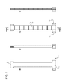
- a ventilator 1 is schematically shown according to the present invention.
- the ventilator 1 comprises a plurality of plates 2, separated one from another by respective spacers 3, an end portion 4 in use placed outside the building, i.e. at low temperature, and an end portion 5 in use placed within the building, i.e. at high temperature.
- the spacers 3 are configured to define the fluidic paths of air flows in heat exchange through the ventilator 1.
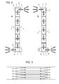
- a path to cool the inside air is defined by an inlet port 6 defined at the end portion 5, an output port 7 defined at the end portion 4 and is illustrated in Figure 2a .
- a path to heat the outside air is defined by an inlet port 8 defined at the end portion 4 and an output port 9 defined at the end portion 5.
- the end portion. 4 has a closed head 10 and transverse to the direction of air flow, and the inlet openings 8 are opposed to the outlet openings 7 with respect to the head 10.
- the end portion 5 has a head 11 transverse to the direction of air flow, and the inlet openings 6 are opposed to the outlet openings 9 with respect to the head 11.
- the inlet openings 6, 8 are opposed to the respective outlet openings 7, 9 for separating the inlet air as much as possible from the outlet air and preventing air recirculation, i.e. exhaust air exiting from the portion 4 is collected by the inlet port 8.
- Each path is also laterally defined by spacers 3 functioning as both a separation of the plates 2 in the direction perpendicular to the plates themselves, and a containment of the air flow.
- the paths are alternately stacked for creating a flow exchange in counterflow as shown in Figure 3 .
- plates 2 are made up of metal segmented radiating elements 2' connected one another in the transverse direction with respect to the airflow direction by a heat-insulating material, such as adhesive tape.
- a heat-insulating material such as adhesive tape.
- each radiating element defines a different temperature from the adjacent radiating elements.
- an high efficiency is achieved by average temperature difference among all the adjacent radiating elements 2' lower than 4°C, preferably about 2°C.
- each plate 2 in perpendicular direction to the plates themselves and the distance between the spacers 3 parallel to the flow direction, bearing in mind the flow rate of the ventilators is such as to define a turbulent airflow.
- the design outside temperature is the average winter season temperature of the area of the building in which the ventilator 1 is mounted, and the inside temperature is 20°C.
- the ventilator 1 comprises a first and a second convector 12 and 13 mounted either on the end portion 4 or on the portion 5.
- the air density is essentially the same (the difference in temperature is below 5°C) and so are flow rates.
- a convector is configured to push the airflow within the respective path and the other convector is configured to draw an airflow out of its respective path.
- the convector 12 pushes air into the cooling path and the convector 13 draws air from the heating path.
- the ventilator 1 was turned on for half an hour before the first survey. This was to allow the equipment to find a balance, since at the beginning of operations it was at a temperature of 20°C.
- the first data recorded still reflected the actual ventilator 1 temperature, with a prevalence in the increasing of the entering air temperature, compared to the exiting one, rightly because the air was warmed in part by the residual heat of the appliance itself. But after the first 5 surveys the situation was stabilised, a sign that the thermal inertia of the ventilator was exhausted.
- the heat exchanger fails to raise the entering air temperature with the same effectiveness as the previous test. Despite further raising of the temperature, by 25.3 °C against 19.0 of the previous test, since the entering air temperature is 36.9 °C, the delta to be covered is still 9.2 °C, which lowers the heat recovered to 75.5% (still an absolutely appreciable fact).
- This second test indicates quite clearly that for thermal delta to be exchanged by more than 20 degrees the number of plates should be increased in sequence at a rate of one plate every 2 degrees of increase.
- the ventilator 1 can be used in enclosed livestock structures (stables, piggeries, etc..) where the air can be vitiated by the presence of noxious gases (carbon dioxide, methane, sulphur dioxide, etc.).
- these gases are produced by the animals respiration and/or the exhalation of dejections produced by animals and/or the exhaust of the machines used on farms.
Landscapes
- Engineering & Computer Science (AREA)
- Mechanical Engineering (AREA)
- General Engineering & Computer Science (AREA)
- Chemical & Material Sciences (AREA)
- Combustion & Propulsion (AREA)
- Physics & Mathematics (AREA)
- Thermal Sciences (AREA)
- Heat-Exchange Devices With Radiators And Conduit Assemblies (AREA)
Applications Claiming Priority (1)
| Application Number | Priority Date | Filing Date | Title |
|---|---|---|---|
| ITTO2010A000276A IT1399414B1 (it) | 2010-04-12 | 2010-04-12 | Dispositivo di ventilazione e di scambio di calore per scambiare aria interna di un edificio/stanza con aria esterna dell'atmosfera. |
Publications (1)
| Publication Number | Publication Date |
|---|---|
| EP2375181A1 true EP2375181A1 (fr) | 2011-10-12 |
Family
ID=43466767
Family Applications (1)
| Application Number | Title | Priority Date | Filing Date |
|---|---|---|---|
| EP11162145A Withdrawn EP2375181A1 (fr) | 2010-04-12 | 2011-04-12 | Ventilateur avec un echangeur de chaleur à contre courant |
Country Status (2)
| Country | Link |
|---|---|
| EP (1) | EP2375181A1 (fr) |
| IT (1) | IT1399414B1 (fr) |
Cited By (2)
| Publication number | Priority date | Publication date | Assignee | Title |
|---|---|---|---|---|
| NL1040842B1 (nl) * | 2014-06-11 | 2016-05-12 | Tcrevolutions Ip B V | Warmte-overdrachtsinrichting. |
| EP3093601A1 (fr) * | 2015-05-11 | 2016-11-16 | Aldes Aeraulique | Echangeur thermique |
Citations (5)
| Publication number | Priority date | Publication date | Assignee | Title |
|---|---|---|---|---|
| GB2091407A (en) * | 1981-01-21 | 1982-07-28 | Tokyo Shibaura Electric Co | Stack plate heat exchanger |
| DE29823852U1 (de) * | 1997-08-26 | 2000-01-27 | Feustle Gerhard | Wärmetauscher |
| EP1249669A2 (fr) * | 2001-04-10 | 2002-10-16 | Building Performance Equipment Inc. | Système de ventilation, échangeur de chaleur, méthode de ventilation d'un local et méthode de fabrication d'un échangeur de chaleur en plastique |
| US20080173433A1 (en) * | 2007-01-22 | 2008-07-24 | Building Performance Equipment, Inc. (A Delaware Corporation) | Energy recovery ventilation |
| EP2068107A1 (fr) * | 2006-09-28 | 2009-06-10 | Panasonic Corporation | Élément d'échange thermique |
-
2010
- 2010-04-12 IT ITTO2010A000276A patent/IT1399414B1/it active
-
2011
- 2011-04-12 EP EP11162145A patent/EP2375181A1/fr not_active Withdrawn
Patent Citations (5)
| Publication number | Priority date | Publication date | Assignee | Title |
|---|---|---|---|---|
| GB2091407A (en) * | 1981-01-21 | 1982-07-28 | Tokyo Shibaura Electric Co | Stack plate heat exchanger |
| DE29823852U1 (de) * | 1997-08-26 | 2000-01-27 | Feustle Gerhard | Wärmetauscher |
| EP1249669A2 (fr) * | 2001-04-10 | 2002-10-16 | Building Performance Equipment Inc. | Système de ventilation, échangeur de chaleur, méthode de ventilation d'un local et méthode de fabrication d'un échangeur de chaleur en plastique |
| EP2068107A1 (fr) * | 2006-09-28 | 2009-06-10 | Panasonic Corporation | Élément d'échange thermique |
| US20080173433A1 (en) * | 2007-01-22 | 2008-07-24 | Building Performance Equipment, Inc. (A Delaware Corporation) | Energy recovery ventilation |
Cited By (3)
| Publication number | Priority date | Publication date | Assignee | Title |
|---|---|---|---|---|
| NL1040842B1 (nl) * | 2014-06-11 | 2016-05-12 | Tcrevolutions Ip B V | Warmte-overdrachtsinrichting. |
| EP3093601A1 (fr) * | 2015-05-11 | 2016-11-16 | Aldes Aeraulique | Echangeur thermique |
| FR3036176A1 (fr) * | 2015-05-11 | 2016-11-18 | Aldes Aeraulique | Echangeur thermique bi-matiere |
Also Published As
| Publication number | Publication date |
|---|---|
| IT1399414B1 (it) | 2013-04-16 |
| ITTO20100276A1 (it) | 2011-10-13 |
Similar Documents
| Publication | Publication Date | Title |
|---|---|---|
| US9222695B2 (en) | Heat exchange ventilator | |
| EP2068107A4 (fr) | Élément d'échange thermique | |
| KR100783599B1 (ko) | 환기장치용 열교환기 | |
| JP2013205007A (ja) | 換気装置 | |
| JP2014505229A (ja) | ペルチェ素子を有する気−液熱交換器を備えた室内空調装置 | |
| EP3032183B1 (fr) | Système de ventilation comprenant pcm | |
| US5000253A (en) | Ventilating heat recovery system | |
| JP3726802B2 (ja) | 床埋込形空調ユニット | |
| CN112582897B (zh) | 储能柜 | |
| EP2375181A1 (fr) | Ventilateur avec un echangeur de chaleur à contre courant | |
| JP2014040991A (ja) | 熱交換素子とそれを用いた熱交換型換気機器 | |
| US20160348940A1 (en) | Adiabatic cooling unit | |
| CN202195544U (zh) | 单跨度空调系统 | |
| KR102173317B1 (ko) | 폐열회수형 환기장치 및 이를 이용한 폐열회수 시스템 | |
| JP2018004115A (ja) | 熱交換形換気装置 | |
| FI127443B (fi) | Kiinteistön energiataseen hallintajärjestelmä | |
| CN216087381U (zh) | 一种监控设备散热装置 | |
| SK288585B6 (sk) | Klimatizačná jednotka s rekuperáciou | |
| JP2017116149A (ja) | 熱交換素子を用いた熱交換形換気装置 | |
| US20110139403A1 (en) | Heat Exchanger | |
| CN205047077U (zh) | 一种保温通风窗户 | |
| CN201819595U (zh) | 热管热交换器及其组合 | |
| FI88331C (fi) | Vaermeaotervinningssystem | |
| JPH01137139A (ja) | 熱交換形換気装置 | |
| NL2023261B1 (en) | Data center cooling |
Legal Events
| Date | Code | Title | Description |
|---|---|---|---|
| PUAI | Public reference made under article 153(3) epc to a published international application that has entered the european phase |
Free format text: ORIGINAL CODE: 0009012 |
|
| AK | Designated contracting states |
Kind code of ref document: A1 Designated state(s): AL AT BE BG CH CY CZ DE DK EE ES FI FR GB GR HR HU IE IS IT LI LT LU LV MC MK MT NL NO PL PT RO RS SE SI SK SM TR |
|
| AX | Request for extension of the european patent |
Extension state: BA ME |
|
| RIN1 | Information on inventor provided before grant (corrected) |
Inventor name: CIGNETTI, ALESSANDRO Inventor name: BECHIS, STEFANO |
|
| STAA | Information on the status of an ep patent application or granted ep patent |
Free format text: STATUS: THE APPLICATION IS DEEMED TO BE WITHDRAWN |
|
| 18D | Application deemed to be withdrawn |
Effective date: 20120413 |