EP3032183B1 - Système de ventilation comprenant pcm - Google Patents
Système de ventilation comprenant pcm Download PDFInfo
- Publication number
- EP3032183B1 EP3032183B1 EP15199943.0A EP15199943A EP3032183B1 EP 3032183 B1 EP3032183 B1 EP 3032183B1 EP 15199943 A EP15199943 A EP 15199943A EP 3032183 B1 EP3032183 B1 EP 3032183B1
- Authority
- EP
- European Patent Office
- Prior art keywords
- air
- temperature
- inbound
- ventilating
- pcm
- Prior art date
- Legal status (The legal status is an assumption and is not a legal conclusion. Google has not performed a legal analysis and makes no representation as to the accuracy of the status listed.)
- Active
Links
Images


Classifications
-
- F—MECHANICAL ENGINEERING; LIGHTING; HEATING; WEAPONS; BLASTING
- F24—HEATING; RANGES; VENTILATING
- F24F—AIR-CONDITIONING; AIR-HUMIDIFICATION; VENTILATION; USE OF AIR CURRENTS FOR SCREENING
- F24F5/00—Air-conditioning systems or apparatus not covered by F24F1/00 or F24F3/00, e.g. using solar heat or combined with household units such as an oven or water heater
- F24F5/0007—Air-conditioning systems or apparatus not covered by F24F1/00 or F24F3/00, e.g. using solar heat or combined with household units such as an oven or water heater cooling apparatus specially adapted for use in air-conditioning
- F24F5/0017—Air-conditioning systems or apparatus not covered by F24F1/00 or F24F3/00, e.g. using solar heat or combined with household units such as an oven or water heater cooling apparatus specially adapted for use in air-conditioning using cold storage bodies, e.g. ice
- F24F5/0021—Air-conditioning systems or apparatus not covered by F24F1/00 or F24F3/00, e.g. using solar heat or combined with household units such as an oven or water heater cooling apparatus specially adapted for use in air-conditioning using cold storage bodies, e.g. ice using phase change material [PCM] for storage
-
- F—MECHANICAL ENGINEERING; LIGHTING; HEATING; WEAPONS; BLASTING
- F24—HEATING; RANGES; VENTILATING
- F24F—AIR-CONDITIONING; AIR-HUMIDIFICATION; VENTILATION; USE OF AIR CURRENTS FOR SCREENING
- F24F11/00—Control or safety arrangements
- F24F11/70—Control systems characterised by their outputs; Constructional details thereof
- F24F11/80—Control systems characterised by their outputs; Constructional details thereof for controlling the temperature of the supplied air
- F24F11/83—Control systems characterised by their outputs; Constructional details thereof for controlling the temperature of the supplied air by controlling the supply of heat-exchange fluids to heat-exchangers
- F24F11/84—Control systems characterised by their outputs; Constructional details thereof for controlling the temperature of the supplied air by controlling the supply of heat-exchange fluids to heat-exchangers using valves
-
- A—HUMAN NECESSITIES
- A01—AGRICULTURE; FORESTRY; ANIMAL HUSBANDRY; HUNTING; TRAPPING; FISHING
- A01K—ANIMAL HUSBANDRY; AVICULTURE; APICULTURE; PISCICULTURE; FISHING; REARING OR BREEDING ANIMALS, NOT OTHERWISE PROVIDED FOR; NEW BREEDS OF ANIMALS
- A01K1/00—Housing animals; Equipment therefor
- A01K1/0047—Air-conditioning, e.g. ventilation, of animal housings
- A01K1/0076—Arrangement of heaters or heat exchangers
-
- F—MECHANICAL ENGINEERING; LIGHTING; HEATING; WEAPONS; BLASTING
- F24—HEATING; RANGES; VENTILATING
- F24F—AIR-CONDITIONING; AIR-HUMIDIFICATION; VENTILATION; USE OF AIR CURRENTS FOR SCREENING
- F24F11/00—Control or safety arrangements
- F24F11/30—Control or safety arrangements for purposes related to the operation of the system, e.g. for safety or monitoring
-
- F—MECHANICAL ENGINEERING; LIGHTING; HEATING; WEAPONS; BLASTING
- F24—HEATING; RANGES; VENTILATING
- F24F—AIR-CONDITIONING; AIR-HUMIDIFICATION; VENTILATION; USE OF AIR CURRENTS FOR SCREENING
- F24F11/00—Control or safety arrangements
- F24F11/70—Control systems characterised by their outputs; Constructional details thereof
- F24F11/72—Control systems characterised by their outputs; Constructional details thereof for controlling the supply of treated air, e.g. its pressure
- F24F11/74—Control systems characterised by their outputs; Constructional details thereof for controlling the supply of treated air, e.g. its pressure for controlling air flow rate or air velocity
- F24F11/76—Control systems characterised by their outputs; Constructional details thereof for controlling the supply of treated air, e.g. its pressure for controlling air flow rate or air velocity by means responsive to temperature, e.g. bimetal springs
-
- F—MECHANICAL ENGINEERING; LIGHTING; HEATING; WEAPONS; BLASTING
- F24—HEATING; RANGES; VENTILATING
- F24F—AIR-CONDITIONING; AIR-HUMIDIFICATION; VENTILATION; USE OF AIR CURRENTS FOR SCREENING
- F24F11/00—Control or safety arrangements
- F24F11/70—Control systems characterised by their outputs; Constructional details thereof
- F24F11/72—Control systems characterised by their outputs; Constructional details thereof for controlling the supply of treated air, e.g. its pressure
- F24F11/74—Control systems characterised by their outputs; Constructional details thereof for controlling the supply of treated air, e.g. its pressure for controlling air flow rate or air velocity
- F24F11/77—Control systems characterised by their outputs; Constructional details thereof for controlling the supply of treated air, e.g. its pressure for controlling air flow rate or air velocity by controlling the speed of ventilators
-
- F—MECHANICAL ENGINEERING; LIGHTING; HEATING; WEAPONS; BLASTING
- F24—HEATING; RANGES; VENTILATING
- F24F—AIR-CONDITIONING; AIR-HUMIDIFICATION; VENTILATION; USE OF AIR CURRENTS FOR SCREENING
- F24F12/00—Use of energy recovery systems in air conditioning, ventilation or screening
- F24F12/001—Use of energy recovery systems in air conditioning, ventilation or screening with heat-exchange between supplied and exhausted air
- F24F12/006—Use of energy recovery systems in air conditioning, ventilation or screening with heat-exchange between supplied and exhausted air using an air-to-air heat exchanger
-
- F—MECHANICAL ENGINEERING; LIGHTING; HEATING; WEAPONS; BLASTING
- F28—HEAT EXCHANGE IN GENERAL
- F28D—HEAT-EXCHANGE APPARATUS, NOT PROVIDED FOR IN ANOTHER SUBCLASS, IN WHICH THE HEAT-EXCHANGE MEDIA DO NOT COME INTO DIRECT CONTACT
- F28D20/00—Heat storage plants or apparatus in general; Regenerative heat-exchange apparatus not covered by groups F28D17/00 or F28D19/00
- F28D20/02—Heat storage plants or apparatus in general; Regenerative heat-exchange apparatus not covered by groups F28D17/00 or F28D19/00 using latent heat
-
- F—MECHANICAL ENGINEERING; LIGHTING; HEATING; WEAPONS; BLASTING
- F28—HEAT EXCHANGE IN GENERAL
- F28D—HEAT-EXCHANGE APPARATUS, NOT PROVIDED FOR IN ANOTHER SUBCLASS, IN WHICH THE HEAT-EXCHANGE MEDIA DO NOT COME INTO DIRECT CONTACT
- F28D21/00—Heat-exchange apparatus not covered by any of the groups F28D1/00 - F28D20/00
- F28D21/0001—Recuperative heat exchangers
- F28D21/0014—Recuperative heat exchangers the heat being recuperated from waste air or from vapors
-
- F—MECHANICAL ENGINEERING; LIGHTING; HEATING; WEAPONS; BLASTING
- F24—HEATING; RANGES; VENTILATING
- F24F—AIR-CONDITIONING; AIR-HUMIDIFICATION; VENTILATION; USE OF AIR CURRENTS FOR SCREENING
- F24F2110/00—Control inputs relating to air properties
- F24F2110/10—Temperature
-
- F—MECHANICAL ENGINEERING; LIGHTING; HEATING; WEAPONS; BLASTING
- F24—HEATING; RANGES; VENTILATING
- F24F—AIR-CONDITIONING; AIR-HUMIDIFICATION; VENTILATION; USE OF AIR CURRENTS FOR SCREENING
- F24F2110/00—Control inputs relating to air properties
- F24F2110/50—Air quality properties
-
- F—MECHANICAL ENGINEERING; LIGHTING; HEATING; WEAPONS; BLASTING
- F24—HEATING; RANGES; VENTILATING
- F24F—AIR-CONDITIONING; AIR-HUMIDIFICATION; VENTILATION; USE OF AIR CURRENTS FOR SCREENING
- F24F2110/00—Control inputs relating to air properties
- F24F2110/50—Air quality properties
- F24F2110/65—Concentration of specific substances or contaminants
- F24F2110/70—Carbon dioxide
-
- F—MECHANICAL ENGINEERING; LIGHTING; HEATING; WEAPONS; BLASTING
- F28—HEAT EXCHANGE IN GENERAL
- F28D—HEAT-EXCHANGE APPARATUS, NOT PROVIDED FOR IN ANOTHER SUBCLASS, IN WHICH THE HEAT-EXCHANGE MEDIA DO NOT COME INTO DIRECT CONTACT
- F28D20/00—Heat storage plants or apparatus in general; Regenerative heat-exchange apparatus not covered by groups F28D17/00 or F28D19/00
- F28D2020/0004—Particular heat storage apparatus
- F28D2020/0013—Particular heat storage apparatus the heat storage material being enclosed in elements attached to or integral with heat exchange conduits
-
- Y—GENERAL TAGGING OF NEW TECHNOLOGICAL DEVELOPMENTS; GENERAL TAGGING OF CROSS-SECTIONAL TECHNOLOGIES SPANNING OVER SEVERAL SECTIONS OF THE IPC; TECHNICAL SUBJECTS COVERED BY FORMER USPC CROSS-REFERENCE ART COLLECTIONS [XRACs] AND DIGESTS
- Y02—TECHNOLOGIES OR APPLICATIONS FOR MITIGATION OR ADAPTATION AGAINST CLIMATE CHANGE
- Y02A—TECHNOLOGIES FOR ADAPTATION TO CLIMATE CHANGE
- Y02A40/00—Adaptation technologies in agriculture, forestry, livestock or agroalimentary production
- Y02A40/70—Adaptation technologies in agriculture, forestry, livestock or agroalimentary production in livestock or poultry
-
- Y—GENERAL TAGGING OF NEW TECHNOLOGICAL DEVELOPMENTS; GENERAL TAGGING OF CROSS-SECTIONAL TECHNOLOGIES SPANNING OVER SEVERAL SECTIONS OF THE IPC; TECHNICAL SUBJECTS COVERED BY FORMER USPC CROSS-REFERENCE ART COLLECTIONS [XRACs] AND DIGESTS
- Y02—TECHNOLOGIES OR APPLICATIONS FOR MITIGATION OR ADAPTATION AGAINST CLIMATE CHANGE
- Y02A—TECHNOLOGIES FOR ADAPTATION TO CLIMATE CHANGE
- Y02A40/00—Adaptation technologies in agriculture, forestry, livestock or agroalimentary production
- Y02A40/70—Adaptation technologies in agriculture, forestry, livestock or agroalimentary production in livestock or poultry
- Y02A40/76—Adaptation technologies in agriculture, forestry, livestock or agroalimentary production in livestock or poultry using renewable energy
-
- Y—GENERAL TAGGING OF NEW TECHNOLOGICAL DEVELOPMENTS; GENERAL TAGGING OF CROSS-SECTIONAL TECHNOLOGIES SPANNING OVER SEVERAL SECTIONS OF THE IPC; TECHNICAL SUBJECTS COVERED BY FORMER USPC CROSS-REFERENCE ART COLLECTIONS [XRACs] AND DIGESTS
- Y02—TECHNOLOGIES OR APPLICATIONS FOR MITIGATION OR ADAPTATION AGAINST CLIMATE CHANGE
- Y02B—CLIMATE CHANGE MITIGATION TECHNOLOGIES RELATED TO BUILDINGS, e.g. HOUSING, HOUSE APPLIANCES OR RELATED END-USER APPLICATIONS
- Y02B30/00—Energy efficient heating, ventilation or air conditioning [HVAC]
- Y02B30/56—Heat recovery units
-
- Y—GENERAL TAGGING OF NEW TECHNOLOGICAL DEVELOPMENTS; GENERAL TAGGING OF CROSS-SECTIONAL TECHNOLOGIES SPANNING OVER SEVERAL SECTIONS OF THE IPC; TECHNICAL SUBJECTS COVERED BY FORMER USPC CROSS-REFERENCE ART COLLECTIONS [XRACs] AND DIGESTS
- Y02—TECHNOLOGIES OR APPLICATIONS FOR MITIGATION OR ADAPTATION AGAINST CLIMATE CHANGE
- Y02B—CLIMATE CHANGE MITIGATION TECHNOLOGIES RELATED TO BUILDINGS, e.g. HOUSING, HOUSE APPLIANCES OR RELATED END-USER APPLICATIONS
- Y02B30/00—Energy efficient heating, ventilation or air conditioning [HVAC]
- Y02B30/70—Efficient control or regulation technologies, e.g. for control of refrigerant flow, motor or heating
-
- Y—GENERAL TAGGING OF NEW TECHNOLOGICAL DEVELOPMENTS; GENERAL TAGGING OF CROSS-SECTIONAL TECHNOLOGIES SPANNING OVER SEVERAL SECTIONS OF THE IPC; TECHNICAL SUBJECTS COVERED BY FORMER USPC CROSS-REFERENCE ART COLLECTIONS [XRACs] AND DIGESTS
- Y02—TECHNOLOGIES OR APPLICATIONS FOR MITIGATION OR ADAPTATION AGAINST CLIMATE CHANGE
- Y02E—REDUCTION OF GREENHOUSE GAS [GHG] EMISSIONS, RELATED TO ENERGY GENERATION, TRANSMISSION OR DISTRIBUTION
- Y02E60/00—Enabling technologies; Technologies with a potential or indirect contribution to GHG emissions mitigation
- Y02E60/14—Thermal energy storage
-
- Y—GENERAL TAGGING OF NEW TECHNOLOGICAL DEVELOPMENTS; GENERAL TAGGING OF CROSS-SECTIONAL TECHNOLOGIES SPANNING OVER SEVERAL SECTIONS OF THE IPC; TECHNICAL SUBJECTS COVERED BY FORMER USPC CROSS-REFERENCE ART COLLECTIONS [XRACs] AND DIGESTS
- Y02—TECHNOLOGIES OR APPLICATIONS FOR MITIGATION OR ADAPTATION AGAINST CLIMATE CHANGE
- Y02P—CLIMATE CHANGE MITIGATION TECHNOLOGIES IN THE PRODUCTION OR PROCESSING OF GOODS
- Y02P60/00—Technologies relating to agriculture, livestock or agroalimentary industries
- Y02P60/12—Technologies relating to agriculture, livestock or agroalimentary industries using renewable energies, e.g. solar water pumping
-
- Y—GENERAL TAGGING OF NEW TECHNOLOGICAL DEVELOPMENTS; GENERAL TAGGING OF CROSS-SECTIONAL TECHNOLOGIES SPANNING OVER SEVERAL SECTIONS OF THE IPC; TECHNICAL SUBJECTS COVERED BY FORMER USPC CROSS-REFERENCE ART COLLECTIONS [XRACs] AND DIGESTS
- Y02—TECHNOLOGIES OR APPLICATIONS FOR MITIGATION OR ADAPTATION AGAINST CLIMATE CHANGE
- Y02P—CLIMATE CHANGE MITIGATION TECHNOLOGIES IN THE PRODUCTION OR PROCESSING OF GOODS
- Y02P60/00—Technologies relating to agriculture, livestock or agroalimentary industries
- Y02P60/50—Livestock or poultry management
Definitions
- the invention relates to a ventilation assembly comprising PCM, a method for ventilating a building or a room in a building, a heat exchanger for a ventilation assembly, and a control device for a ventilation assembly.
- a ventilation assembly may have been installed in a building or a part thereof, for the supply and/or discharge of air.
- a ventilation assembly may be part of a climate system for controlling an indoor climate in a building, but in some cases also form the climate system.
- WO2003/102484 relates to conditioning air in the room of a building in terms of heat and/or cold and optionally humidity.
- the abstract supplied air flows into the room of the building and the extracted air is conducted out of said room, whereby a sensitive recuperative heat exchange is carried out between the supplied air and the extracted air, preferably prior to the influx of supplied air and after the discharge of extracted air from the room of the building.
- Said latent heat accumulator bodies can be located in particular in the vicinity of the ceiling.
- Thermal buffer elements that operate by means of latent heat can furthermore be provided.
- WO2009/101398 describes a transportable PCM (phase change material) module comprising a number of PCM packs; a housing for thermally insulting [... insulating] said number of PCM packs from a module's surrounding medium; spaces separating said packs and forming one or more channels for the flow of a fluid; said housing incorporating a fluid inlet and a fluid outlet; whereby, in use, fluid flows through said channels from said inlet to said outlet.
- a PCM (phase change material) pack comprises a laminate of a first conducting panel and a second conducting panel enclosing a portion consisting primarily of PCM; wherein said portion of PCM incorporates thermal conductors.
- phase change material also called PCM
- the invention provides a ventilation assembly according to claim 1.
- the invention further provides a method according to claim 10.
- the second air supply flow rate is at least twice as large as the first air supply flow rate. It has turned out that at such a difference a good heat recovery effect can be achieved in combination with a setting for heating or cooling by means of energy storage in the PCM material.
- the air displacement device in the first setting, has been set for a balanced ventilation.
- the air displacement device in the second setting, has been set for a balanced ventilation.
- the air displacement device comprises an inbound air displacement device for displacing inbound ventilating air and an outbound air displacement device for displacing outbound ventilating air. In that way the operation between various settings can be set and optimal use can be made of the PCM material at a reduced use of energy.
- control device is functionally coupled to the air displacement device for influencing the air flow rates.
- the ventilation assembly has furthermore been provided with flow limitation devices, in particular valves, functionally coupled to the control device, for influencing the air flow rates.
- flow limitation devices in particular valves, functionally coupled to the control device, for influencing the air flow rates.
- the ventilation assembly has furthermore been provided with flow limitation devices, in particular valves, functionally coupled to a control device, and wherein the control device has been functionally coupled to the air displacement device, for influencing the air flow rates by setting the flow limitation devices, the air displacement device, or a combination thereof.
- the control device is able to control the flow rates by means of the valves and air displacement devices, for instance to be coupled to temperatures to be measured, and for instance the capacity and status of the PCM material.
- the inbound and outbound ventilating air are separated in the heat exchanger by means of PCM material, in particular PCM elements, wherein in particular the PCM elements comprise a container of synthetic material, which container is provided with PCM material.
- PCM material in particular PCM elements
- the PCM elements comprise a container of synthetic material, which container is provided with PCM material.
- the ventilation assembly has further been provided with a temperature sensor for the outbound ventilating air and a temperature sensor for the inbound ventilating air, functionally coupled to the control device, wherein in response to a temperature difference the control device sets the ventilation assembly in the first setting or in the second setting, in particular when the temperature of the inbound ventilating air has a temperature exceeding a set-temperature, and the outbound ventilating air has a temperature exceeding the set-temperature.
- Functional coupling means, as in other situations, that the parts are able to work together and are able to carry out a joint function. For that purpose, for instance parts may be connected to each other, engage onto each other, drive each other, exchange data wirelessly, and such.
- control device By means of functionally coupled temperature sensors, the control device is able take temperatures and on the basis thereof control or even adjust.
- control device has been provided with a status indicator of the PCM material in the heat exchanger, wherein the status indicator indicates a charged or discharged condition of the PCM material.
- the status indicator indicates a charged or discharged condition of the PCM material.
- the PCM material has been selected from PCM having a melting temperature that differs a maximum of 2 degrees from a set-temperature, in particular PCM having a melting temperature that differs a maximum of 1 degree from a set-temperature.
- the heat exchanger may furthermore comprise a first adjustment device comprising a first or heat recovery setting in which circulation through the third fluid connection has been blocked, and a second setting in which circulation from the second inlet to the second fluid connection has been blocked.
- the first inlet for inbound ventilating air has been connected to one end of the first fluid connection.
- the adjustment device brings the first inlet in fluid connection with the end of the second fluid connection and the first outlet with the other end of the second fluid connection, so that inbound ventilating air is able to get into heat exchanging contact with the elements.
- the invention further relates to a method for ventilating a building or a room in a building by means of the ventilation assembly, wherein in a first setting inbound and outbound ventilating air are brought in heat exchanging contact with each other, wherein they are substantially separated by PCM material, and in a second setting inbound ventilating air is brought in heat exchanging contact with the PCM material and outbound ventilating air bypasses the PCM material, wherein it does not exchange heat with the PCM material and does not exchange heat with the inbound ventilating air.
- the PCM material has been provided in elements filled with PCM material, wherein the inbound ventilating air is brought substantially in contact with one side of the elements and the outbound ventilating air is brought in contact with the other side of the elements, wherein the thickness of the elements has been chosen such that the air-PCM heat exchanger will after a while act like a counterflow heat exchanger having a substantially constant heat transfer.
- a flow rate of inbound and outbound ventilating air is lowered to a set minimum ventilating level.
- a measured outdoor air temperature exceeds a set heating threshold temperature and a measured air supply temperature is lower than a set thermally comfortable air supply temperature and a measured indoor air temperature exceeds a set-temperature, air flow rates of inbound ventilating air and outbound ventilating air are increased.
- the outdoor air temperature exceeds a set heating threshold temperature and an air temperature of the building or the ventilating air flowing into the room exceeds a thermally comfortable air supply temperature and an indoor air temperature exceeds the set-temperature and an indoor air temperature exceeds an outdoor air temperature, substantially all inbound ventilating air is brought into heat exchanging contact with the elements filled with PCM material, in particular the inbound ventilating air substantially flows around the elements filled with PCM.
- the outbound ventilating air is passed partially along and in heat exchanging contact with the elements filled with PCM material and is passed partially around the elements filled with PCM without exchanging heat with them.
- the method relates to a method for ventilating a broiler house provided with the ventilation assembly.
- a good use of PCM material is possible, and a heat exchanger that can be cleaned well can be made.
- the method relates to a method for ventilating a commercial and industrial building provided with the ventilation assembly.
- the invention further relates to a control device for a ventilation assembly provided with a computer processor and computer program for, when running on the computer processor, carrying out the above-mentioned method.
- the ventilation assembly or the method relates to the use of air-PCM heat exchangers in the built-up environment in general, for instance in the agricultural sector, industrial building, commercial building and residential building.
- the assembly and the method are for instance highly suitable for the ventilation, cooling and heating of broiler houses.
- phase changing material in an air-PCM heat exchanger phase changing material, further referred to as PCM, for instance serves as energy storage wherein it may serve as cooling agent, but it can also discharge stored heat and then serves as heating agent.
- the PCM contains a mixture of salt and water.
- PCM may contain an organic or inorganic material.
- the PCM material contains calcium chloride hexahydrate. This has also been described in the above-mentioned references. During solidifying the PCM is cooled and the environment heated. During melting the PCM is heated and the environment cooled.
- the ventilation assembly comprises PCM having a transition temperature of approximately 20-30°C. In one embodiment the PCM has a transition temperature of 22-27°C. For the Dutch climate a ventilation assembly in one embodiment comprises PCM having a transition temperature of approximately 23°C-25°C. In warmer regions a melting temperature exceeding these values will be selected. In other climatic zones, the melting temperature to be set is a function of the climatic zone in question. In the explanation below all this will be further elucidated.
- a device or heat exchanger as described in PCT/NL2012/050544 can be used.
- PCM PCM or the panels as described in WO2013191554 can be used.
- the invention further relates to a ventilation assembly as described in this description or according to the claims.
- substantially as used herein will be clear to the expert.
- the term “substantially” may also comprise an embodiment with “fully”, “all” and the like.
- the adjective “substantially” may also be left out.
- the term “substantially” may relate to 90% or more, such as 95% or more, in particular 99% or more, more in particular 99.5% or more, comprising 100%.
- the invention can be implemented by means of hardware comprising several distinguishing characteristics, and by means of a suitably programmed computer.
- several such means can be provided by one and the same piece of hardware.
- the mere fact that several measures have been summed up in various dependent claims does not mean that a combination of these characteristics cannot be used advantageously.
- the invention furthermore relates to a device, method or process provided with one or more of the characterising measures described in the attached description and/or shown in the attached drawings.
- FIG. 1 schematically shows a ventilation assembly 1 for a building 40, for instance a broiler house or an office building.
- the ventilation assembly 1 has been provided with air displacement devices, here by way of example a speed-controlled ventilator 3 for the outbound air and a speed-controlled ventilator 4 for the inbound air.
- the ventilation assembly 1 has furthermore been provided with a control device 5.
- the control device 5 measures the temperature in building 40, and optionally comprises a further sensor for the content of carbon dioxide, or ammonia, in the indoor air, as an indication of indoor air pollution. Sensors may also be used for other air pollutions of the indoor air.
- the control device 5 has in this case been functionally coupled to the air displacement devices 3, 4 for enabling the setting of an air flow rate of inbound and outbound air.
- the control device 5 has furthermore been operationally connected to valves 14, 15, 16, 17, 18 and 19.
- the control device can be connected to temperature sensors T1, T2 and/or T3 as shown. Either by means of wiring or wirelessly, the control device 5 can be connected to the various parts.
- a connection to valve 18 has not been shown here, but may of course be present indeed. Valves may, if so desired, also be combined.
- the ventilation assembly has been provided with a heat exchanger 2 provided with PCM material 30. It regards an easy-to-clean air-PCM heat exchanger consisting of polypropylene (PP) of polyethylene (for instance HDPE) panels 30 filled with PCM material. Said heat exchangers have a low air resistance, for instance 20-30 Pascal.
- PP polypropylene
- HDPE polyethylene
- the heat exchanger 2 has been provided with panels with PCM material 30 which in a first setting ('traditional' heat exchanger) separate air flows from each other in a heat exchanging (or heat recovering) manner.
- air of one of either flows flows along the panels with PCM 30 so that the temperature of the air flow is able to change temperature due to exchange of energy with the panels with PCM.
- the single air flow is heated or cooled.
- Heat exchanger 2 has a building-side outlet 20, a building-side inlet 21, an inlet 10 for (fresh) air from the outside of the building 40 and an outlet 11 for discharging air out of the building.
- the ventilation assembly 1 further has a bypass channel 22 connecting building-side outlet 21 to the outlet 11 bypassing the heat exchanger 2. In that way in one setting, air leaving the building can bypass the heat exchanger 2. Building-side outlet 21 thus can be short-circuited with outlet 23.
- control valves 14, 15, 16, 17, that are functionally connected to control device 5 it can be set whether air flows via and through the heat exchanger 2, or bypasses it via bypass channel 22.
- air can be introduced into a building or a room in a building.
- air also referred to as 'room air'
- 'room air' can be discharged out of a building or a room in a building.
- bypass channel 22 said air can also be discharged immediately out(side) of the building.
- Outdoor air inlet 10 has been connected to an inlet of the heat exchanger 2 for letting in (fresh) outdoor air into a building.
- An outlet 11 has been connected to (heat exchanger) outlet 23.
- the heat exchanger 2 provided with PCM material, either building-side outbound air (room air) is able to exchange heat with inbound air.
- the heat exchanger 2 then functions as a 'traditional' heat recovery device. However, this does not include the time delay occurring in the process and additional heating made possible as compared to the traditional heat recovery apparatus. This mostly occurs in discontinuous situations. For instance, in office buildings ventilation and temperature control is required during office hours. Outside office hours this is required to a limited extent only, if at all.
- the temperature will be relatively high and the PCM material has absorbed relatively much heat.
- said stored heat can be used to pre-heat the relatively cool outdoor air. This can also take place in the first setting.
- the inbound outdoor air will then be relatively cool, the indoor air will usually be warmer, and the PCM material will be even warmer, relatively speaking, and able to give off heat.
- bypass channel 22 becomes operational, and room air will bypass the heat exchanger 2.
- Inbound outdoor air will be directed along the PCM in the heat exchanger 2 and depending on the condition/temperature of the PCM material in the heat exchanger 2 either be cooled during the day and heated during the night.
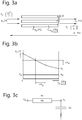
- FIG. 3A a flow channel for inbound (outdoor) air is shown.
- the air flows along PCM elements 30.
- FIG. 2A an inbound (outdoor) air flow and an outbound (indoor) air flow are in counterflow with each other. For each only one channel is shown. A flow flows along one side of a PCM element and the other flow flows along the opposite side of said PCM element 30. The flows exchange energy via a PCM element 30 (and therefore via the PCM therein).
- Figure 3B shows a curve showing the relation between the temperature and the specific capacity of the PCM.
- Figure 2A shows the heat exchanger during the first setting.
- Ventiler house In the following numerical calculations for an office building the successive parameters will be discussed again.
- One embodiment of the ventilation assembly regards the use in a broiler house. Below, such a use and design considerations will be discussed first. Then a use in for instance a commercial and industrial building will be discussed, and design considerations will be given.
- chicks weighing 40 g can be fattened into broilers weighing 2.4 k in a time span of 42 days. In a broiler house an annual maximum of approximately 8 fattening cycles may take place.
- the comfortability temperature of chicks is approximately 33°C and for adult broilers approximately 20°C. When there is sufficient air movement in the chicken's living zone, the comfortability temperature due to the wind chill factor can be increased from 20°C to 25°C and maybe even more. Regarding young chicks this means minimum air movement and maximum heat recovery, and regarding adult broilers maximum air movement and maximum cooling.
- a traditional ventilation assembly then functions as follows. In the first week the ventilation assembly runs at a minimum ventilation flow rate in order to discharge the waste products of the chicks (CO 2 , Ammonia). The heating device will perhaps be operational at full load to keep the broiler house at a temperature of 33°C. In the last week on the other hand, when the adult broilers are mature, the heating device will no longer be operational. The broiler house will then be ventilated at more than the minimum level, meaning at a larger flow rate than required for discharging waste materials. Using, or because of, the wind chill factor, the ventilation assembly starts functioning like a cooling installation at an excess (excess flow rate) of ventilating air. An air supply flow rate of 13 to 15 m 3 /h per chicken, a standard value in traditional installations for broiler houses, will then be insufficient to realise the ideal indoor temperature and additional cooling will need to be provided for.
- a broiler fattening cycle in one embodiment takes 42 days (6 weeks). In said 42 days, chicks are fattened into broilers. During said cycle the ideal indoor temperature of the broiler houses changes according to the table below. Week Ideal temperature [°C] Ideal temperature (incl. 'chill effect') [°C] 0 33 33 1 30 31.5 2 27 30 3 24 29 4 21 27.5 5 19 26 6 18 25
- the first situation is the heating of the broiler houses containing 1-week old chicks in wintry conditions at a minimum ventilation flow rate.
- the second situation is cooling the broiler houses with 6-week old mature broilers in summery conditions with an excess of air in connection with the wind chill factor. It turned out that by using a ventilation assembly with PCM-heat recovery the air supply air flow can be lower than in traditional installations. It turned out that the air supply flow rate in one embodiment had been halved or was even three times as low for realising the same daytime indoor temperature as in a traditional installation.
- FIG. 4a A further example of the ventilation assembly is discussed below for a building such as an office building, but also the above-mentioned broiler house.
- the ventilation assembly is also referred to as 'PCM high efficiency-heat recovery ventilator convector'.
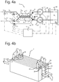
- FIG. 4a and 5s such an assembly is shown in two different operating conditions.
- FIG. 4b and 5b settings of a possible embodiment of the heat exchanger 2 for the set-up of figures 4a and 5a , respectively, are shown.
- the valves 14, 16 and 17 are for instance slides blocking the passages/channels. Dotted lines represent opened, hatched lines represent closed.
- the PCM elements 30 have also been shown, and for instance each one or more PCM elements as described in WO2013191554 .
- the embodiment regards a PCM high efficiency-heat recovery ventilator convector with wintry heat recovery and summery cooling.
- the PCM high efficiency-heat recovery ventilator convector is in this case for instance dimensioned for summery full load cooling operation. Subsequently the seasonal operation is described taking full load wintry heating as starting point.
- starting point is one OC AUTARKIS 198 mm HDPE panel (for instance described in WO2013191554 , herein included by reference or as if fully copied) filled with 'PCM 23', meaning a melting temperature of approximately 23°C, and an adjacent air slit of 3-5 mm, specifically approximately 4 mm.
- the calculation relates to an office floor area of 10 m 2 having a perceptible cooling load of 50 W/m 2 (95% of the offices).
- Dimensions HDPE panel. [ m ] d p ⁇ l p ⁇ b p 0.013 ⁇ 0.570 ⁇ 0.198 Heating surface panel [ m 2 ]
- the minimum required ventilation flow rate in offices for instance is 30 m 3 h . person with one person per 10 square meter.
- the flow rate of the PCM ventilator convector is adjusted back from 252 m 3 h (see dimensioning summer) to 30 m 3 h .
- the forced convective heat transfer remains approximately the same as during cooling.
- the air-PCM heat exchanger now functions as high efficiency heat recovery.
- the outdoor air temperature is too low to be supplied directly to the room as comfortable air supply temperature. It needs to be heated by means of the high efficiency heat recovery operation.
- the flow rate (by means of number of revolutions) of both ventilators now needs to be increased to full load operation while maintaining the heat recovery mode. Contrary to the dimensioning for full load cooling operation the air speed between the slits increases from 0.44 naar 0.88 m s . It still regards laminar flow.
- the air supply temperature therefore will be 18.5°C.
- the air-PCM heat exchanger 2 is dimensioned for the summery cooling situation. In the example for instance 600 m 3 /h for 20 m 2 of office floor area in the Netherlands. This setting is shown in figures 5A and 5B . Outdoor air inlet 10 has now been coupled to inlet channel so that all inbound outdoor air now contacts the PCM and can be cooled. Building-side inbound ventilating air channel 21 has now been coupled to outlet channel 11.
- valves 14, 15, 16, 17 that are among others shown in the figure 1 , 4A and 5A can be designed as combined slides as schematically shown in figures 4B and 5B .
- outdoor air 21 enters and the slides 17 are open.
- the air flows along a side of PCM elements 30 and leaves the heat exchanger 2 at arrows 11.
- Air from the building, indicated by arrows 10 passes through the open slides, shown in hatched lines.
- Slides 14 (in dotted lines) are closed.
- the air, indicated with arrows 20, leaves the heat exchanger 2, via open slides, indicated in dotted lines.
- the other slides, indicated in hatched lines are closed on this side.
- the air from the building flows along another side of the PCM elements 30 than the inbound air does. Both flows are largely in counterflow with each other, and exchange energy via the PCM elements 30.
- FIG 5B the air from the building bypasses the heat exchanger 2 via fluid connection 22.
- the slides 17 are now closed. All other slides are now open, that means both the slides 14 and the slides at the opposing upper end.
- Five arrows 10 are now inbound and five arrows 20 are outbound.
- the cross-sectional area of the inbound air through the heat exchanger now is larger than in the first setting according to figure 4B .
- the cross-sectional area for the fluid connection for the inbound air from outside of the building in the second setting of figure 5B is at least twice as large as in the first setting according to figure 4B .
- openings in the heat exchanger 2 may also be positioned such that one of either flows 10, 20, the inbound flow 10 or outbound flow 20, that exit the heat exchanger at the upper side in the depiction, can also flow out at the bottom side of the heat exchanger 2.
- the control of the ventilation assembly for an office building may be as follows: First setting: ventilating and full load heating by heat recovery by means of a PCM heat exchanger. This corresponds to what has been described above in 2.1.
- Flow rate supplied air equals flow rate discharged air. If for instance a measured outdoor air temperature T2 is lower than a (set) heating threshold the supply and discharge ventilators 3, 4 are adjusted back (the flow rate is lowered for instance by lowering the number of revolutions) to a minimum ventilation level. Said minimum corresponds to a set minimum ventilation flow rate.
- the valves 14, 16 and 18 close and valves 15, 17 and 19 open. If the measured temperature T1 in the building or a room is lower than the set heating temperature or a set or 'setpoint' temperature an additional heating becomes operational if so desired.
- T2 exceeds the heating threshold and T3 exceeds the thermally comfortable air supply temperature and T1 exceeds the 'setpoint' temperature and T1 exceeds T2, then the valves 14, 16 and 18 are opened and valves 15, 17 and 19 are closed.
- T2 exceeds the heating threshold and T3 exceeds the thermally comfortable air supply temperature and T1 exceeds the 'setpoint' temperature and T1 is smaller than or equal to T2, then the valve 14 is opened and valve 15 is partially closed to a stop limit.
- T2 exceeds the heating threshold and T3 exceeds the thermally comfortable air supply temperature and T1 exceeds the 'setpoint' temperature and T1 is smaller than or equal to T2, then the valve 14 is opened and valve 15 is partially closed to a stop limit.
Landscapes
- Engineering & Computer Science (AREA)
- Mechanical Engineering (AREA)
- General Engineering & Computer Science (AREA)
- Chemical & Material Sciences (AREA)
- Combustion & Propulsion (AREA)
- Physics & Mathematics (AREA)
- Fluid Mechanics (AREA)
- Life Sciences & Earth Sciences (AREA)
- Environmental Sciences (AREA)
- Thermal Sciences (AREA)
- Zoology (AREA)
- Animal Husbandry (AREA)
- Biodiversity & Conservation Biology (AREA)
- Sustainable Development (AREA)
- Ventilation (AREA)
- Air Conditioning Control Device (AREA)
- Building Environments (AREA)
Claims (14)
- Ensemble de ventilation (1) pour un bâtiment, comprenant:- un échangeur de chaleur (2) pour amener l'air de ventilation entrant et l'air de ventilation sortant en contact d'échange thermique l'un avec l'autre, et muni d'un matériau PCM (30);- un dispositif de déplacement d'air (3, 4) pour mettre l'air de ventilation en mouvement;- un dispositif de commande (5) comprenant un processeur d'ordinateur, etant fonctionnellement couplé à l'échangeur de chaleur (2) et au dispositif de déplacement d'air (3, 4), pourvu d'un débit minimum de ventilation et configuré pour mettre l'ensemble de ventilation (1) dans:- un premier réglage dans lequel l'air de ventilation entrant a un premier débit d'air entrant, l'air de ventilation sortant a un premier débit d'évacuation d'air, l'air de ventilation entrant et sortant sont amenés en chaleur échangeant contact mutuel dans l'échangeur de chaleur (2) au moins partialement avec le matériau PCM (30), et- un deuxième réglage dans lequel l'air de ventilation entrant a un second débit d'alimentation en air et dans l'échangeur de chaleur (2) est sensiblement en contact d'échange de chaleur avec le matériau PCM (30), dans lequel la ventilation entrante et sortante l'air ne se trouve pas en contact d'échange de chaleur dans l'échangeur de chaleur (2), et dans lequel le second débit d'alimentation en air dépasse l'exigence minimale de débit de ventilation pour créer un refroidissement supplémentaire.
- Ensemble de ventilation selon la revendication 1, dans lequel le second débit d'alimentation en air est au moins deux fois plus grand que le premier débit d'alimentation en air.
- Ensemble de ventilation (1) selon la revendication 1 ou 2, dans lequel, dans le premier et / ou le deuxième réglage, le dispositif de déplacement d'air a été réglé pour une ventilation équilibrée.
- Ensemble de ventilation (1) selon l'une quelconque des revendications précédentes, dans lequel le dispositif de déplacement d'air comprend un dispositif de déplacement d'air entrant pour déplacer l'air de ventilation entrant et un dispositif de déplacement d'air sortant pour déplacer l'air de ventilation sortant.
- Ensemble de ventilation (1) selon l'une quelconque des revendications précédentes, dans lequel l'air de ventilation entrant et sortant est séparé dans l'échangeur de chaleur (2) au moyen de matériau PCM (30), en particulier d'éléments PCM, notamment des éléments PCM comprend un récipient en matière synthétique, lequel récipient est muni d'un matériau PCM.
- Ensemble de ventilation (1) selon l'une quelconque des revendications précédentes, comportant en outre un capteur de température pour l'air de ventilation sortant et un capteur de température pour l'air de ventilation entrant, fonctionnellement couplé au dispositif de commande (5), en réponse à différence de température le dispositif de commande (5) règle l'ensemble de ventilation (1) dans le premier ou dans le second réglage, notamment lorsque la température de l'air de ventilation entrant a une température supérieure à une température de consigne, et l'air de ventilation sortant une température dépassant la température de consigne.
- Ensemble de ventilation (1) selon l'une quelconque des revendications précédentes, dans lequel l'échangeur de chaleur (2) comprend:- une série d'éléments munis de matériau PCM;- au moins trois connexions fluidiques, dont une première connexion fluidique est en contact d'échange thermique avec un côté des éléments, une seconde liaison fluidique est en contact d'échange thermique avec un autre côté des éléments tel que l'échange thermique entre le premier et le second fluide la connexion s'effectue via le matériau PCM dans les éléments, et une troisième connexion de fluide qui n'est pas en chaleur échangeant le contact avec les éléments;- au moins une première entrée pour l'air de ventilation entrant, qui se raccorde à une extrémité de la première connexion de fluide;- au moins une première sortie pour l'air de ventilation entrant, qui se raccorde à une autre extrémité de la première connexion de fluide;- au moins une deuxième entrée pour l'air de ventilation sortant, qui se raccorde à une extrémité de la deuxième connexion de fluide et à une extrémité de la troisième connexion de fluide;- au moins une deuxième sortie pour l'air de ventilation sortant, qui se raccorde à une autre extrémité de la deuxième connexion de fluide et à une autre extrémité de la troisième connexion de fluide;- un premier dispositif de réglage comprenant un premier réglage de récupération de chaleur dans lequel la circulation à travers la troisième connexion de fluide a été bloquée, et un second réglage dans lequel la circulation de la seconde entrée à la deuxième connexion de fluide a été bloquée;- dans lequel dans le deuxième réglage, l'air de ventilation sortant est dévié par l'intermédiaire du dispositif de déviation.
- Ensemble de ventilation (1) selon l'une quelconque des revendications précédentes, dans lequel l'échangeur de chaleur (2), dans le second réglage, la première entrée pour l'air de ventilation entrant est connectée à une extrémité de la première connexion de fluide, le second réglage du dispositif de réglage l'entrée dans la connexion fluidique avec l'extrémité de la deuxième connexion de fluide et la première entrée avec l'autre extrémité de la deuxième connexion de fluide, de sorte que l'air de ventilation entrant peut entrer en contact d'échange de chaleur avec les éléments.
- Ensemble de ventilation (1) selon l'une quelconque des revendications précédentes, dans lequel l'échangeur de chaleur (2) comprend en outre:- un premier dispositif de déplacement d'air pour mettre en mouvement l'air de ventilation entrant;- un deuxième dispositif de déplacement d'air pour mettre en mouvement l'air de ventilation sortant.
- Procédé pour ventiler un bâtiment ou une pièce dans un bâtiment au moyen de l'ensemble de ventilation (1) selon l'une quelconque des revendications précédentes, dans lequel, dans un premier réglage, l'air de ventilation entrant et sortant sont amenés en contact d'échange de chaleur, ils sont séparés par un matériau PCM, et dans un second réglage, l'air de ventilation entrant est amené en contact d'échange de chaleur avec le matériau PCM et l'air de ventilation sortant contourne le matériau PCM dans lequel il n'échange pas de chaleur avec le matériau PCM et n'échange pas de chaleur avec l'air de ventilation entrant.
- Procédé selon la revendication précédente, dans lequel le matériau PCM a été fourni dans des éléments remplis de matériau PCM dans lequel l'air de ventilation entrant est amené sensiblement en contact avec un côté des éléments et l'air de ventilation sortant est amené en contact avec l'autre côté de les éléments, dans lesquels l'épaisseur des éléments a été choisie de sorte que l'échangeur de chaleur à air-PCM (2) agisse après un certain temps comme un échangeur de chaleur à contre-courant ayant un transfert de chaleur sensiblement constant.
- Procédé selon l'une quelconque des revendications précédentes 10-11, dans lequel, dans le premier réglage, lorsqu'une température d'air extérieure mesurée est inférieure à une température seuil de chauffage réglée, un débit d'air de ventilation entrant et sortant est abaissé à une ventilation minimum réglée où, dans le premier réglage, lorsqu'une température d'air extérieure mesurée dépasse un seuil de chauffage réglé et qu'une température d'alimentation en air mesurée est inférieure à une température d'alimentation en air thermiquement réglée et une température d'air intérieur mesurée dépasse une température les débits d'air de ventilation entrant et d'air de ventilation sortant sont augmentés.
- Procédé selon l'une quelconque des revendications précédentes 10-11, dans lequel la température de l'air extérieur dépasse un seuil de chauffage réglé et une température de l'air du bâtiment ou de l'air de ventilation s'écoulant dans la pièce dépasse une alimentation en air thermiquement confortable la température et la température de l'air intérieur dépassent la température fixée et la température de l'air intérieur dépasse la température de l'air extérieur, la quasi-totalité de l'air entrant est amenée en contact échangeur de chaleur avec les éléments remplis de matériau PCM. les éléments remplis de PCM, où le second réglage si la température de l'air extérieur dépasse une température de seuil de chauffage réglée et la température de l'air du bâtiment ou de l'air de ventilation circule dans la pièce la température de consigne et la température de l'air intérieur sont inférieure ou égale à la température de l'air extérieur, l'air de ventilation sortant est partiellement passé et en contact d'échange de chaleur avec les éléments remplis de matériau PCM et passe partiellement autour des éléments remplis de PCM sans échanger de chaleur avec eux.
- Programme informatique pour un dispositif de commande (5) pour un ensemble de ventilation (1) qui, si exécuté sur le processeur d'ordinateur du dispositif de commande (5) de l'ensemble de ventilation (1) selon l'une quelconque des revendications précédentes 1-9, fait le procédé selon l'une quelconque des revendications précédentes 10-13.
Applications Claiming Priority (1)
| Application Number | Priority Date | Filing Date | Title |
|---|---|---|---|
| NL2013976A NL2013976B1 (nl) | 2014-12-12 | 2014-12-12 | Ventilatiesamenstel omvattende PCM. |
Publications (2)
| Publication Number | Publication Date |
|---|---|
| EP3032183A1 EP3032183A1 (fr) | 2016-06-15 |
| EP3032183B1 true EP3032183B1 (fr) | 2018-06-06 |
Family
ID=52774459
Family Applications (1)
| Application Number | Title | Priority Date | Filing Date |
|---|---|---|---|
| EP15199943.0A Active EP3032183B1 (fr) | 2014-12-12 | 2015-12-14 | Système de ventilation comprenant pcm |
Country Status (2)
| Country | Link |
|---|---|
| EP (1) | EP3032183B1 (fr) |
| NL (1) | NL2013976B1 (fr) |
Cited By (1)
| Publication number | Priority date | Publication date | Assignee | Title |
|---|---|---|---|---|
| CN110278687A (zh) * | 2019-06-14 | 2019-09-24 | 魏晅 | 一种用于机房环境的综合节能降温控制方法 |
Families Citing this family (7)
| Publication number | Priority date | Publication date | Assignee | Title |
|---|---|---|---|---|
| DK179435B1 (da) * | 2016-12-13 | 2018-07-27 | Skov A/S | Fremgangsmåde til måling af chill i ventilerede staldanlæg, samt sensorelement |
| DE102017120811A1 (de) * | 2017-09-08 | 2019-03-14 | Voltair Gmbh | Wärmetauschvorrichtung |
| CN107763789B (zh) * | 2017-11-17 | 2023-11-03 | 四川大学 | 全热交换新风系统 |
| EP3769015B1 (fr) * | 2018-03-23 | 2024-08-14 | Lead Leroy Concept | Dispositif de ventilation pour bâtiment d'élevage, notamment d'élevage avicole, comprenant un échangeur de chaleur et des moyens de chauffage de l'air |
| FR3079108A1 (fr) * | 2018-03-23 | 2019-09-27 | Lead Leroy Concept | Dispositif de ventilation pour batiment d'elevage, notamment d'elevage avicole, comprenant un echangeur de chaleur et des moyens de chauffage de l'air |
| CH716214B1 (fr) * | 2019-05-24 | 2024-02-29 | Haute Ecole Dlngenierie Et Darchitecture Fribourg | Échangeur thermique pour réguler la température interne d'une ou plusieurs pièces d'un bâtiment. |
| CN116231670B (zh) * | 2023-05-08 | 2023-07-14 | 四川大学 | 计及占用影响的集成楼宇hvac负荷群配电网优化方法 |
Family Cites Families (5)
| Publication number | Priority date | Publication date | Assignee | Title |
|---|---|---|---|---|
| AU2003242612A1 (en) * | 2002-06-03 | 2003-12-19 | Arcadis Bouw En Vastgoed Vestiging | Method for heating and cooling a room and a building with a plurality of rooms |
| NL2000253C2 (nl) * | 2006-10-02 | 2008-04-04 | Harry Schmitz | Samenstel van tuinbouwinrichting en veeteeltinrichting. |
| GB0802445D0 (en) * | 2008-02-11 | 2008-03-19 | Penfold William L | Low energy cooling device |
| WO2013021019A1 (fr) * | 2011-08-08 | 2013-02-14 | Autarkis B.V. | Système de conditionnement d'air |
| NL2009052C2 (en) | 2012-06-21 | 2013-12-24 | Autarkis B V | A container for pcm, a pcm unit, a pcm module comprising a series of pcm units, and a climate system comprising a pcm module. |
-
2014
- 2014-12-12 NL NL2013976A patent/NL2013976B1/nl active
-
2015
- 2015-12-14 EP EP15199943.0A patent/EP3032183B1/fr active Active
Non-Patent Citations (1)
| Title |
|---|
| None * |
Cited By (1)
| Publication number | Priority date | Publication date | Assignee | Title |
|---|---|---|---|---|
| CN110278687A (zh) * | 2019-06-14 | 2019-09-24 | 魏晅 | 一种用于机房环境的综合节能降温控制方法 |
Also Published As
| Publication number | Publication date |
|---|---|
| EP3032183A1 (fr) | 2016-06-15 |
| NL2013976B1 (nl) | 2016-09-01 |
Similar Documents
| Publication | Publication Date | Title |
|---|---|---|
| EP3032183B1 (fr) | Système de ventilation comprenant pcm | |
| Maccarini et al. | Free cooling potential of a PCM-based heat exchanger coupled with a novel HVAC system for simultaneous heating and cooling of buildings | |
| CN107525177B (zh) | 家庭厨房新风系统 | |
| US20090001179A1 (en) | Energy Efficient House Ventilation | |
| Wang et al. | The energy saving potentials of zone-level membrane-based enthalpy recovery ventilators for VAV systems in commercial buildings | |
| Zemitis et al. | Energy saving potential of ventilation systems with exhaust air heat recovery | |
| DK2394103T3 (en) | Building and method of tempering and ventilating the building | |
| RU2725127C1 (ru) | Способ и устройство отопления и кондиционирования здания | |
| Alonso et al. | Ventilative cooling as a solution for highly insulated buildings in cold climate | |
| Santos et al. | Analysis of operational performance of a mechanical ventilation cooling system with latent thermal energy storage | |
| Allerhand et al. | Investigation of the influence of operation conditions on the discharge of PCM ceiling panels | |
| Tsutsumi et al. | Development of an automatic sliding window system to control adequate ventilation rate | |
| US7698903B1 (en) | Energy efficient ventilation system | |
| RU2296463C1 (ru) | Электротеплоутилизационная установка | |
| Leigh et al. | A study for evaluating performance of radiant floor cooling integrated with controlled ventilation | |
| Georges et al. | Energy efficiency of strategies to enable temperature zoning during winter in highly-insulated residential buildings equipped with balanced mechanical ventilation | |
| EP3438561A1 (fr) | Unité de traitement de l'air comportant une pompe à chaleur interne | |
| Elnaggar et al. | Central Air Conditioning: Systems and Applications | |
| Maccarini et al. | Analysis of control strategies for a novel HVAC system equipped with a room-temperature water loop | |
| RU2632230C1 (ru) | Теплоутилизационная установка с адаптивной рециркуляцией | |
| EP1798491B1 (fr) | Dispositif de climatisation modulaire | |
| EP4269890B1 (fr) | Méthode et système de régulation thermique d'un bâtiment | |
| DE10303510B4 (de) | Vorrichtung für Verdunstungsluftkühlung und Erwärmung mit Energiespeichern | |
| Iddon et al. | Night purge as a means to reduce cooling load of an office in Pune, India | |
| CN212006012U (zh) | 中央加湿和水冷空调一体机及系统 |
Legal Events
| Date | Code | Title | Description |
|---|---|---|---|
| PUAI | Public reference made under article 153(3) epc to a published international application that has entered the european phase |
Free format text: ORIGINAL CODE: 0009012 |
|
| AK | Designated contracting states |
Kind code of ref document: A1 Designated state(s): AL AT BE BG CH CY CZ DE DK EE ES FI FR GB GR HR HU IE IS IT LI LT LU LV MC MK MT NL NO PL PT RO RS SE SI SK SM TR |
|
| AX | Request for extension of the european patent |
Extension state: BA ME |
|
| STAA | Information on the status of an ep patent application or granted ep patent |
Free format text: STATUS: REQUEST FOR EXAMINATION WAS MADE |
|
| RBV | Designated contracting states (corrected) |
Designated state(s): AL AT BE BG CH CY CZ DE DK EE ES FI FR GB GR HR HU IE IS IT LI LT LU LV MC MK MT NL NO PL PT RO RS SE SI SK SM TR |
|
| 17P | Request for examination filed |
Effective date: 20161215 |
|
| GRAP | Despatch of communication of intention to grant a patent |
Free format text: ORIGINAL CODE: EPIDOSNIGR1 |
|
| STAA | Information on the status of an ep patent application or granted ep patent |
Free format text: STATUS: GRANT OF PATENT IS INTENDED |
|
| INTG | Intention to grant announced |
Effective date: 20171218 |
|
| GRAS | Grant fee paid |
Free format text: ORIGINAL CODE: EPIDOSNIGR3 |
|
| GRAA | (expected) grant |
Free format text: ORIGINAL CODE: 0009210 |
|
| STAA | Information on the status of an ep patent application or granted ep patent |
Free format text: STATUS: THE PATENT HAS BEEN GRANTED |
|
| AK | Designated contracting states |
Kind code of ref document: B1 Designated state(s): AL AT BE BG CH CY CZ DE DK EE ES FI FR GB GR HR HU IE IS IT LI LT LU LV MC MK MT NL NO PL PT RO RS SE SI SK SM TR |
|
| REG | Reference to a national code |
Ref country code: GB Ref legal event code: FG4D |
|
| REG | Reference to a national code |
Ref country code: CH Ref legal event code: EP Ref country code: AT Ref legal event code: REF Ref document number: 1006530 Country of ref document: AT Kind code of ref document: T Effective date: 20180615 |
|
| REG | Reference to a national code |
Ref country code: IE Ref legal event code: FG4D |
|
| REG | Reference to a national code |
Ref country code: DE Ref legal event code: R096 Ref document number: 602015011757 Country of ref document: DE |
|
| REG | Reference to a national code |
Ref country code: NL Ref legal event code: FP |
|
| REG | Reference to a national code |
Ref country code: LT Ref legal event code: MG4D |
|
| PG25 | Lapsed in a contracting state [announced via postgrant information from national office to epo] |
Ref country code: SE Free format text: LAPSE BECAUSE OF FAILURE TO SUBMIT A TRANSLATION OF THE DESCRIPTION OR TO PAY THE FEE WITHIN THE PRESCRIBED TIME-LIMIT Effective date: 20180606 Ref country code: FI Free format text: LAPSE BECAUSE OF FAILURE TO SUBMIT A TRANSLATION OF THE DESCRIPTION OR TO PAY THE FEE WITHIN THE PRESCRIBED TIME-LIMIT Effective date: 20180606 Ref country code: BG Free format text: LAPSE BECAUSE OF FAILURE TO SUBMIT A TRANSLATION OF THE DESCRIPTION OR TO PAY THE FEE WITHIN THE PRESCRIBED TIME-LIMIT Effective date: 20180906 Ref country code: NO Free format text: LAPSE BECAUSE OF FAILURE TO SUBMIT A TRANSLATION OF THE DESCRIPTION OR TO PAY THE FEE WITHIN THE PRESCRIBED TIME-LIMIT Effective date: 20180906 Ref country code: CY Free format text: LAPSE BECAUSE OF FAILURE TO SUBMIT A TRANSLATION OF THE DESCRIPTION OR TO PAY THE FEE WITHIN THE PRESCRIBED TIME-LIMIT Effective date: 20180606 Ref country code: ES Free format text: LAPSE BECAUSE OF FAILURE TO SUBMIT A TRANSLATION OF THE DESCRIPTION OR TO PAY THE FEE WITHIN THE PRESCRIBED TIME-LIMIT Effective date: 20180606 Ref country code: LT Free format text: LAPSE BECAUSE OF FAILURE TO SUBMIT A TRANSLATION OF THE DESCRIPTION OR TO PAY THE FEE WITHIN THE PRESCRIBED TIME-LIMIT Effective date: 20180606 |
|
| PG25 | Lapsed in a contracting state [announced via postgrant information from national office to epo] |
Ref country code: GR Free format text: LAPSE BECAUSE OF FAILURE TO SUBMIT A TRANSLATION OF THE DESCRIPTION OR TO PAY THE FEE WITHIN THE PRESCRIBED TIME-LIMIT Effective date: 20180907 Ref country code: LV Free format text: LAPSE BECAUSE OF FAILURE TO SUBMIT A TRANSLATION OF THE DESCRIPTION OR TO PAY THE FEE WITHIN THE PRESCRIBED TIME-LIMIT Effective date: 20180606 Ref country code: HR Free format text: LAPSE BECAUSE OF FAILURE TO SUBMIT A TRANSLATION OF THE DESCRIPTION OR TO PAY THE FEE WITHIN THE PRESCRIBED TIME-LIMIT Effective date: 20180606 Ref country code: RS Free format text: LAPSE BECAUSE OF FAILURE TO SUBMIT A TRANSLATION OF THE DESCRIPTION OR TO PAY THE FEE WITHIN THE PRESCRIBED TIME-LIMIT Effective date: 20180606 |
|
| REG | Reference to a national code |
Ref country code: AT Ref legal event code: MK05 Ref document number: 1006530 Country of ref document: AT Kind code of ref document: T Effective date: 20180606 |
|
| PG25 | Lapsed in a contracting state [announced via postgrant information from national office to epo] |
Ref country code: RO Free format text: LAPSE BECAUSE OF FAILURE TO SUBMIT A TRANSLATION OF THE DESCRIPTION OR TO PAY THE FEE WITHIN THE PRESCRIBED TIME-LIMIT Effective date: 20180606 Ref country code: AT Free format text: LAPSE BECAUSE OF FAILURE TO SUBMIT A TRANSLATION OF THE DESCRIPTION OR TO PAY THE FEE WITHIN THE PRESCRIBED TIME-LIMIT Effective date: 20180606 Ref country code: CZ Free format text: LAPSE BECAUSE OF FAILURE TO SUBMIT A TRANSLATION OF THE DESCRIPTION OR TO PAY THE FEE WITHIN THE PRESCRIBED TIME-LIMIT Effective date: 20180606 Ref country code: PL Free format text: LAPSE BECAUSE OF FAILURE TO SUBMIT A TRANSLATION OF THE DESCRIPTION OR TO PAY THE FEE WITHIN THE PRESCRIBED TIME-LIMIT Effective date: 20180606 Ref country code: IS Free format text: LAPSE BECAUSE OF FAILURE TO SUBMIT A TRANSLATION OF THE DESCRIPTION OR TO PAY THE FEE WITHIN THE PRESCRIBED TIME-LIMIT Effective date: 20181006 Ref country code: EE Free format text: LAPSE BECAUSE OF FAILURE TO SUBMIT A TRANSLATION OF THE DESCRIPTION OR TO PAY THE FEE WITHIN THE PRESCRIBED TIME-LIMIT Effective date: 20180606 Ref country code: SK Free format text: LAPSE BECAUSE OF FAILURE TO SUBMIT A TRANSLATION OF THE DESCRIPTION OR TO PAY THE FEE WITHIN THE PRESCRIBED TIME-LIMIT Effective date: 20180606 |
|
| PG25 | Lapsed in a contracting state [announced via postgrant information from national office to epo] |
Ref country code: SM Free format text: LAPSE BECAUSE OF FAILURE TO SUBMIT A TRANSLATION OF THE DESCRIPTION OR TO PAY THE FEE WITHIN THE PRESCRIBED TIME-LIMIT Effective date: 20180606 Ref country code: IT Free format text: LAPSE BECAUSE OF FAILURE TO SUBMIT A TRANSLATION OF THE DESCRIPTION OR TO PAY THE FEE WITHIN THE PRESCRIBED TIME-LIMIT Effective date: 20180606 |
|
| PGFP | Annual fee paid to national office [announced via postgrant information from national office to epo] |
Ref country code: FR Payment date: 20181213 Year of fee payment: 4 |
|
| REG | Reference to a national code |
Ref country code: DE Ref legal event code: R097 Ref document number: 602015011757 Country of ref document: DE |
|
| PLBE | No opposition filed within time limit |
Free format text: ORIGINAL CODE: 0009261 |
|
| STAA | Information on the status of an ep patent application or granted ep patent |
Free format text: STATUS: NO OPPOSITION FILED WITHIN TIME LIMIT |
|
| 26N | No opposition filed |
Effective date: 20190307 |
|
| PG25 | Lapsed in a contracting state [announced via postgrant information from national office to epo] |
Ref country code: SI Free format text: LAPSE BECAUSE OF FAILURE TO SUBMIT A TRANSLATION OF THE DESCRIPTION OR TO PAY THE FEE WITHIN THE PRESCRIBED TIME-LIMIT Effective date: 20180606 Ref country code: DK Free format text: LAPSE BECAUSE OF FAILURE TO SUBMIT A TRANSLATION OF THE DESCRIPTION OR TO PAY THE FEE WITHIN THE PRESCRIBED TIME-LIMIT Effective date: 20180606 |
|
| REG | Reference to a national code |
Ref country code: DE Ref legal event code: R119 Ref document number: 602015011757 Country of ref document: DE |
|
| REG | Reference to a national code |
Ref country code: CH Ref legal event code: PL |
|
| PG25 | Lapsed in a contracting state [announced via postgrant information from national office to epo] |
Ref country code: MC Free format text: LAPSE BECAUSE OF FAILURE TO SUBMIT A TRANSLATION OF THE DESCRIPTION OR TO PAY THE FEE WITHIN THE PRESCRIBED TIME-LIMIT Effective date: 20180606 Ref country code: LU Free format text: LAPSE BECAUSE OF NON-PAYMENT OF DUE FEES Effective date: 20181214 |
|
| REG | Reference to a national code |
Ref country code: IE Ref legal event code: MM4A |
|
| REG | Reference to a national code |
Ref country code: BE Ref legal event code: MM Effective date: 20181231 |
|
| PG25 | Lapsed in a contracting state [announced via postgrant information from national office to epo] |
Ref country code: DE Free format text: LAPSE BECAUSE OF NON-PAYMENT OF DUE FEES Effective date: 20190702 Ref country code: IE Free format text: LAPSE BECAUSE OF NON-PAYMENT OF DUE FEES Effective date: 20181214 |
|
| PG25 | Lapsed in a contracting state [announced via postgrant information from national office to epo] |
Ref country code: BE Free format text: LAPSE BECAUSE OF NON-PAYMENT OF DUE FEES Effective date: 20181231 Ref country code: AL Free format text: LAPSE BECAUSE OF FAILURE TO SUBMIT A TRANSLATION OF THE DESCRIPTION OR TO PAY THE FEE WITHIN THE PRESCRIBED TIME-LIMIT Effective date: 20180606 |
|
| PG25 | Lapsed in a contracting state [announced via postgrant information from national office to epo] |
Ref country code: LI Free format text: LAPSE BECAUSE OF NON-PAYMENT OF DUE FEES Effective date: 20181231 Ref country code: CH Free format text: LAPSE BECAUSE OF NON-PAYMENT OF DUE FEES Effective date: 20181231 |
|
| PG25 | Lapsed in a contracting state [announced via postgrant information from national office to epo] |
Ref country code: MT Free format text: LAPSE BECAUSE OF NON-PAYMENT OF DUE FEES Effective date: 20181214 |
|
| PG25 | Lapsed in a contracting state [announced via postgrant information from national office to epo] |
Ref country code: TR Free format text: LAPSE BECAUSE OF FAILURE TO SUBMIT A TRANSLATION OF THE DESCRIPTION OR TO PAY THE FEE WITHIN THE PRESCRIBED TIME-LIMIT Effective date: 20180606 |
|
| PG25 | Lapsed in a contracting state [announced via postgrant information from national office to epo] |
Ref country code: PT Free format text: LAPSE BECAUSE OF FAILURE TO SUBMIT A TRANSLATION OF THE DESCRIPTION OR TO PAY THE FEE WITHIN THE PRESCRIBED TIME-LIMIT Effective date: 20180606 |
|
| PG25 | Lapsed in a contracting state [announced via postgrant information from national office to epo] |
Ref country code: MK Free format text: LAPSE BECAUSE OF NON-PAYMENT OF DUE FEES Effective date: 20180606 Ref country code: HU Free format text: LAPSE BECAUSE OF FAILURE TO SUBMIT A TRANSLATION OF THE DESCRIPTION OR TO PAY THE FEE WITHIN THE PRESCRIBED TIME-LIMIT; INVALID AB INITIO Effective date: 20151214 |
|
| GBPC | Gb: european patent ceased through non-payment of renewal fee |
Effective date: 20191214 |
|
| PG25 | Lapsed in a contracting state [announced via postgrant information from national office to epo] |
Ref country code: FR Free format text: LAPSE BECAUSE OF NON-PAYMENT OF DUE FEES Effective date: 20191231 Ref country code: GB Free format text: LAPSE BECAUSE OF NON-PAYMENT OF DUE FEES Effective date: 20191214 |
|
| P01 | Opt-out of the competence of the unified patent court (upc) registered |
Effective date: 20230602 |
|
| PGFP | Annual fee paid to national office [announced via postgrant information from national office to epo] |
Ref country code: NL Payment date: 20251229 Year of fee payment: 11 |