EP2375783A1 - Appareil auditif doté d'un manchon audio - Google Patents
Appareil auditif doté d'un manchon audio Download PDFInfo
- Publication number
- EP2375783A1 EP2375783A1 EP11156702A EP11156702A EP2375783A1 EP 2375783 A1 EP2375783 A1 EP 2375783A1 EP 11156702 A EP11156702 A EP 11156702A EP 11156702 A EP11156702 A EP 11156702A EP 2375783 A1 EP2375783 A1 EP 2375783A1
- Authority
- EP
- European Patent Office
- Prior art keywords
- undercut
- hearing aid
- audio shoe
- opening
- housing
- Prior art date
- Legal status (The legal status is an assumption and is not a legal conclusion. Google has not performed a legal analysis and makes no representation as to the accuracy of the status listed.)
- Granted
Links
Images


Classifications
-
- H—ELECTRICITY
- H04—ELECTRIC COMMUNICATION TECHNIQUE
- H04R—LOUDSPEAKERS, MICROPHONES, GRAMOPHONE PICK-UPS OR LIKE ACOUSTIC ELECTROMECHANICAL TRANSDUCERS; ELECTRIC HEARING AIDS; PUBLIC ADDRESS SYSTEMS
- H04R25/00—Electric hearing aids
- H04R25/55—Electric hearing aids using an external connection, either wireless or wired
- H04R25/556—External connectors, e.g. plugs or modules
Definitions
- the invention relates to a hearing aid with audio shoe interface, an associated audio shoe, and a hearing aid system comprising a hearing aid and an audio shoe.
- Hearing aids are portable hearing aids that are used to care for the hearing impaired.
- different types of hearing aids such as behind-the-ear hearing aids (BTE, BtE: Behind-the-Ear), hearing aid with external handset (RIC: Receiverin-Canal) and in-the-ear Hearing aids (IdO), Concha hearing aids or canal hearing aids (ITE: In-the-Ear, CIC: Completely-in-Canal).
- BTE, BtE Behind-the-Ear
- RIC Receiverin-Canal
- IdO in-the-ear Hearing aids
- ITE In-the-Ear
- CIC Completely-in-Canal
- a hearing aid has as essential components an input transducer, signal processing elements, an amplifier and an output transducer.
- the input transducer is usually a sound receiver, z. As a microphone, and / or an electromagnetic receiver, for. B. an induction coil.
- the output transducer is usually used as an electroacoustic transducer, z. As miniature speaker, or as an electromechanical transducer, z. B. bone conduction, realized.
- the amplifier is usually integrated in a signal processing unit.
- the hearing aid is powered by a battery integrated into the hearing aid housing.
- the essential components of a hearing aid are usually arranged on a printed circuit board as circuit carrier or connected thereto.
- hearing aids whose functionality can be extended by attaching a so-called audio shoe.
- an audio shoe an attachable, separate functional module is called that, for example, phone functions, consumer electronics such as radio, interfaces with consumer electronics like mp3 player, may include.
- Numerous hearing aids have the option of coupling in audio signals via a special audio shoe.
- an external audio device is plugged into the audio shoe.
- the audio shoe then forms the interface between the hearing aid and the external audio device.
- all conceivable separate components are to be designated by the term audio shoe, which can be connected to a hearing device by a detachable mechanical and / or electrical connection.
- Hearing aids that can be used with audio shoe have at least one connection pad for connecting an audio shoe to the circuit board of the hearing aid or to its electronic components.
- An associated audio shoe has corresponding terminal contact elements.
- the connection between the audio shoe and the hearing aid has to be mechanically strong on the one hand, and on the other must mediate electronic contact.
- an audio shoe has multiple contacts, eg. B. four pieces that need to be contacted with appropriate contacts on the circuit board or components of the hearing aid. Since the printed circuit board and components are usually located in the middle region of the hearing aid housing, whereas the audio shoe is inserted or arranged at the end opposite the handset (battery end), a special intermediate piece is often provided in order to connect the contacts of the audio shoe and the hearing aid. In the intermediate piece metal contacts are formed, which then lie on the outside of the hearing aid. These contacts often corrode, so there are contact problems. For this reason, special cover flaps are usually required for the audio shoe. Another disadvantage of the separate intermediate piece is that the assembly time for a hearing aid increases by this separate part.
- a behind-the-ear hearing device in which an audio shoe can be detachably connected to one end of the housing in a detachable manner.
- a coupling device on the hearing device comprises a mechanical guide, into which the audio shoe can be inserted by a sliding movement parallel to the front side of the hearing device.
- a safety device in the form of a slider movable transversely to the sliding direction of the audio shoe prevents unwanted sliding movement of the audio shoe.
- a hearing aid which has a receiving surface for plugging in an audio shoe.
- the audio shoe is linear and substantially perpendicular to the receiving surface attachable.
- a locking with detents may be provided with which the audio shoe is fixed in the hearing aid, and can be solved by pressing.
- the object of the invention is to provide a hearing aid audio shoe interface which is mechanically stable, which protects the electrical contact points against external influences as well as possible, which is optically as little visible, which is easy to handle, and which is inexpensive to manufacture ,
- the invention solves this problem by a hearing aid, a Audio shoe, and a hearing aid system with hearing aid and audio shoe with the features of the independent claims.
- Advantageous developments emerge from the dependent claims.
- a basic idea of the invention consists in a hearing device, comprising a housing, wherein in the housing an opening, a recess, an undercut and an abutment are provided.
- the recess, the undercut and the abutment are in communication with the opening.
- the abutment is arranged on one of the undercut opposite side of the opening.
- the opening, the recess, the undercut and the abutment are designed such that a retaining lug of an audio shoe can be introduced through the opening and recess with a rotational movement about the side of the opening lying in the region of the undercut into the undercut.
- the abutment is designed such that an inserted into the undercut retaining lug is executed only by a rotational movement about the lying in the region of the undercut side of the opening from the undercut.
- a lock is provided, which is designed such that a locking component of an inserted into the undercut audio shoe is lockable against rotation about the side lying in the region of the undercut side of the opening from the undercut out.
- the undercut in the housing ensures a high stability of the mechanical connection between the housing and the audio shoe. It eliminates the need for protruding from the housing components and is therefore pleasing visually and in handling. There are no additional separate components such as axles, axle mounts, or similar. needed for the mechanical connection, so that it is favorable in terms of manufacturing steps and component logistics in manufacturing.
- the locking is designed as a notch with a locking lug. This results in a particularly easy-to-handle locking mechanism. There are no additional locking components needed, which is favorable in terms of manufacturing steps and component logistics in manufacturing.
- undercut and lock The combination of undercut and lock is as previously discussed so implemented that an audio shoe can be inserted into the undercut with a combination of sliding and rotational motion and then locked to resume movement with the latch.
- This sliding-rotation movement is easy to execute.
- the retaining lug must first be introduced relatively coarse into the housing opening and is then automatically guided by the rotational movement of the audio shoe in the exact end position. Therefore, the sliding-rotation movement does not require any particular precision in the positioning and execution of the movement, which facilitates handling.
- the recess is arcuately designed around the lying in the region of the undercut side of the opening around.
- the arcuate design supports the rotational movement of the audio shoe when inserting the retaining lug in the undercut. This makes handling easier.
- the retaining lug is designed such that it can be inserted into an undercut as explained above in a housing of a hearing aid with a rotational movement about the side of the opening located in the region of the undercut.
- the locking component is designed such that it can be brought into mutual locking engagement with a locking device of a hearing aid, as explained above, eg as a bolt or pin or bolt.
- the retaining lug can be easily carried out so that a high stability of the mechanical connection between the housing and audio shoe is ensured. It can be molded onto the audio shoe in such a way that no additional separate components such as axles, axle mountings, or the like are used. For the mechanical connection needed, for example, it may be integrally formed as an injection molded part. This is favorable in manufacturing in terms of manufacturing steps and component logistics.
- electrical contact surfaces are arranged on the retaining lug.
- the contact surfaces of the retaining lug are arranged such that they are brought into contact by the insertion of the retaining lug in an undercut as explained above of a housing of a hearing aid with arranged as explained above in the undercut electrical contact surfaces. Due to the arrangement in the undercut - with inserted retaining lug - the contact surfaces are not visible from the outside, which is visually pleasing. They are also protected against mechanical wear due to touch of any kind and against environmental influences such as moisture, water, dust, dirt.
- the locking component is replaced by a elastic force applied.
- the elastic force for example generated by a spring or an elastic shape memory component
- the locking component is brought into mutual engagement with the lock.
- the lock is automatically closed, which on the one hand causes easy handling, on the other hand, a high level of security against unintentional release of the lock.
- the surface of the retaining lug on the side convexly curved is designed so that when inserted into an undercut in a previously executed housing of a hearing aid with arcuate recess is oriented towards the recess.
- the convexly arcuate surface takes up, in some way, the concave arc shape of the recess (as viewed from outside the housing).
- Another basic idea is a hearing device system that includes a hearing aid designed as described above and an audio shoe designed as explained above.
- the mechanical connection based on the undercut in the housing and the retaining lug of the audio shoe ensures high stability. It eliminates the need for protruding from the housing components and is therefore pleasing visually and in handling. There are no additional separate components such as axles, axle mounts, or similar. needed for the mechanical connection, so that it is favorable in terms of manufacturing steps and component logistics in manufacturing.
- undercut and lock The combination of undercut and lock is as previously discussed so implemented that an audio shoe can be inserted into the undercut with a combination of sliding and rotational motion and then locked to resume movement with the latch.
- This sliding-rotation movement is easy to execute.
- the retaining lug must first be introduced relatively coarse into the housing opening and is then automatically guided by the rotational movement of the audio shoe in the exact end position. Therefore, the sliding-rotation movement does not require any particular precision in the positioning and execution of the movement, which facilitates handling.
- the depression or retaining lug is also arc-shaped concave or convex, the rotational movement of the audio shoe during insertion of the retaining lug into the undercut is assisted. As a result, the rotational movement during insertion of the retaining lug is guided in the direction of the undercut. This improves the precision of the positioning of the retaining lug during insertion. It also facilitates the insertion movement. Thus, easier handling is achieved.
- the locking component of the audio shoe is additionally brought into mutual engagement with the lock by an elastic force, for example generated by a spring or an elastic shape memory component, and the lock is automatically closed, an easy handling also results here. In addition, a high level of security against unintentional release of the lock is ensured.
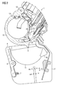
- FIG. 1 is a hearing aid 1 with audio shoe 2 shown schematically.
- the hearing aid 1 has the housing shape of a BTE device.
- the battery is disposed in a battery tray 15 in the wide, rounded end of the housing.
- the battery door 15 has a lever 5, with which it can be opened.
- the audio shoe 2 is attached to the hearing aid 1. He covers the battery door 15 together with lever 5, which are therefore shown in dashed lines. He is locked with a reaching into the hearing aid 1 retaining lug 8 and a locking component 4 on the hearing aid housing.
- FIG. 2 is a sectional view of a portion of a hearing aid 1 and a sectional view of an audio shoe 2 shown.
- the audio shoe 2 is not attached to the hearing aid 1.
- the hearing device has a pivotable about a pivot axis 12 battery drawer 15 which can be opened by means of a lever 5 and also closed again.
- the battery tray 15 is fully pivoted into the hearing aid housing.
- the hearing aid housing has an opening 20, which leads to a recess 24 within the hearing aid housing.
- the recess 24 has an arcuate concave contour. It leads to an undercut 21 in the hearing aid housing, i. to a while accessible from outside the housing, but seen from the outside behind the housing wall space within the housing.
- the region of the opening 20 opposite the undercut 21 is embodied as an abutment 22, which prevents a linear pushing movement into the undercut 21 or a straight pull movement out of the undercut 21.
- a circuit carrier 16 is arranged, which has conductor tracks and is equipped with signal processing components and other electronic components of the hearing aid 1.
- electrical contact surfaces 23 of the circuit substrate 16 are arranged. They are arranged on the inside of the hearing aid housing. As a result, they are not visible from the outside because of the abutment 22 and because of their outside arrangement in the undercut 21 and not directly accessible by a linear movement. In this respect, the contact surfaces 23 are not directly exposed to external influences.
- the audio shoe 2 has a battery charging receptacle 11 which is formed as a cavity and can receive the battery charger 15.
- a lever holder 10 is provided which can accommodate the lever 5 of the battery charger in itself.
- a locking component of the audio shoe 2 is formed by a latch 4.
- the bolt 4 is arranged on a rocker arm, which can be tilted about a tilting axis 6 and is acted upon by a spring 7.
- the spring pushes the rocker arm into the closed, locked position.
- the latch 4 is designed so that it can engage in the notch 13 on the battery charger. He has a designed as a vertical edge latch, which with the locking lug in the notch 13 cooperates. As soon as the latch 4 engages in the notch 13, the mutual latching lugs prevent a movement of the audio shoe 2 away from the hearing aid 1 (ie downwards in the illustration).
- the audio shoe 2 has a retaining lug 8.
- the retaining lug 8 is designed approximately circular arc-shaped and in particular has a circular arc-shaped surface on one side (in the figure, the long side facing the hearing aid 1).
- In the retaining lug 8 open electrical lines of the audio shoe 2, which ends on the retaining lug 8 in contact surfaces 9 and are connected thereto.
- FIG. 2 shows a sectional view of the above-described part of a hearing aid 1 and an audio shoe 2 in a different position relative to one another, namely during the attachment of the audio shoe 2 to the hearing aid 1.
- the audio shoe 2 is shown when plugging on the hearing aid 1 and with this already slightly in contact, namely on the retaining lug 8 of the audio shoe 2 and the recess 24 of the hearing aid 1.
- the retaining lug 8 For attaching namely the retaining lug 8 must first be inserted into the recess 24. Since the opening 20 leading to the recess 24 is larger than the tip of the retaining lug 8, the insertion does not require high accuracy in the movement.
- the retaining lug 8 although initially by a rectilinear movement into the recess 24 as shown can be introduced. However, further insertion is no longer possible due to the generally curved shape of the retaining lug 8 and the geometric configuration of the opening 20, the recess 24 and partially also the abutment 22 by a rectilinear movement.
- the retaining lug 8 must be rotated for further insertion by the lying in the region of the undercut 21 side of the opening 20 around (in the figure so in a clockwise direction). Such a rotational movement is supported and facilitated by the arcuate configuration of the recess 24 and the retaining lug 8. Because the concave arc shape of the recess 24 takes the convex arc shape of the recess 24 facing side of the retaining lug 8 on.
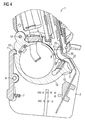
- FIG. 4 1 is a sectional view of the above-described part of a hearing aid 1 with the above-described audio shoe 2 attached using the same reference numerals, so that reference is made to the preceding description of the figures for a detailed explanation.
- the audio shoe 2 is completely attached to the hearing aid 1 by the above-explained rotational movement about the side of the opening 20 lying in the region of the undercut 21 (clockwise).
- the retaining lug 8 is thus inserted through the opening 20 and recess 24 into the undercut 21.
- the latch 4 of the audio shoe 2 is latched into the notch 13 on the battery door 15 on the opposite side of the housing.
- the engagement was made by the force of the spring 7, which has tilted the rocker arm in the corresponding direction about the tilting axis 6.
- the Beautschung with the force of the spring 7 also causes the latch 4 remains in the notch 13 and thus in the closed, locked state.
- the retaining lugs of the bolt 4 and the notch 13 cause the audio shoe 2 is not withdrawn from the hearing aid 1 when the lock is closed or can not be rotated around the side of the opening 20 located in the region of the undercut 21 (ie taken counterclockwise).
- the abutment 22 On the side of the opening 20 and holding lug 8 in turn prevents the abutment 22 that the audio shoe 2 can be removed from the hearing aid 1 away.
- the abutment 22 is intended to prevent such rectilinear removal of the audio shoe 2. From this it is clear that it is formed by an undercut 21 opposite part of the opening 20 and / or recess 24.
- FIG. 5 the audio shoe 2 is shown in perspective, the top view shows the hearing device 1 facing side of the audio shoe 2 with a trained as a battery charging receptacle 11 opening.
- the latch 4 On one side of the opening is the latch 4 and on the opposite side the retaining lug 8.
- the electrical contact surfaces 9 are arranged.
- FIG. 6 In each case a part of the hearing aid 1 and the audio shoe 2 during the Aufsteckens the audio shoe 2 is shown in perspective.
- the retaining lug 8 is inserted through the opening 20 and partially inserted into the recess 24 along the abutment 22.
- the electrical contact surfaces 9 can be seen.
- the circuit carrier 16 On the side of the hearing aid 1, the circuit carrier 16 is shown with its electrical contact surfaces 23.
- This illustration shows parts of the interior of the hearing aid housing that are not normally through the hearing aid housing to be seen; insofar as the housing is partially omitted in the illustration.
- the contact surfaces 23 are arranged in the undercut 21.
- FIG. 7 each part of the hearing aid 1 and the audio shoe 2 is shown in perspective, this time, however, already put together.
- the same reference numbers are used as in the preceding figures, so that for a detailed explanation reference is made to the preceding figure descriptions.
- the retaining lug 8 is inserted into the undercut 21.
- the contact surfaces 9 of the retaining lug 8 are connected to the contact surfaces 23 of the circuit substrate 16 in connection.
- the audio shoe 2 is both mechanically and electrically connected to the hearing aid 1.
- the invention relates to a hearing aid with audio shoe interface, an associated audio shoe, and a hearing aid system comprising a hearing aid and an audio shoe.
- a basic idea of the invention consists in a hearing aid 1 with a housing in which an undercut 21 and an abutment 22 are provided. The abutment 22 is disposed opposite the undercut 21. Undercut 21 and abutment 22 are designed such that a retaining lug 8 of an audio shoe 2 with a rotational movement in the undercut 21 is insertable. The abutment 22 is designed such that an inserted into the undercut 21 retaining lug 8 is executable only by an opposite rotational movement back from the undercut 21.
- a lock is provided by which the opposite rotational movement of a plugged audio shoe 2 is prevented.
- the undercut in the housing ensures high stability of the mechanical connection. It eliminates the need for protruding from the housing components and is therefore pleasing visually and in handling. There are no additional separate components such as axles, axle mounts, or similar. for the mechanical connection needed so that it is favorable in terms of manufacturing steps and component logistics in manufacturing. If, in addition, the electrical contacts between the audio shoe 2 and the hearing device 1 are arranged in the undercut 21, these are also optically hidden and well protected against external influences.
Landscapes
- Engineering & Computer Science (AREA)
- Physics & Mathematics (AREA)
- Health & Medical Sciences (AREA)
- General Health & Medical Sciences (AREA)
- Neurosurgery (AREA)
- Otolaryngology (AREA)
- Computer Networks & Wireless Communication (AREA)
- Acoustics & Sound (AREA)
- Signal Processing (AREA)
- Footwear And Its Accessory, Manufacturing Method And Apparatuses (AREA)
- Connector Housings Or Holding Contact Members (AREA)
- Casings For Electric Apparatus (AREA)
- Details Of Connecting Devices For Male And Female Coupling (AREA)
Applications Claiming Priority (1)
| Application Number | Priority Date | Filing Date | Title |
|---|---|---|---|
| DE102010014316A DE102010014316A1 (de) | 2010-04-09 | 2010-04-09 | Hörgerät mit Audioschuh |
Publications (2)
| Publication Number | Publication Date |
|---|---|
| EP2375783A1 true EP2375783A1 (fr) | 2011-10-12 |
| EP2375783B1 EP2375783B1 (fr) | 2017-08-30 |
Family
ID=44278944
Family Applications (1)
| Application Number | Title | Priority Date | Filing Date |
|---|---|---|---|
| EP11156702.0A Not-in-force EP2375783B1 (fr) | 2010-04-09 | 2011-03-03 | Appareil auditif doté d'un manchon audio |
Country Status (5)
| Country | Link |
|---|---|
| US (1) | US8611573B2 (fr) |
| EP (1) | EP2375783B1 (fr) |
| CN (1) | CN102215445B (fr) |
| DE (1) | DE102010014316A1 (fr) |
| DK (1) | DK2375783T3 (fr) |
Families Citing this family (1)
| Publication number | Priority date | Publication date | Assignee | Title |
|---|---|---|---|---|
| DE102013004020A1 (de) | 2013-02-28 | 2014-09-11 | Uwe Flaig | Hörhilfegerät mit Audioeingang |
Citations (8)
| Publication number | Priority date | Publication date | Assignee | Title |
|---|---|---|---|---|
| US20070047751A1 (en) | 2005-08-31 | 2007-03-01 | Markus Heerlein | Audio shoe contact for a hearing device |
| EP1838134A1 (fr) * | 2006-03-23 | 2007-09-26 | Oticon A/S | Dispositif audio de type intra-auriculaire et méthode de fixation d'un module électronique dans une cavité d'un boîtier personnalisé pour un dispositif audio de type intra-auriculaire |
| US20080192970A1 (en) | 2005-10-17 | 2008-08-14 | Widex A/S | Adapter shoe and a combination of adapter shoe and hearing aid |
| WO2008110210A1 (fr) * | 2007-03-14 | 2008-09-18 | Phonak Ag | Dispositif auditif avec une commande utilisateur |
| US20080273730A1 (en) * | 2007-05-04 | 2008-11-06 | Holger Kral | Hearing device to be worn behind an ear |
| EP2012556A1 (fr) * | 2007-07-06 | 2009-01-07 | Siemens Audiologische Technik GmbH | Procédé et agencement d'échange de données avec un appareil auditif |
| US20090022348A1 (en) | 2007-07-19 | 2009-01-22 | Siemens Medical Instruments Pte. Ltd. | Hearing apparatus with a fastening facility for attaching an audio shoe and corresponding audio shoe |
| US20090041277A1 (en) | 2007-08-10 | 2009-02-12 | Siemens Medical Instruments Pte. Ltd. | Behind-the-ear hearing aid with audio shoe which can be pushed-on linearly, and appropriate mounting method |
Family Cites Families (4)
| Publication number | Priority date | Publication date | Assignee | Title |
|---|---|---|---|---|
| DK42197A (da) * | 1997-04-15 | 1998-10-16 | Toepholm & Westermann | Kompakt moduleret i-øret høreapparat |
| AU2003218954B2 (en) * | 2003-03-06 | 2008-02-14 | Widex A/S | Method of connecting an accessory to a hearing aid and the combination of an adapter and an accessory |
| DE102004035256B3 (de) | 2004-07-21 | 2005-09-22 | Siemens Audiologische Technik Gmbh | Hörhilfegerätesystem sowie Verfahren zum Betrieb eines Hörhilfegerätesystems bei Audio-Empfang |
| DE102005032273B8 (de) * | 2005-07-11 | 2009-08-13 | Siemens Audiologische Technik Gmbh | Hörgerätesystem, Hörgerät und entsprechendes Verfahren zu dessen Einstellung |
-
2010
- 2010-04-09 DE DE102010014316A patent/DE102010014316A1/de not_active Ceased
-
2011
- 2011-03-03 DK DK11156702.0T patent/DK2375783T3/da active
- 2011-03-03 EP EP11156702.0A patent/EP2375783B1/fr not_active Not-in-force
- 2011-04-08 CN CN201110087606.XA patent/CN102215445B/zh not_active Expired - Fee Related
- 2011-04-11 US US13/083,713 patent/US8611573B2/en not_active Expired - Fee Related
Patent Citations (8)
| Publication number | Priority date | Publication date | Assignee | Title |
|---|---|---|---|---|
| US20070047751A1 (en) | 2005-08-31 | 2007-03-01 | Markus Heerlein | Audio shoe contact for a hearing device |
| US20080192970A1 (en) | 2005-10-17 | 2008-08-14 | Widex A/S | Adapter shoe and a combination of adapter shoe and hearing aid |
| EP1838134A1 (fr) * | 2006-03-23 | 2007-09-26 | Oticon A/S | Dispositif audio de type intra-auriculaire et méthode de fixation d'un module électronique dans une cavité d'un boîtier personnalisé pour un dispositif audio de type intra-auriculaire |
| WO2008110210A1 (fr) * | 2007-03-14 | 2008-09-18 | Phonak Ag | Dispositif auditif avec une commande utilisateur |
| US20080273730A1 (en) * | 2007-05-04 | 2008-11-06 | Holger Kral | Hearing device to be worn behind an ear |
| EP2012556A1 (fr) * | 2007-07-06 | 2009-01-07 | Siemens Audiologische Technik GmbH | Procédé et agencement d'échange de données avec un appareil auditif |
| US20090022348A1 (en) | 2007-07-19 | 2009-01-22 | Siemens Medical Instruments Pte. Ltd. | Hearing apparatus with a fastening facility for attaching an audio shoe and corresponding audio shoe |
| US20090041277A1 (en) | 2007-08-10 | 2009-02-12 | Siemens Medical Instruments Pte. Ltd. | Behind-the-ear hearing aid with audio shoe which can be pushed-on linearly, and appropriate mounting method |
Also Published As
| Publication number | Publication date |
|---|---|
| CN102215445B (zh) | 2015-11-18 |
| DE102010014316A1 (de) | 2011-10-13 |
| US20110249848A1 (en) | 2011-10-13 |
| US8611573B2 (en) | 2013-12-17 |
| DK2375783T3 (da) | 2017-12-04 |
| CN102215445A (zh) | 2011-10-12 |
| EP2375783B1 (fr) | 2017-08-30 |
Similar Documents
| Publication | Publication Date | Title |
|---|---|---|
| EP2540098B1 (fr) | Connecteur pour appareil auditif ric-bte et appareil auditif ric-bte | |
| EP0591791B1 (fr) | Prothèse auditive programmable | |
| DE60204241T2 (de) | Verfahren zur herstellung eines hörgeräts | |
| EP1183910A1 (fr) | Appareil auditif se pla ant derriere l'oreille et module rapporte pour un tel appareil auditif | |
| EP1921894A2 (fr) | Appareil de chargement pour un appareil auditif | |
| EP2034768A2 (fr) | Appareil auditif doté d'un moyen de contact, unité externe correspondante et dispositif de charge de batterie | |
| WO2019105949A1 (fr) | Appareil auditif modulaire | |
| EP0254925A1 (fr) | Prothèse auditive avec disposition à lame de contact | |
| EP2026609B1 (fr) | Appareil auditif derrière l'oreille doté d'un manchon audio linéaire accolable et procédé de montage correspondant | |
| DE2219970A1 (de) | Elektrisches hoerhilfegeraet | |
| EP2884771A1 (fr) | Appareil auditif de contour d'oreille doté d'un boîtier et de crochet support | |
| EP2144456A1 (fr) | Aide auditive dotée d'un compartiment de batterie verrouillable | |
| EP2375783B1 (fr) | Appareil auditif doté d'un manchon audio | |
| EP2222094B1 (fr) | Boîtier pour appareil auditif avec élément de sécurisation | |
| EP2592849B1 (fr) | Prothèse auditive avec un compartiment pour batterie | |
| DE102023133923A1 (de) | Steckverbindermodul für einen modularen Industriesteckverbinder | |
| CH668154A5 (en) | Hearing aid with electroacoustic transducer - fits behind ear and has facility for plugging in range of operational mode elements | |
| DE102012204185B3 (de) | Hörinstrument-Batterielade mit Verriegelung | |
| EP3419312B1 (fr) | Appareil auditif | |
| EP4096243B1 (fr) | Dispositif auditif | |
| DE9306204U1 (de) | Adapter und dazu in technisch-funktionellem Zusammenhang stehendes Hörhilfegerät | |
| DE8808169U1 (de) | Audio-Schuh für Hörgeräte | |
| DE3624568A1 (de) | Hoergeraet mit einer herausschwenkbaren batterielade | |
| DE102008050569B4 (de) | Batterielade oder Batterietür mit Verschlussvorrichtung für ein Hörgerät | |
| DE8317845U1 (de) | Hoergeraet |
Legal Events
| Date | Code | Title | Description |
|---|---|---|---|
| PUAI | Public reference made under article 153(3) epc to a published international application that has entered the european phase |
Free format text: ORIGINAL CODE: 0009012 |
|
| AK | Designated contracting states |
Kind code of ref document: A1 Designated state(s): AL AT BE BG CH CY CZ DE DK EE ES FI FR GB GR HR HU IE IS IT LI LT LU LV MC MK MT NL NO PL PT RO RS SE SI SK SM TR |
|
| AX | Request for extension of the european patent |
Extension state: BA ME |
|
| 17P | Request for examination filed |
Effective date: 20120417 |
|
| RAP1 | Party data changed (applicant data changed or rights of an application transferred) |
Owner name: SIVANTOS PTE. LTD. |
|
| GRAP | Despatch of communication of intention to grant a patent |
Free format text: ORIGINAL CODE: EPIDOSNIGR1 |
|
| STAA | Information on the status of an ep patent application or granted ep patent |
Free format text: STATUS: GRANT OF PATENT IS INTENDED |
|
| INTG | Intention to grant announced |
Effective date: 20170214 |
|
| GRAJ | Information related to disapproval of communication of intention to grant by the applicant or resumption of examination proceedings by the epo deleted |
Free format text: ORIGINAL CODE: EPIDOSDIGR1 |
|
| STAA | Information on the status of an ep patent application or granted ep patent |
Free format text: STATUS: REQUEST FOR EXAMINATION WAS MADE |
|
| GRAP | Despatch of communication of intention to grant a patent |
Free format text: ORIGINAL CODE: EPIDOSNIGR1 |
|
| STAA | Information on the status of an ep patent application or granted ep patent |
Free format text: STATUS: GRANT OF PATENT IS INTENDED |
|
| INTC | Intention to grant announced (deleted) | ||
| GRAS | Grant fee paid |
Free format text: ORIGINAL CODE: EPIDOSNIGR3 |
|
| INTG | Intention to grant announced |
Effective date: 20170626 |
|
| GRAA | (expected) grant |
Free format text: ORIGINAL CODE: 0009210 |
|
| STAA | Information on the status of an ep patent application or granted ep patent |
Free format text: STATUS: THE PATENT HAS BEEN GRANTED |
|
| AK | Designated contracting states |
Kind code of ref document: B1 Designated state(s): AL AT BE BG CH CY CZ DE DK EE ES FI FR GB GR HR HU IE IS IT LI LT LU LV MC MK MT NL NO PL PT RO RS SE SI SK SM TR |
|
| REG | Reference to a national code |
Ref country code: GB Ref legal event code: FG4D Free format text: NOT ENGLISH |
|
| REG | Reference to a national code |
Ref country code: CH Ref legal event code: EP |
|
| REG | Reference to a national code |
Ref country code: CH Ref legal event code: NV Representative=s name: E. BLUM AND CO. AG PATENT- UND MARKENANWAELTE , CH Ref country code: AT Ref legal event code: REF Ref document number: 924694 Country of ref document: AT Kind code of ref document: T Effective date: 20170915 |
|
| REG | Reference to a national code |
Ref country code: IE Ref legal event code: FG4D Free format text: LANGUAGE OF EP DOCUMENT: GERMAN |
|
| REG | Reference to a national code |
Ref country code: DE Ref legal event code: R096 Ref document number: 502011012883 Country of ref document: DE |
|
| REG | Reference to a national code |
Ref country code: DK Ref legal event code: T3 Effective date: 20171127 |
|
| REG | Reference to a national code |
Ref country code: NL Ref legal event code: MP Effective date: 20170830 |
|
| REG | Reference to a national code |
Ref country code: LT Ref legal event code: MG4D |
|
| PG25 | Lapsed in a contracting state [announced via postgrant information from national office to epo] |
Ref country code: FI Free format text: LAPSE BECAUSE OF FAILURE TO SUBMIT A TRANSLATION OF THE DESCRIPTION OR TO PAY THE FEE WITHIN THE PRESCRIBED TIME-LIMIT Effective date: 20170830 Ref country code: SE Free format text: LAPSE BECAUSE OF FAILURE TO SUBMIT A TRANSLATION OF THE DESCRIPTION OR TO PAY THE FEE WITHIN THE PRESCRIBED TIME-LIMIT Effective date: 20170830 Ref country code: LT Free format text: LAPSE BECAUSE OF FAILURE TO SUBMIT A TRANSLATION OF THE DESCRIPTION OR TO PAY THE FEE WITHIN THE PRESCRIBED TIME-LIMIT Effective date: 20170830 Ref country code: NO Free format text: LAPSE BECAUSE OF FAILURE TO SUBMIT A TRANSLATION OF THE DESCRIPTION OR TO PAY THE FEE WITHIN THE PRESCRIBED TIME-LIMIT Effective date: 20171130 Ref country code: HR Free format text: LAPSE BECAUSE OF FAILURE TO SUBMIT A TRANSLATION OF THE DESCRIPTION OR TO PAY THE FEE WITHIN THE PRESCRIBED TIME-LIMIT Effective date: 20170830 |
|
| RAP2 | Party data changed (patent owner data changed or rights of a patent transferred) |
Owner name: SIVANTOS PTE. LTD. |
|
| PG25 | Lapsed in a contracting state [announced via postgrant information from national office to epo] |
Ref country code: ES Free format text: LAPSE BECAUSE OF FAILURE TO SUBMIT A TRANSLATION OF THE DESCRIPTION OR TO PAY THE FEE WITHIN THE PRESCRIBED TIME-LIMIT Effective date: 20170830 Ref country code: BG Free format text: LAPSE BECAUSE OF FAILURE TO SUBMIT A TRANSLATION OF THE DESCRIPTION OR TO PAY THE FEE WITHIN THE PRESCRIBED TIME-LIMIT Effective date: 20171130 Ref country code: IS Free format text: LAPSE BECAUSE OF FAILURE TO SUBMIT A TRANSLATION OF THE DESCRIPTION OR TO PAY THE FEE WITHIN THE PRESCRIBED TIME-LIMIT Effective date: 20171230 Ref country code: LV Free format text: LAPSE BECAUSE OF FAILURE TO SUBMIT A TRANSLATION OF THE DESCRIPTION OR TO PAY THE FEE WITHIN THE PRESCRIBED TIME-LIMIT Effective date: 20170830 Ref country code: GR Free format text: LAPSE BECAUSE OF FAILURE TO SUBMIT A TRANSLATION OF THE DESCRIPTION OR TO PAY THE FEE WITHIN THE PRESCRIBED TIME-LIMIT Effective date: 20171201 Ref country code: RS Free format text: LAPSE BECAUSE OF FAILURE TO SUBMIT A TRANSLATION OF THE DESCRIPTION OR TO PAY THE FEE WITHIN THE PRESCRIBED TIME-LIMIT Effective date: 20170830 |
|
| REG | Reference to a national code |
Ref country code: FR Ref legal event code: PLFP Year of fee payment: 8 |
|
| PG25 | Lapsed in a contracting state [announced via postgrant information from national office to epo] |
Ref country code: NL Free format text: LAPSE BECAUSE OF FAILURE TO SUBMIT A TRANSLATION OF THE DESCRIPTION OR TO PAY THE FEE WITHIN THE PRESCRIBED TIME-LIMIT Effective date: 20170830 |
|
| PG25 | Lapsed in a contracting state [announced via postgrant information from national office to epo] |
Ref country code: PL Free format text: LAPSE BECAUSE OF FAILURE TO SUBMIT A TRANSLATION OF THE DESCRIPTION OR TO PAY THE FEE WITHIN THE PRESCRIBED TIME-LIMIT Effective date: 20170830 Ref country code: CZ Free format text: LAPSE BECAUSE OF FAILURE TO SUBMIT A TRANSLATION OF THE DESCRIPTION OR TO PAY THE FEE WITHIN THE PRESCRIBED TIME-LIMIT Effective date: 20170830 Ref country code: RO Free format text: LAPSE BECAUSE OF FAILURE TO SUBMIT A TRANSLATION OF THE DESCRIPTION OR TO PAY THE FEE WITHIN THE PRESCRIBED TIME-LIMIT Effective date: 20170830 |
|
| PG25 | Lapsed in a contracting state [announced via postgrant information from national office to epo] |
Ref country code: SM Free format text: LAPSE BECAUSE OF FAILURE TO SUBMIT A TRANSLATION OF THE DESCRIPTION OR TO PAY THE FEE WITHIN THE PRESCRIBED TIME-LIMIT Effective date: 20170830 Ref country code: SK Free format text: LAPSE BECAUSE OF FAILURE TO SUBMIT A TRANSLATION OF THE DESCRIPTION OR TO PAY THE FEE WITHIN THE PRESCRIBED TIME-LIMIT Effective date: 20170830 Ref country code: EE Free format text: LAPSE BECAUSE OF FAILURE TO SUBMIT A TRANSLATION OF THE DESCRIPTION OR TO PAY THE FEE WITHIN THE PRESCRIBED TIME-LIMIT Effective date: 20170830 Ref country code: IT Free format text: LAPSE BECAUSE OF FAILURE TO SUBMIT A TRANSLATION OF THE DESCRIPTION OR TO PAY THE FEE WITHIN THE PRESCRIBED TIME-LIMIT Effective date: 20170830 |
|
| REG | Reference to a national code |
Ref country code: DE Ref legal event code: R097 Ref document number: 502011012883 Country of ref document: DE |
|
| PLBE | No opposition filed within time limit |
Free format text: ORIGINAL CODE: 0009261 |
|
| STAA | Information on the status of an ep patent application or granted ep patent |
Free format text: STATUS: NO OPPOSITION FILED WITHIN TIME LIMIT |
|
| 26N | No opposition filed |
Effective date: 20180531 |
|
| PG25 | Lapsed in a contracting state [announced via postgrant information from national office to epo] |
Ref country code: SI Free format text: LAPSE BECAUSE OF FAILURE TO SUBMIT A TRANSLATION OF THE DESCRIPTION OR TO PAY THE FEE WITHIN THE PRESCRIBED TIME-LIMIT Effective date: 20170830 |
|
| PG25 | Lapsed in a contracting state [announced via postgrant information from national office to epo] |
Ref country code: MT Free format text: LAPSE BECAUSE OF FAILURE TO SUBMIT A TRANSLATION OF THE DESCRIPTION OR TO PAY THE FEE WITHIN THE PRESCRIBED TIME-LIMIT Effective date: 20170830 |
|
| PG25 | Lapsed in a contracting state [announced via postgrant information from national office to epo] |
Ref country code: MC Free format text: LAPSE BECAUSE OF FAILURE TO SUBMIT A TRANSLATION OF THE DESCRIPTION OR TO PAY THE FEE WITHIN THE PRESCRIBED TIME-LIMIT Effective date: 20170830 |
|
| REG | Reference to a national code |
Ref country code: BE Ref legal event code: MM Effective date: 20180331 |
|
| REG | Reference to a national code |
Ref country code: IE Ref legal event code: MM4A |
|
| PG25 | Lapsed in a contracting state [announced via postgrant information from national office to epo] |
Ref country code: LU Free format text: LAPSE BECAUSE OF NON-PAYMENT OF DUE FEES Effective date: 20180303 |
|
| PG25 | Lapsed in a contracting state [announced via postgrant information from national office to epo] |
Ref country code: IE Free format text: LAPSE BECAUSE OF NON-PAYMENT OF DUE FEES Effective date: 20180303 |
|
| PG25 | Lapsed in a contracting state [announced via postgrant information from national office to epo] |
Ref country code: BE Free format text: LAPSE BECAUSE OF NON-PAYMENT OF DUE FEES Effective date: 20180331 |
|
| PGFP | Annual fee paid to national office [announced via postgrant information from national office to epo] |
Ref country code: DE Payment date: 20190325 Year of fee payment: 9 Ref country code: FR Payment date: 20190326 Year of fee payment: 9 Ref country code: GB Payment date: 20190325 Year of fee payment: 9 Ref country code: CH Payment date: 20190325 Year of fee payment: 9 |
|
| REG | Reference to a national code |
Ref country code: AT Ref legal event code: MM01 Ref document number: 924694 Country of ref document: AT Kind code of ref document: T Effective date: 20180303 |
|
| PGFP | Annual fee paid to national office [announced via postgrant information from national office to epo] |
Ref country code: DK Payment date: 20190325 Year of fee payment: 9 |
|
| PG25 | Lapsed in a contracting state [announced via postgrant information from national office to epo] |
Ref country code: AT Free format text: LAPSE BECAUSE OF NON-PAYMENT OF DUE FEES Effective date: 20180303 |
|
| PG25 | Lapsed in a contracting state [announced via postgrant information from national office to epo] |
Ref country code: TR Free format text: LAPSE BECAUSE OF FAILURE TO SUBMIT A TRANSLATION OF THE DESCRIPTION OR TO PAY THE FEE WITHIN THE PRESCRIBED TIME-LIMIT Effective date: 20170830 |
|
| PG25 | Lapsed in a contracting state [announced via postgrant information from national office to epo] |
Ref country code: HU Free format text: LAPSE BECAUSE OF FAILURE TO SUBMIT A TRANSLATION OF THE DESCRIPTION OR TO PAY THE FEE WITHIN THE PRESCRIBED TIME-LIMIT; INVALID AB INITIO Effective date: 20110303 Ref country code: PT Free format text: LAPSE BECAUSE OF FAILURE TO SUBMIT A TRANSLATION OF THE DESCRIPTION OR TO PAY THE FEE WITHIN THE PRESCRIBED TIME-LIMIT Effective date: 20170830 |
|
| PG25 | Lapsed in a contracting state [announced via postgrant information from national office to epo] |
Ref country code: CY Free format text: LAPSE BECAUSE OF FAILURE TO SUBMIT A TRANSLATION OF THE DESCRIPTION OR TO PAY THE FEE WITHIN THE PRESCRIBED TIME-LIMIT Effective date: 20170830 Ref country code: MK Free format text: LAPSE BECAUSE OF NON-PAYMENT OF DUE FEES Effective date: 20170830 |
|
| PG25 | Lapsed in a contracting state [announced via postgrant information from national office to epo] |
Ref country code: AL Free format text: LAPSE BECAUSE OF FAILURE TO SUBMIT A TRANSLATION OF THE DESCRIPTION OR TO PAY THE FEE WITHIN THE PRESCRIBED TIME-LIMIT Effective date: 20170830 |
|
| REG | Reference to a national code |
Ref country code: DE Ref legal event code: R119 Ref document number: 502011012883 Country of ref document: DE |
|
| REG | Reference to a national code |
Ref country code: CH Ref legal event code: PL |
|
| REG | Reference to a national code |
Ref country code: DK Ref legal event code: EBP Effective date: 20200331 |
|
| PG25 | Lapsed in a contracting state [announced via postgrant information from national office to epo] |
Ref country code: LI Free format text: LAPSE BECAUSE OF NON-PAYMENT OF DUE FEES Effective date: 20200331 Ref country code: FR Free format text: LAPSE BECAUSE OF NON-PAYMENT OF DUE FEES Effective date: 20200331 Ref country code: DE Free format text: LAPSE BECAUSE OF NON-PAYMENT OF DUE FEES Effective date: 20201001 Ref country code: CH Free format text: LAPSE BECAUSE OF NON-PAYMENT OF DUE FEES Effective date: 20200331 |
|
| GBPC | Gb: european patent ceased through non-payment of renewal fee |
Effective date: 20200303 |
|
| PG25 | Lapsed in a contracting state [announced via postgrant information from national office to epo] |
Ref country code: GB Free format text: LAPSE BECAUSE OF NON-PAYMENT OF DUE FEES Effective date: 20200303 Ref country code: DK Free format text: LAPSE BECAUSE OF NON-PAYMENT OF DUE FEES Effective date: 20200331 |