EP2376784B1 - Procédé de commande d'une installation de compresseurs - Google Patents
Procédé de commande d'une installation de compresseurs Download PDFInfo
- Publication number
- EP2376784B1 EP2376784B1 EP09799640.9A EP09799640A EP2376784B1 EP 2376784 B1 EP2376784 B1 EP 2376784B1 EP 09799640 A EP09799640 A EP 09799640A EP 2376784 B1 EP2376784 B1 EP 2376784B1
- Authority
- EP
- European Patent Office
- Prior art keywords
- pressure
- switching
- compressors
- pressurized fluid
- compressor
- Prior art date
- Legal status (The legal status is an assumption and is not a legal conclusion. Google has not performed a legal analysis and makes no representation as to the accuracy of the status listed.)
- Revoked
Links
Images

Classifications
-
- F—MECHANICAL ENGINEERING; LIGHTING; HEATING; WEAPONS; BLASTING
- F04—POSITIVE - DISPLACEMENT MACHINES FOR LIQUIDS; PUMPS FOR LIQUIDS OR ELASTIC FLUIDS
- F04B—POSITIVE-DISPLACEMENT MACHINES FOR LIQUIDS; PUMPS
- F04B49/00—Control, e.g. of pump delivery, or pump pressure of, or safety measures for, machines, pumps, or pumping installations, not otherwise provided for, or of interest apart from, groups F04B1/00 - F04B47/00
- F04B49/08—Regulating by delivery pressure
-
- F—MECHANICAL ENGINEERING; LIGHTING; HEATING; WEAPONS; BLASTING
- F04—POSITIVE - DISPLACEMENT MACHINES FOR LIQUIDS; PUMPS FOR LIQUIDS OR ELASTIC FLUIDS
- F04B—POSITIVE-DISPLACEMENT MACHINES FOR LIQUIDS; PUMPS
- F04B49/00—Control, e.g. of pump delivery, or pump pressure of, or safety measures for, machines, pumps, or pumping installations, not otherwise provided for, or of interest apart from, groups F04B1/00 - F04B47/00
- F04B49/007—Installations or systems with two or more pumps or pump cylinders, wherein the flow-path through the stages can be changed, e.g. from series to parallel
-
- F—MECHANICAL ENGINEERING; LIGHTING; HEATING; WEAPONS; BLASTING
- F04—POSITIVE - DISPLACEMENT MACHINES FOR LIQUIDS; PUMPS FOR LIQUIDS OR ELASTIC FLUIDS
- F04B—POSITIVE-DISPLACEMENT MACHINES FOR LIQUIDS; PUMPS
- F04B49/00—Control, e.g. of pump delivery, or pump pressure of, or safety measures for, machines, pumps, or pumping installations, not otherwise provided for, or of interest apart from, groups F04B1/00 - F04B47/00
- F04B49/06—Control using electricity
- F04B49/065—Control using electricity and making use of computers
-
- F—MECHANICAL ENGINEERING; LIGHTING; HEATING; WEAPONS; BLASTING
- F04—POSITIVE - DISPLACEMENT MACHINES FOR LIQUIDS; PUMPS FOR LIQUIDS OR ELASTIC FLUIDS
- F04C—ROTARY-PISTON, OR OSCILLATING-PISTON, POSITIVE-DISPLACEMENT MACHINES FOR LIQUIDS; ROTARY-PISTON, OR OSCILLATING-PISTON, POSITIVE-DISPLACEMENT PUMPS
- F04C28/00—Control of, monitoring of, or safety arrangements for, pumps or pumping installations specially adapted for elastic fluids
- F04C28/02—Control of, monitoring of, or safety arrangements for, pumps or pumping installations specially adapted for elastic fluids specially adapted for several pumps connected in series or in parallel
-
- F—MECHANICAL ENGINEERING; LIGHTING; HEATING; WEAPONS; BLASTING
- F04—POSITIVE - DISPLACEMENT MACHINES FOR LIQUIDS; PUMPS FOR LIQUIDS OR ELASTIC FLUIDS
- F04C—ROTARY-PISTON, OR OSCILLATING-PISTON, POSITIVE-DISPLACEMENT MACHINES FOR LIQUIDS; ROTARY-PISTON, OR OSCILLATING-PISTON, POSITIVE-DISPLACEMENT PUMPS
- F04C28/00—Control of, monitoring of, or safety arrangements for, pumps or pumping installations specially adapted for elastic fluids
- F04C28/24—Control of, monitoring of, or safety arrangements for, pumps or pumping installations specially adapted for elastic fluids characterised by using valves controlling pressure or flow rate, e.g. discharge valves or unloading valves
-
- F—MECHANICAL ENGINEERING; LIGHTING; HEATING; WEAPONS; BLASTING
- F04—POSITIVE - DISPLACEMENT MACHINES FOR LIQUIDS; PUMPS FOR LIQUIDS OR ELASTIC FLUIDS
- F04D—NON-POSITIVE-DISPLACEMENT PUMPS
- F04D27/00—Control, e.g. regulation, of pumps, pumping installations or pumping systems specially adapted for elastic fluids
- F04D27/005—Control, e.g. regulation, of pumps, pumping installations or pumping systems specially adapted for elastic fluids by changing flow path between different stages or between a plurality of compressors; Load distribution between compressors
-
- G—PHYSICS
- G05—CONTROLLING; REGULATING
- G05D—SYSTEMS FOR CONTROLLING OR REGULATING NON-ELECTRIC VARIABLES
- G05D7/00—Control of flow
- G05D7/06—Control of flow characterised by the use of electric means
- G05D7/0617—Control of flow characterised by the use of electric means specially adapted for fluid materials
- G05D7/0629—Control of flow characterised by the use of electric means specially adapted for fluid materials characterised by the type of regulator means
-
- F—MECHANICAL ENGINEERING; LIGHTING; HEATING; WEAPONS; BLASTING
- F04—POSITIVE - DISPLACEMENT MACHINES FOR LIQUIDS; PUMPS FOR LIQUIDS OR ELASTIC FLUIDS
- F04C—ROTARY-PISTON, OR OSCILLATING-PISTON, POSITIVE-DISPLACEMENT MACHINES FOR LIQUIDS; ROTARY-PISTON, OR OSCILLATING-PISTON, POSITIVE-DISPLACEMENT PUMPS
- F04C2270/00—Control; Monitoring or safety arrangements
- F04C2270/18—Pressure
- F04C2270/185—Controlled or regulated
-
- F—MECHANICAL ENGINEERING; LIGHTING; HEATING; WEAPONS; BLASTING
- F04—POSITIVE - DISPLACEMENT MACHINES FOR LIQUIDS; PUMPS FOR LIQUIDS OR ELASTIC FLUIDS
- F04C—ROTARY-PISTON, OR OSCILLATING-PISTON, POSITIVE-DISPLACEMENT MACHINES FOR LIQUIDS; ROTARY-PISTON, OR OSCILLATING-PISTON, POSITIVE-DISPLACEMENT PUMPS
- F04C2270/00—Control; Monitoring or safety arrangements
- F04C2270/56—Number of pump/machine units in operation
-
- F—MECHANICAL ENGINEERING; LIGHTING; HEATING; WEAPONS; BLASTING
- F04—POSITIVE - DISPLACEMENT MACHINES FOR LIQUIDS; PUMPS FOR LIQUIDS OR ELASTIC FLUIDS
- F04C—ROTARY-PISTON, OR OSCILLATING-PISTON, POSITIVE-DISPLACEMENT MACHINES FOR LIQUIDS; ROTARY-PISTON, OR OSCILLATING-PISTON, POSITIVE-DISPLACEMENT PUMPS
- F04C23/00—Combinations of two or more pumps, each being of rotary-piston or oscillating-piston type, specially adapted for elastic fluids; Pumping installations specially adapted for elastic fluids; Multi-stage pumps specially adapted for elastic fluids
- F04C23/001—Combinations of two or more pumps, each being of rotary-piston or oscillating-piston type, specially adapted for elastic fluids; Pumping installations specially adapted for elastic fluids; Multi-stage pumps specially adapted for elastic fluids of similar working principle
Definitions
- the invention relates to a method for controlling a compressor system comprising a plurality of compressors, in particular of different design and / or performance. At the same time, the invention relates to a control device for such a compressor system.
- a compressor system with a control method is from the documents WO03 / 095841 A1 and EP 0 431 287 A1 known.
- Compressor plants especially compressor systems intended for industrial applications, typically require a large number of individual compressors to supply this pressurized fluid to provide sufficient pressurized fluid.
- the cost-effectiveness of the individual components and the entire compressor system is increasingly taken into account not only in the design and planning of the compressor system, but also in their operation.
- These aspects concerning the economics of the compressor system are typically taken into account along with environmental regulations or quality requirements that must also be complied with.
- the energy consumption of a compressor installation can account for up to 80% of the total operating costs, which is why the energy requirement counts as the main cost factor for a compressor installation operator.
- a control of the compressor system allows about the appropriate division of operating times of different compressors and thus reduces the risk of failure or facilitates the maintenance of the compressor system.
- failure of a compressor for example, further located in idle or at a standstill compressors can be addressed by the controller or regulation and caused to provide pressurized fluid to prevent the decrease in the operating pressure of the compressor system or its stoppage.
- cascade or pressure band controls are used to control compressor systems comprising a plurality of compressors, which decide Which compressor of the compressor system is switched on or off under predetermined operating conditions.
- each compressor is assigned a specific pressure range, according to which the connection or disconnection of a respective compressor is determined by the controller.
- the demanded quantity of pressurized fluid can be covered by connecting a larger number of compressors or by connecting compressors with an increased delivery quantity of pressurized fluid compared to the other.
- a disadvantage of such regulations is that typically no consideration is given to a current pressure fluid consumption or the change in the current pressure fluid removal.
- Advanced tape controls make it possible to control any number of compressors through a single print belt.
- Such a control method on the one hand, the reduction of the maximum prevailing in the compressor system pressure of pressurized fluid can be achieved, and at the same time some energy losses are reduced in the compressor system.
- pressure belt controls in a typical gradation of individual compressors to each other in fluctuating removal of pressurized fluid from the compressor system are not suitable to control a compressor system so that the pressure fluid demand can be sufficiently covered on the one hand and on the other hand in an energetically efficient manner.
- operating conditions or constellations can occur in the compressor system, which either lead to an insufficient supply of pressurized fluid or an extremely inefficient supply of pressurized fluid.
- this known from the prior art disadvantages therefore, has the task of proposing an improved method for controlling a compressor system, which allows a sufficient supply of pressure fluid even with fluctuating removal of pressurized fluid from the compressor system, at the same time as possible caused by the control switching operations economically.
- this object is achieved by a method for controlling a compressor system, which comprises a plurality of compressors, in particular of different design and / or performance, according to claim 1. Moreover, the object is achieved by a control device for such a compressor system according to claim 15.
- the object underlying the invention is achieved by a method for controlling a compressor system comprising a plurality of compressors, in particular of different design and / or performance, wherein despite the possibly also fluctuating removal of pressurized fluid from the pressurized fluid system by the compressor unit in a pressurized fluid system a predetermined overpressure is to be maintained, wherein at fixed or variable intervals decisions are made on switching operations for adapting the system to current conditions, wherein excluded in a preselection step, taking into account the current conditions, switching alternatives from the plurality of combinatorially available switching alternatives, wherein in a main selection step, remaining switching alternatives are weighed against one another using one or more optimization criteria and the optimal scarf under the given criteria is selected and in a control step, the selected switching alternative for implementation in the compressor system is output.
- measures to increase the generation of compressed pressure fluid and upon reaching a shutdown pressure measures to reduce the generation of compressed pressure fluid are taken from the control of the system upon reaching a possibly variable Zuschaltdruck, the cut-off pressure is variable and depending on the current configuration of the compressor system and / or in consideration of a specified switching action (a fixed change in the configuration of the compressor system) is variable.
- the maintenance of a predetermined overpressure should be such that a predetermined, not to be reached by the real pressure curve adaptation pressure through the real pressure curve is not or only insignificantly and / or short, and optionally not an upper pressure limit or only slightly and / or or briefly exceeded.
- a control device for a compressor system which comprises a plurality of compressors, in particular different design and / or performance, which is to be maintained by the compressor unit in a pressurized fluid system despite possibly also fluctuating removal of pressurized fluid from the pressurized fluid system, a predetermined pressure in which, at fixed or variable intervals, decisions are made about switching operations for adapting the system to current conditions
- the control device comprises: an exclusion device which, taking into account the current conditions, Excludes switching alternatives from the plurality of combinatorially available switching alternatives, a selection device that balances the remaining switching alternatives against one another using one or more optimization criteria and selects an optimal switching alternative from the predetermined criteria, and an output device that is used to output the selected switching alternative for implementation in the Compressor system is formed.
- control device may further include: shutdown pressure determining means which, in the event of overproduction of pressurized fluid, determines a shutdown pressure as a function of the current configuration of the compressor system and / or taking into account a predetermined switching action (a predetermined change in the configuration of the compressor system).
- control should also be understood in the sense of a regulation. Since the method for controlling a compressor system and the individual embodiments of the method can have both control-specific and control-specific features, in the present case a stringent distinction between the two terms has been dispensed with in favor of comprehensible readability.
- a core idea of the present invention is that prior to the implementation of a switching operation for adaptation of the pressurized fluid system to current conditions, a plurality of possible switching alternatives is taken into consideration, which are weighed against one another using one or more optimization criteria in order to select a switching alternative that is as optimal as possible for implementation can.
- numerous possible switching alternatives can be excluded prior to carrying out the main selection step, whereby subsequently only a smaller number of possible switching alternatives have to be compared with each other.
- This separation of different selection steps allows a relatively rapid selection of the best possible switching alternative, which is then output in a control step via a switching command for implementation in the compressor system.
- control of the compressor system upon reaching a cut-off pressure measures to reduce the generation of compressed pressure fluid, wherein the cut-off pressure is variable. Accordingly, the control developed in this way differs from a typical pressure band control known from the prior art, in which switching operations are usually triggered when fixed predetermined pressure values are reached.
- the variable design of the cut-off pressure allows a suitable adaptation of a parking action to the current configuration of the compressor system or can also take into account predetermined parking operations, according to a fixed change in the configuration of the compressor system.
- connection pressure should be understood to mean a virtual pressure value, upon reaching which switching operations are initiated by the controller of the compressor system for the purpose of counteracting a drop in the overpressure prevailing in the pressure fluid system.
- the additional pressure is therefore below the cut-off pressure, which is also defined as a virtual pressure value, at which, when the real pressure curve increases, switching operations are also initiated in the compressor system which result in a shutdown of compressors.
- Switching on as well as switching off compressors may involve not only switching the entire compressor unit on or off in a load run or idle, but also gradually changing the flow rate to larger ones or smaller values.
- a changing course of the pressure prevailing in the compressor system results.
- This pressure profile which represents a real measurable variable, has in the course of its time local minimum and local maximum values, which results from the removal of pressurized fluid from the pressurized fluid system, or the provision of pressurized fluid through the respective compressors.
- Typical switching operations to be performed when the cut-off pressure is exceeded are switching a compressor or a compressor group from load to idle or even reducing the mileage of load-traveling compressors or groups of compressors.
- Typical switching operations, which are to be implemented when falling below the lower than the cut-off pressure in the compressor system are the load circuit of a standstill or idle compressor or increase the mileage of load-running compressors or compressor groups to achieve the increased promotion of pressurized fluid ,
- switching operations are essentially immediately implemented when the cut-off pressure is exceeded.
- Switching operations which are performed at a decreasing in the compressor system and the Zuschalttik underschreitenden overpressure, but typically only with a certain time delay (dead time) implemented as about a start of a compressor from standstill or idle to the desired operating speed of a technically necessary Forward flow required. Accordingly, such lead times when switching off a compressor compared to a switching of a compressor are lower, however, both switching operations lead to a typically staggered implementation of the induced switching operations.
- the virtual cut-off pressure in practice is substantially identical to a local maximum value of the real pressure curve to be achieved. Exceptions in the case of very rapid reductions in the pressure fluid requirement and / or faulty selection too small compressors to be switched except load are possible, but rarely encountered in practice.
- the virtual Zuschalttik is usually well above the reachable virtual adaptation pressure, which is to correspond to the minimum value of the real pressure curve, as falling below the Zuschaltbuches the implementation of Zuschalttmaschineen is caused, but these only delayed in time due to the compressors immanent delay times with the full pressure fluid delivery can start.
- One aim of the method of controlling a compressor system developed further in accordance with a preferred embodiment is to determine the connection pressure such that the minimum values of the real pressure profile reach the adaptation pressure as precisely as possible, but not below it.
- the adaptation pressure is a virtual pressure value which the minimum values of the real pressure curve should reach as precisely as possible.
- the adaptation pressure is thus a default value for a real pressure value which, if possible, should not be undershot, which in a possible embodiment can be determined variably as a function of the current operating state of the compressor system.
- the upper pressure limit can usually be set high enough to be above the shutdown pressures determined on a case by case basis of criteria for minimizing energy consumption, so that the shutdown pressures and the largely coincident maximum values of the real pressure curve, without being influenced by the upper pressure limit and thus within the pressure margin between adaptation pressure and upper pressure limit mainly or exclusively result from energetic aspects.
- the determination of the variable, virtual connection pressure by the control of the compressor system takes place in such a way that the minimum values of the real pressure curve reach the predetermined adaptation pressure as precisely as possible, but not or only slightly and / or not.
- the addition pressure is determined so that a Zuschalttre soszeit one in load to be switched compressor or to be switched in load compressor group a Predicted pressure curve follows.
- the determination of the Zuschaltbuches or the cut-off by the control of the compressor system can also be done by controlling the compressor system on a time basis instead of a pressure base, the determination of the Zuschaltbuches or the cut-off is replaced by a suitable determination of Zuschaltzeitcertains or switch-off.
- Control based on a time base is thus equivalent to the present control based on a pressure basis.
- the determination of a connection time as the determination of a Zuschalt horres (analogous to a shutdown time or a cut-off pressure), each case executed for future switching operations.
- the method provided for providing a predetermined overpressure in a pressurized fluid system can also be used analogously in a vacuum system in which a negative pressure, which is not to be exceeded, is to be made available to users. Connecting a pump included in a corresponding system would consequently result in a pressure reduction of the pressure fluid in the system, and switching off a pump or a pump group would thus result in an increase in the pressure in the pressure fluid system if a vacuum is taken Vacuum, z. Due to leaks.
- a transfer of the present method for controlling a system for maintaining a predetermined overpressure on a method for controlling a compressor or pump system, in which a predetermined negative pressure is not to be exceeded, is analogously feasible according to expert understanding.
- the cut-off pressure is determined case by case in an energy optimization, in particular calculated.
- the compressor systems are primarily controlled with the aim of optimizing the energy requirement, that is to minimize, while maintaining a predetermined overpressure (adaptation pressure) is maintained in the compressor system that is preferably not or only slightly and / or falls short.
- An optimization or minimization is to be understood in the following only as optimization or minimization in the context of the possible switching alternatives. Due to this energy requirement minimization, the present method differs significantly from conventional pressure belt control methods, which control the pressure in the pressure fluid system and not the energy requirement of the compressor system as the most important control variable.
- variable connection pressure can be determined such that falls below the Zuschaltdruckes by the real pressure curve of the virtual adaptation pressure at the reversal point of the real pressure curve with the minimum values of the real pressure as closely as possible.
- the optimal cut-off pressure is determined by mathematically minimizing the quotient of the total loss work in a predefined periodic interval concerning a switching alternative and the time interval itself.
- the total loss work comprises the sum of the loss work of all load-traveling compressors in the time interval Idle loss work of all zuzuparden compressors in the time interval and the switching loss work of all on and off compressors in the time interval.
- the periodic time interval is based on the consideration of so-called switching cycles. Such (virtual) switching cycles are in the time interval (switching duration) similar (periodically) repeating time-pressure curves increasing from a minimum to a maximum and falling again to a minimum pressure value, which at times, i.
- This power loss can be calculated in the simplest case as a quotient of the total loss work described above and the length of the periodic time interval of a switching cycle.
- the total power loss defined in this way is a time-average power loss within a switching cycle.
- an optimized switching cycle pressure difference can be calculated by simple mathematical manipulation, which can be derived from easily determinable quantities.
- the switching clearance pressure difference is defined by the difference between cut-off pressure and adaptation pressure.
- the relevant quantities can be created according to known heuristics, or determined in suitable experiments or with the aid of suitable calculation methods.
- they may also include the temporal behavior of the individual compressors in the form of time curves for all load, idle or switching states in quantitative form, wherein the time delay between a switching time and the complete implementation of a switching action can be explicitly taken into account.
- the delay times can thus also be included as a calculation variable in the determination of a suitable cut-in pressure or cut-off pressure.
- connection pressure in the method for controlling a compressor installation is also possible for the connection pressure in the method for controlling a compressor installation to be calculated in such a way that the actual pressure profile achieves as much as possible a calculated adaptation pressure to be achieved, which is below the connection pressure exactly, preferably with less than 5%, more preferably achieved with less than 2% deviation, and further preferably not or only slightly and / or falls short. Accordingly, the maintenance of a predetermined overpressure in the compressor system can be ensured, at the same time an economic and efficient control of the compressor system takes place.
- switching alternatives for reducing the generation of pressurized fluid are evaluated according to other optimization criteria than switching alternatives for increasing the generation of pressurized fluid. Accordingly, a further differentiated adaptation of the method according to the invention can be carried out, whereby it can be achieved, for example, that the real pressure curve at its reversal points, ie its minimum and maximum pressure values, during a switching cycle, the predetermined adaptation pressure and the case-by-case calculated according to energy consumption optimization criteria. reached certain shutdown pressure as accurately as possible.
- the evaluation and selection of the switching alternative can take place in real time. Under real time here and in the following a time measurement is understood, which is considerably shorter than the time sequence of two switching alternatives to be implemented. Accordingly, the judgment and selection of the switching alternative is made with sufficient speed to account for even unexpectedly large changes in the pressure fluid provided in the pressurized fluid system. In other words The delay caused by the judgment and selection of the switching alternative need not be taken into account explicitly in the control method.
- the determination of the cut-off pressure and / or cut-in pressure takes place in real time. Accordingly, an immediate adjustment of the control to the changing operating conditions in the pressurized fluid system can be done at sufficient speed without the need for fundamentally new operating conditions during the time required to determine the cutoff pressure and / or cutoff pressure, which requires a selection of another alternative switch would do.
- the control of the system takes place taking into account empirical variables from past switching operations (adaptive control).
- the controller can determine the connection pressure so that the start of delivery of a compressor connected in load takes place sufficiently early to allow the pressure reversal of the real pressure curve to take place as close as possible to the adaptation pressure.
- the control method may adaptively learn, for each compressor, a switch reaction time, which is to be understood as a time interval between transmission of a connect command for implementing a switch alternative and the actual onset of the effect on the real pressure curve.
- the addition pressure can be selected so that the Zuschalttre soszeit is equal to the period in which the real pressure curve is expected to fall from the addition pressure to the adaptation pressure. This period of time can be estimated, for example, by forecasting the further pressure curve on the basis of suitable assumptions, for example based on the assumption of a linearly falling pressure profile.
- An adaptive learning of the Zuschalttre soszeit for each compressor can be done inter alia by evaluating the real pressure curves over several selected periodic time intervals of the real pressure curve of a compressor or a compressor group.
- the adaptively learned switchover reaction times can also be updated continuously by suitable new value formation, for example by moving averaging.
- the adaptive learning behavior of the controller decisively supports the goal of optimizing the energy requirements of the compressor system.
- the adaptive behavior here is typically based on subordinate learning algorithms and adaptive variables which are readjusted in the course of the control process and updated by the controller for each further evaluation and selection of a switching alternative stand. Consequently, the adaptive learning behavior allows an automatic adaptation of the control to all control-technically relevant properties and conditions of the compressor system during operation. Since parameters relevant to application technology can also be recorded and evaluated (energy requirement level), the controller adapts flexibly to the behavior of the compressor system in the operating state in the sense of an energetic optimization.
- the subordinate learning algorithms can calculate the designated adaptive variables either by evaluating a measured variable tracked over a longer period of time or by evaluating a suitable number of individual events. Both procedures are suitable for tracking the adaptive variables during operation of the compressor system and thereby to keep out short-term influences or singular influences from the calculation of the adaptive variables.
- the adaptive behavior of the controller makes it possible to manage with only relatively few control parameters in the controller, whereby the control behavior of the controller does not have to be manually optimized or reoptimized and no further adjustments have to be made even with extensions or conversions of the compressor system.
- the essential control parameter here is typically the adaptation pressure, while the switch-off pressure or the switching cycle pressure difference result from cut-off pressure and adaptation pressure by criteria with regard to the minimization of energy consumption. Accordingly, the operational and maintenance costs for the commissioning and maintenance of the control is minimal.
- the empirical variables include the energy requirement (energy requirement per fluid quantity) of individual compressors or specific combinations of compressors and / or switching reaction times of the compressors and / or consumption behavior of the Druckfluidab commentary and / or size of the pressure accumulator and / or pressure compensation degree of the compressors or certain Combinations of compressors.
- the energy demand level describes as an adaptive size the energy utilization of individual compressors or combinations of compressors during operation and represents the ratio of the energy demand and the volume of fluid delivered by the participating compressors.
- the energy requirement and the amount of fluid delivered by numerical integration of the arithmetic and / or metrologically accessible power consumption or flow rate calculated over a suitably selected period. Since the calculation of the energy demand degree is all actually done work (Load work, idle, loss work, switching loss work) and the amount of fluid actually conveyed describes with sufficient accuracy, the energy demand, as compared purely calculated from theoretical nominal data of the compressors, the actual energy utilization during operation relatively accurately.
- compressors that are idling and have a relatively large remaining idle work are preferred over compressors that have a relatively smaller remaining idling work or whose engine is already off to save power by avoiding idling loss work and to save start-up work.
- compressors that are idling and have a relatively large remaining idle work are preferred over compressors that have a relatively smaller remaining idling work or whose engine is already off to save power by avoiding idling loss work and to save start-up work.
- those with the same or similar large size compressors are preferred to those likely to have low idle loss work, thus saving energy by avoiding idling.
- the printing effect of the individual compressors on the controller is described in the form of a pressure compensation degree of the compressors as an adaptive variable, and can be determined via the pressure compensating effect of switching operations by averaging over an appropriate number of individual events.
- the pressure compensation effect of switching operations from the temporal pressure curve can be seen.
- compressors can be selected whose pressure compensation effect can not completely compensate the real pressure curve in the sense of a pressure direction reversal, which represents an undercompensation of the real pressure curve at the switching time. Therefore, in the control in such cases, the switching timing can be advanced by an amount of time adapted to the amount of undercompensation.
- a time buffer is provided in order to switch further compressors on time if required, which means that at best no further compressors need to be switched or at least the pressure can be stabilized for a relatively longer time at an energetically favorable level after a connection operation.
- the controller can, if necessary, counteract the deviation of the real pressure curve from the adaptation pressure immediately and according to the situation, by immediately switching one or more compressors into load. It can still be checked during the ongoing connection process, that is, before the pressure compensation effect of the connected compressors has occurred, on the basis of the real pressure curve, if the future pressure compensation effect is likely to be sufficient to produce a desired real pressure profile. If the future pressure compensation effect is determined to be sufficient, no additional compressor is switched to load. In the opposite case, one or more compressors are immediately switched to load.
- the empirical variables may include: pressure compensation degree of a compressor depending on the storage volume and the installation scheme of the pressure fluid system and / or energy demand of a compressor depending on its previous operation, its ambient temperature, its maintenance, wear and soiling state and / or Blend reaction time and pressure compensation degree of a compressor depending on typical patterns of change of the discharge of pressurized fluid. Accordingly, the controller can adaptively learn not only purely compressor-specific properties, but also in part properties resulting from the interaction of compressors and the operating state or the respective operating environment.
- this is characterized in that a connection of compressors or combinations of compressors is made in good time, taking into account the startup behavior of the compressor or the compressor combination, in particular taking into account preferably adaptively learned switching reaction times, the real Pressure curve the adaptation pressure as accurately as possible, preferably with less than 5%, more preferably achieved with less than 2% deviation, and further preferably not or only slightly and / or falls short. Accordingly, the real pressure profile in its minimum pressure value reaches the virtually determined adaptation pressure within relatively narrow limits as precisely as possible.
- such compressors are preferably selected, which are in idle and still have a large remaining idle time and / or for idle or Standstill to be switched compressors preferred such compressors selected that have a low idle time or idle work. Accordingly, the total loss work is reduced as the sum of all loss work, since a reduction of idle work in the determination of the selected switching alternative in terms of energy optimization is taken into account.
- the determination of switching alternatives and / or the determination of a cut-off pressure and / or the determination of a cut-in pressure take place on the assumption of a constant pressure fluid decrease.
- the assumption of a constant decrease in pressure fluid usefully only takes place for the determination of the respectively next supply or cut-off pressure.
- a new, in turn, constant value for the pressure fluid decrease is assumed. This assumption of a constant pressure fluid decrease allows the real pressure curve during a switching cycle, including the next Zuschaltvorganges, using mathematically easy to handle To be able to calculate expressions in terms of energy. Consequently, an energetic optimum or maximum efficiency for the duration of a cycle can be calculated with respect to the operation of the compressor system.
- the determination of a current value of the pressure fluid removal is determined either by a measuring device and / or calculated from the time-past real pressure curve, the operating state of the compressors and / or the optionally adaptively learned memory size of the compressor system.
- this is characterized by the fact that the switching commands or shutdown commands to be triggered when the cut-in pressure or cut-off pressure is reached are suppressed and / or additional switch-on commands or shut-off commands can be triggered independently of reaching the cut-in pressure or cut-off pressure.
- additional shutdown commands can be triggered when approaching the upper pressure limit to prevent exceeding the upper pressure limit by the real pressure curve.
- a determined connection command can be suppressed in order to be able to estimate the further real pressure profile in an improved manner.
- shutdown commands can be suppressed with significant and sustained negative curvature of a rising real pressure curve, which results from increasing pressure fluid removal.
- the switching alternative selected by the controller is first suppressed in order to better estimate the further pressure curve, and thus to be able to carry out an improved switching operation in terms of energy consumption in the future.
- the determined disconnection is only released by the controller if it is ensured that that an optionally necessary connection process can be carried out in good time, taking into account the startup behavior of a possible switch combination.
- Such consideration of the start-up behavior of a compressor or a combination of compressors of the compressor system makes it possible to always maintain the provision of a predetermined overpressure in the pressure fluid system.
- An unforeseen and normally energetically unfavorable connection of additional compressors or compressor groups due to the release of a determined switching operation, which can not be implemented in time, can thus be avoided.
- Fig. 1 shows a schematic representation of a compressor unit 1, which has a total of six each connected to a communication bus 5 compressors 2.
- Each of the compressors 2 is connected via suitable pressure lines with treatment elements 21, which may be designed for example as a dryer or filter.
- the six compressors 2 supply pressurized fluid to a central pressure fluid reservoir 3, which additionally has a measuring device 20, which is also communicatively connected to the communication bus 5.
- the measuring device 20 in this case allows approximately a continuous measurement of the pressure state in the pressure fluid reservoir 3 and can via the communication bus 5 measurement parameters to the control of the compressor system 1, which are available in the control method 41 (not shown here) in a regulatory technical sense.
- the pressurized fluid provided in the pressurized fluid reservoir 3 by the compressors 2 is forwarded to a user for removing pressurized fluid via a suitable pressure line, which may alternatively comprise further functional elements 22 (in the present example a control valve).
- a suitable pressure line which may alternatively comprise further functional elements 22 (in the present example a control valve).
- the control or regulation of the overpressure maintained in the pressure fluid reservoir 3 takes place by means of a central control device 4, which is not shown here, but which is in communication communication with the communication bus 5.
- the communication between the compressors 2 with the communication bus 5 via conventional signal wiring lines or via wireless communication paths.
- the selected communication protocol can ensure the execution of the control method executed in more detail below in real time.
- the pressure prevailing in the pressure fluid reservoir 3 is also detected by the measuring device 20 preferably in real time. In a practical sense, sampling at time intervals of less than one second, preferably less than one tenth of a second, is suitable for this purpose.
- the measuring device 20 measures an overpressure in the pressure reservoir 3. In likewise possible vacuum applications, as described above, the measuring device 20 measures a corresponding negative pressure, which may also be provided in the pressurized fluid reservoir 3.
- the compressors 2 are replaced by suitable vacuum pumps.
- the pressure value detected by the measuring device 20 can be more or less smoothly smoothed, evaluated absolutely or chronologically differentially or combinatorially so as to be introduced into the control method or control method.
- the pressure value conditioned in this way can be used inter alia for the calculation of an energetically optimal switch-off pressure 103 (not shown here), for the calculation of a pressure compensation degree of the compressors and for the calculation of switchover reaction times of the compressors at standstill or in the idle state.
- a further measuring device can also be provided, which is likewise connected to the central control device and determines the measured pressure fluid consumption or the pressure fluid removal in order to determine, for example, overshoot reaction times with greater accuracy.
- the operating data of the compressors exchanged via the communication bus 5 with the central control device relate inter alia to the current operating state of each compressor.
- This information is required by the control method, among other things, for the selection of the load to be switched in compressors. Furthermore, this information includes the engine speed due to which the control method can determine the energy requirements of a compressor or a compressor group. Further, this information may include compressor internal pressure sensors for determining overshoot times when the compressor is at about idle or anticipated overrun times when the compressor is under load, and information about whether the compressor is actually under load or not.
- some or all of the above-mentioned operating data of the compressors can also be simulated or approximated in terms of data in the control method, so that they do not have to be exchanged via the communication bus 5 and still be available in sufficient approximation to the central control device.
- the compressor installation 1 can also have treatment elements 21, which give rise to a characteristic change in the system-internal fluid pressures.
- the influence of the treatment elements 21 in the compressor system 1 can be compensated appropriately by a suitable adaptive learning behavior of the control or regulation.
- an increasing time delay in the pressurized fluid delivery between a compressor and the central pressurized fluid reservoir may be adaptively compensated for due to an increasingly dirty filter in the form of an extending actuation response time of the compressor from the off-state as well as the idle state.
- Such an extended switch reaction time can be easily compensated by the controller, so that the increasing filter contamination does not adversely affect the maintenance of the predetermined overpressure in the pressure fluid reservoir 3.
- the present compressor unit 1 may have one or more pressure control valves for pressure stabilization due to application considerations.
- Fig. 2 shows a schematic representation of the control method of the control device 4.
- the control device 4 is here in communication with the communication bus 5 in communication and can both read information as well as read.
- the control device 4 can transmit switching commands via the communication bus 5 to individual compressors 2.
- the control device 4 For feeding control parameters or for inputting data for characterizing the compressors 2, the control device 4 comprises a feed interface 40. These data are forwarded to the control method 41, which may be implemented as a software application, for example in the sense of an adaptive control method.
- the control method 41 generates suitable control commands or switching commands for controlling the compressors 2, which are transmitted to the compressors 2 via the communication bus 5.
- control method 41 comprises a control algorithm 42 which optimizes the energy requirement of the compressor system within a pressure margin between the adaptation pressure 101 and the upper pressure limit 104.
- control algorithm 42 can also be understood as a control algorithm.
- control device 4 comprises a system clock, which is not shown here, with a suitable clock generator, which can provide the control method 41 with a suitable time specification.
- the control algorithm 42 permits energy-guided adaptive control and determines a switch-off pressure 103 for the compressors to be switched from load within the available pressure margin in an energetically targeted manner.
- the control algorithm 42 calculates the energetically optimal switch-off pressure 103 in mathematical analytical form.
- This optimum switch-off pressure 103 is defined by the minimum value of a function which describes the total power loss of all compressors 2 of the compressor system 1 as a function of switch-off pressure 103 during a switching cycle.
- the assumption is included in the calculation that the pressure fluid removal remains constant on average and therefore the switching cycle with respect to the mean pressure changes between two consecutive minimum and maximum pressure values is repeated.
- an average constant pressure fluid removal fluctuations in the pressure curve can be taken into account in the real pressure curve.
- the energy-guided control algorithm 42 uses existing control-engineering degrees of freedom in that these degrees of freedom are not occupied or restricted by fixed control parameters or a pressure control range that is too small or rigid, but optimizes them in terms of energy. Both the selection of the compressors 2 to be switched as well as times or pressures for the switching operations to be implemented are not parameterized, but are calculated by the control method 41 on a case-by-case basis with optimized energy.
- this is also characterized by an adaptive behavior with regard to the adaptation of adaptive variables in the current state Operation off.
- the adaptive behavior decisively supports the optimization of the energy requirement of the compressor installation 1.
- the adaptive behavior is based on an adaptation algorithm 43 encompassed by the control method 41, which tracks all adaptive variables during operation of the compressor installation and makes them available to the control algorithm 42.
- the adaptive behavior also allows an automatic adaptation of the selection of the switching compressors to all control technology relevant, fixed and variable characteristics or conditions of the compressor system and the application during operation. Examples of such adaptive variables may be the energy requirement per pumped fluid quantity of a compressor 2 or a combination of compressors 2 during operation, as well as the pressure-technically effective storage volume of the pressurized fluid system and the temporal switching behavior of the compressors 2.
- Fig. 3 shows a schematic representation of the sequence of individual steps according to an embodiment of the method according to the invention for controlling a compressor unit 1 in a flowchart representation.
- a preselection step 10 in an exclusion device 6 of a not further shown control device 4 preferably taking into account the current conditions, certain switching alternatives 13 excluded from the plurality of combinatorially available switching alternatives 13.
- the preselection can for example be based on selection criteria, which takes into account the technical feasibility of the predetermined switching alternatives 13. In the present case, for example, a total of eight combinatorially possible switching alternatives 13 are available from which four switching alternatives 13 (deselected by outcrossing) have proven to be unsuitable for the present operating conditions and are thus deselected in advance.
- a switching alternative 13 is selected in a main selection step 11 in a selection device 7 of the control device 4 (not further shown) using one or more optimization criteria by weighing all switching alternatives 13 not deselected in the preselection step 10 against each other.
- the selected switching alternative 13 determined in the main selection step 11 is output in a control step in an output device 8 of the control device 4 (not further shown) for conversion in the compressor system 1. Symbolically, the output was present as forwarding information from the output device 8 to the communication bus 5, which, however, should not be understood to be restrictive in the present case.
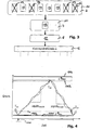
- Fig. 4 shows a representation of the real pressure curve 105 in the pressurized fluid system during a periodic time interval T switching .
- the length of the periodic time interval T switching This concerns just the length of a switching game.
- the controller determines an individual cut-off pressure 103 for the compressors 2 to be switched from load within the available pressure margin according to principles of energy optimization.
- the pressure margin is in this case the pressure range between a not to be exceeded adaptation pressure 103 and a not to be exceeded upper pressure limit 104.
- the energetically optimal switching cycle pressure difference and the energetically optimal cut-off pressure 103 is calculated mathematically-analytically for the compressors 2 to be switched from load as energetic optimum.
- the control method 41 regulates the cut-off pressure 103 of the compressors 2 to be switched in such a way that the total total power loss dependent on the switching cycle (total loss work per periodic time interval T switching ) becomes minimal.
- ⁇ W load is the loss work of the load-running compressors per cycle due to the pressure increase compared to the connection pressure, AW Leer, the idle loss work the switching compressors per cycle due to their idle powers and their lag time, ⁇ W switching the switching loss work per switching cycle of the switching compressors 2 due to the slow internal pressure compensation operation when switching to idle, possibly a motor revival and the internal pressure equalization when switching to load, T switching the switching cycle which extends over a periodic increase in pressure and the subsequent pressure drop over time.
- ⁇ W load 0.5 ⁇ r load ⁇ ⁇ p switching 2 ⁇ P last1 /
- r load is the relative increase in the load capacity of the load-traveling compressor 2 per pressure unit, ⁇ p switching the switching cycle pressure difference, P Last1 the load capacity of the compressors running during the pressure curve in the direction of cut-off 103, including the compressors 2 to be switched, at cut-in pressure 102,
- ffen1 the amount of the prospective average pressure rise during the real pressure curve in the direction of the cut-off pressure 103, calculated on the basis of an appropriate period, P Last2 the load power of the load during the pressure curve in the direction of Zuschaltbuch 102 running compressors 2, excluding the switching to compressors 2, at the Zuschalttik 102 ,
- P Leer is the idling power of the individual compressors to be switched and T Leer the follow-up time during idling of the individual compressors to be switched limited to a time between switching off and the connection.
- T switching ⁇ p switching ⁇ 1 /
- the calculation of the energy-optimal switching cycle pressure difference ⁇ p switching, opt can be with equation (1) by simply inserting the terms for the individual loss work ⁇ W load , ⁇ W empty , ⁇ W switching and the length of the periodic time interval (switching cycle) T switch in the formula according to Equation 1 for the dependent on the switching cycle power loss P v , by subsequent derivation after the switching cycle pressure difference ⁇ p switching and calculate corresponding zeroing of the derivative. Consequently, the energy-optimal switching cycle pressure difference ⁇ p switching, opt can be represented as a mathematically easy to handle expression according to equation (6): ⁇ P switching .
- the energetically optimal switch-off pressure results in pressure fluid applications as the sum of the adaptation pressure 101 and the calculated energetically optimal switching clearance pressure difference ⁇ p switching, opt .
- the energy-optimal cut-off pressure 103 results as the difference between the two aforementioned values, as understood by the person skilled in the art.
- the execution control method takes into account the delay times of the individual compressors 2 or combinations of compressors 2, which are determined from the times between switching on and off of a compressor 2 and the times of actual implementation of the state change. Accordingly, the switch-on times T are also to be compared with the switch-off times T ab compared to the minimum pressure values of the real pressure curve 105 or, compared to the maximum pressure values, offset in time.
- FIG. 4 a partially idealized switching game for illustrative purposes.
- An upper pressure limit 104 is determined by the system, for example by the compressive strength of the components.
- the lowest line in the diagram represents the adaptation pressure 101 which has already been discussed several times.
- the pressure profile moves between a (local) minimum value P min and a (local) maximum value P max .
- T AB namely Upon reaching the cut-off pressure 103 with increasing pressure curve measures for reducing the generation of compressed pressure fluid are made, which affect so that the pressure briefly above the cut-off pressure 103 to the (local) maximum value P max increases, but then the pressure increase in one Pressure drop reverses.
- measures are taken to increase the production of compressed pressure fluid, so that although the pressure drops even further to a (local) minimum value P min , then the pressure drop is reversed to a renewed pressure rise.
Landscapes
- Engineering & Computer Science (AREA)
- Mechanical Engineering (AREA)
- General Engineering & Computer Science (AREA)
- Physics & Mathematics (AREA)
- Fluid Mechanics (AREA)
- General Physics & Mathematics (AREA)
- Automation & Control Theory (AREA)
- Computer Hardware Design (AREA)
- Control Of Positive-Displacement Pumps (AREA)
Claims (15)
- Procédé de commande d'une installation de compresseurs (1) qui comprend une pluralité de compresseurs (2),
sachant qu'une surpression prédéterminée doit être maintenue par l'installation de compresseurs (1) dans un système de fluide sous pression malgré le soutirage éventuellement fluctuant de fluide sous pression à partir du système de fluide sous pression,
sachant que des décisions relatives à des opérations de commutation sont prises à intervalles de temps fixes ou variables pour adapter le système à des conditions actuelles, sachant que- à une étape de présélection (10), compte tenu des conditions actuelles, des alternatives de commutation (13) sont exclues de la pluralité d'alternatives de commutation (13) disponibles de manière combinatoire,- à une étape de sélection principale (11), des alternatives de commutation (13) restantes sont soupesées entre elles en se basant sur un ou plusieurs critères d'optimisation et l'alternative de commutation (13) optimale selon les critères spécifiés est sélectionnée et- à une étape de commande (12), l'alternative de commutation (13) sélectionnée est sortie pour mise en oeuvre dans l'installation de compresseurs (1). - Procédé selon la revendication 1, caractérisé en ce que la commande de l'installation (1) prend, en cas d'atteinte d'une pression d'enclenchement (102) éventuellement variable, des mesures pour augmenter la production de fluide sous pression comprimé et, en cas d'atteinte d'une pression de déclenchement (103) éventuellement variable, des mesures pour réduire la production de fluide sous pression comprimé.
- Procédé selon la revendication 1 ou 2,
sachant que des mesures sont prises par la commande de l'installation pour augmenter la production de fluide sous pression comprimé en cas d'atteinte d'une pression d'enclenchement (102) éventuellement variable et pour réduire la production de fluide sous pression comprimé en cas d'atteinte d'une pression de déclenchement (103), sachant que la pression de déclenchement (103) est variable et qu'elle est modifiable en fonction de la configuration actuelle de l'installation de compresseurs (1) et/ou compte tenu d'une opération de commutation définie. - Procédé selon la revendication 2 ou 3, caractérisé en ce que la pression de déclenchement (103) optimale est déterminée en minimisant par calcul le quotient résultant du travail de perte total dans un intervalle de temps périodique prédéfini relatif à une alternative de commutation (13) et de l'intervalle de temps lui-même, sachant que le travail de perte total comprend la somme du travail de perte de tous les compresseurs (2) fonctionnant en charge dans l'intervalle de temps, du travail de perte en marche à vide de tous les compresseurs (2) à enclencher dans l'intervalle de temps et du travail de perte de commutation de tous les compresseurs (2) à enclencher et à déclencher dans l'intervalle de temps.
- Procédé selon l'une des revendications 1 à 4, caractérisé en ce que des alternatives de commutation (13) pour réduire la production de fluide sous pression sont évaluées selon d'autres critères d'optimisation que des alternatives de commutation (13) pour augmenter la production de fluide sous pression.
- Procédé selon l'une des revendications 1 à 5, caractérisé en ce que le soupèsement et la sélection d'alternatives de commutation (13) pour réduire la production de fluide sous pression sont effectués selon des critères d'optimisation qui prennent en compte prioritairement ou exclusivement la dépense d'énergie totale respective des diverses alternatives de commutation (13) envisagées.
- Procédé selon la revendication 6, caractérisé en ce que, dans la prise en compte de la dépense d'énergie totale de diverses alternatives de commutation (13), sont au moins inclus :- les besoins en énergie des compresseurs fonctionnant en charge et/ou- les pertes en marche à vide des compresseurs à commuter en marche à vide ou à l'arrêt et/ou- les pertes en marche à vide des compresseurs qui se trouvent en marche à vide et/ou- l'énergie de perte de commutation des compresseurs à commuter par alternative de commutation (13).
- Procédé selon l'une des revendications 1 à 7, caractérisé en ce que l'évaluation et la sélection des alternatives de commutation (13) s'effectuent en temps réel.
- Procédé selon l'une des revendications 1 à 8, caractérisé en ce que la commande de l'installation (1) s'effectue compte tenu de grandeurs d'expérience issues d'opérations de commutation passées (commande adaptative).
- Procédé selon la revendication 9, caractérisé en ce que les grandeurs d'expérience comprennent :- un degré de besoins en énergie (besoins en énergie par quantité de fluide) de compresseurs (2) individuels ou de certaines combinaisons de compresseurs (2) et/ou- des temps de réaction d'enclenchement des compresseurs (2) et/ou- des comportements de consommation des consommateurs de fluide sous pression et/ou- une grandeur de l'accumulateur de pression et/ou- un degré de compensation de pression des compresseurs (2) ou de certaines combinaisons de compresseurs (2).
- Procédé selon l'une des revendications 1 à 8, caractérisé en ce que, lors de la détermination des alternatives de commutation (13), de préférence les compresseurs (2) ou combinaisons de compresseurs (2) qui présentent des valeurs favorables de grandeurs d'expérience pour le degré de besoins en énergie sont sélectionnés comme compresseurs (2) à commuter en charge.
- Procédé selon l'une des revendications 1 à 9, caractérisé en ce que, lors de la détermination des alternatives de commutation (13), de préférence les compresseurs (2) qui se trouvent en marche à vide et présentent encore un temps de marche à vide résiduel élevé, et/ou pour des compresseurs (2) à commuter en marche à vide ou à l'arrêt, de préférence les compresseurs (2) qui présentent un travail de marche à vide résiduel peu élevé, sont sélectionnés comme compresseurs (2) à commuter en charge.
- Procédé selon l'une des revendications 1 à 10, caractérisé en ce que la détermination d'alternatives de commutation (13) et/ou la détermination d'une pression de déclenchement (103) et/ou la détermination d'une pression d'enclenchement (102) s'effectuent dans l'hypothèse d'un soutirage constant de fluide sous pression.
- Procédé selon l'une des revendications 1 à 11, caractérisé en ce que, lors de la détermination de plusieurs alternatives de commutation (13) comme étant équivalents sur le plan énergétique, d'autres critères sont en outre pris en compte lors de la sélection, comme le nombre d'heures de fonctionnement d'un compresseur (2) envisagé.
- Dispositif de commande (4) pour une installation de compresseurs (1) qui comprend une pluralité de compresseurs (2),
sachant qu'une surpression prédéterminée doit être maintenue par l'installation de compresseurs (1) dans un système de fluide sous pression malgré le soutirage éventuellement fluctuant de fluide sous pression à partir du système de fluide sous pression,
sachant que des décisions relatives à des opérations de commutation sont prises à intervalles de temps fixes ou variables pour l'adaptation du système à des conditions actuelles, et caractérisé en ce que le dispositif de commande comprend- un dispositif d'exclusion (6) qui, compte tenu des conditions actuelles, exclut des alternatives de commutation (13) de la pluralité d'alternatives de commutation (13) disponibles de manière combinatoire,- un dispositif de sélection (7) qui soupèse entre elles les alternatives de commutation (13) restantes en se basant sur un ou plusieurs critères d'optimisation et sélectionne une alternative de commutation (13) optimale selon les critères spécifiés ainsi que- un dispositif de sortie (8) qui est configuré pour sortir l'alternative de commutation (13) sélectionnée pour mise en oeuvre dans l'installation de compresseurs.
Priority Applications (2)
| Application Number | Priority Date | Filing Date | Title |
|---|---|---|---|
| EP21201091.2A EP3961038A1 (fr) | 2008-12-23 | 2009-12-23 | Procédé de commande d'une installation de compresseurs |
| EP12198935.4A EP2573400B1 (fr) | 2008-12-23 | 2009-12-23 | Procédé de commande d'une installation de compresseurs |
Applications Claiming Priority (2)
| Application Number | Priority Date | Filing Date | Title |
|---|---|---|---|
| DE102008064490.0A DE102008064490B4 (de) | 2008-12-23 | 2008-12-23 | Verfahren zum Steuern einer Kompressoranlage mittels rechnerischer Minimierung des Abschaltdrucks sowie Steuerungseinrichtung und Datensatz |
| PCT/EP2009/067851 WO2010072808A2 (fr) | 2008-12-23 | 2009-12-23 | Procédé de commande d'une installation de compresseurs |
Related Child Applications (3)
| Application Number | Title | Priority Date | Filing Date |
|---|---|---|---|
| EP12198935.4A Division-Into EP2573400B1 (fr) | 2008-12-23 | 2009-12-23 | Procédé de commande d'une installation de compresseurs |
| EP12198935.4A Division EP2573400B1 (fr) | 2008-12-23 | 2009-12-23 | Procédé de commande d'une installation de compresseurs |
| EP21201091.2A Division EP3961038A1 (fr) | 2008-12-23 | 2009-12-23 | Procédé de commande d'une installation de compresseurs |
Publications (2)
| Publication Number | Publication Date |
|---|---|
| EP2376784A2 EP2376784A2 (fr) | 2011-10-19 |
| EP2376784B1 true EP2376784B1 (fr) | 2018-03-21 |
Family
ID=42194212
Family Applications (3)
| Application Number | Title | Priority Date | Filing Date |
|---|---|---|---|
| EP12198935.4A Active EP2573400B1 (fr) | 2008-12-23 | 2009-12-23 | Procédé de commande d'une installation de compresseurs |
| EP09799640.9A Revoked EP2376784B1 (fr) | 2008-12-23 | 2009-12-23 | Procédé de commande d'une installation de compresseurs |
| EP21201091.2A Pending EP3961038A1 (fr) | 2008-12-23 | 2009-12-23 | Procédé de commande d'une installation de compresseurs |
Family Applications Before (1)
| Application Number | Title | Priority Date | Filing Date |
|---|---|---|---|
| EP12198935.4A Active EP2573400B1 (fr) | 2008-12-23 | 2009-12-23 | Procédé de commande d'une installation de compresseurs |
Family Applications After (1)
| Application Number | Title | Priority Date | Filing Date |
|---|---|---|---|
| EP21201091.2A Pending EP3961038A1 (fr) | 2008-12-23 | 2009-12-23 | Procédé de commande d'une installation de compresseurs |
Country Status (12)
| Country | Link |
|---|---|
| US (3) | US20110286860A1 (fr) |
| EP (3) | EP2573400B1 (fr) |
| JP (1) | JP5702302B2 (fr) |
| CN (1) | CN102265035B (fr) |
| AU (1) | AU2009331503B2 (fr) |
| BR (1) | BRPI0918207B1 (fr) |
| CA (1) | CA2747066C (fr) |
| DE (1) | DE102008064490B4 (fr) |
| ES (1) | ES2902991T3 (fr) |
| MX (1) | MX2011006811A (fr) |
| RU (1) | RU2539232C2 (fr) |
| WO (1) | WO2010072808A2 (fr) |
Families Citing this family (19)
| Publication number | Priority date | Publication date | Assignee | Title |
|---|---|---|---|---|
| DE102008064491A1 (de) * | 2008-12-23 | 2010-06-24 | Kaeser Kompressoren Gmbh | Simulationsgestütztes Verfahren zur Steuerung bzw. Regelung von Druckluftstationen |
| DE102008064490B4 (de) | 2008-12-23 | 2026-04-23 | Kaeser Kompressoren Se | Verfahren zum Steuern einer Kompressoranlage mittels rechnerischer Minimierung des Abschaltdrucks sowie Steuerungseinrichtung und Datensatz |
| DE102011111188A1 (de) † | 2011-08-25 | 2013-02-28 | Khs Gmbh | Vakuumeinrichtung für Anlagen zur Behandlung von Behältern, Anlage zur Behandlung von Behältern sowie Verfahren zur Steuerung einer Vakuumeirichtung |
| BE1021301B1 (nl) | 2013-09-05 | 2015-10-26 | Atlas Copco Airpower, Naamloze Vennootschap | Compressorinrichting |
| DE102013111218A1 (de) * | 2013-10-10 | 2015-04-16 | Kaeser Kompressoren Se | Elektronische Steuerungseinrichtung für eine Komponente der Drucklufterzeugung, Druckluftaufbereitung, Druckluftspeicherung und/oder Druckluftverteilung |
| TWI513900B (zh) * | 2014-02-14 | 2015-12-21 | Nat Univ Tsing Hua | Control Method of Compressed Air Production in Air Compressor Station |
| BE1024411B1 (nl) | 2016-02-23 | 2018-02-12 | Atlas Copco Airpower Naamloze Vennootschap | Werkwijze voor het bedienen van een vacuümpompsysteem en vacuümpompsysteem dat een dergelijke werkwijze toepast. |
| WO2017143410A1 (fr) * | 2016-02-23 | 2017-08-31 | Atlas Copco Airpower, Naamloze Vennootschap | Procédé de fonctionnement d'un système de pompe à vide et système de pompe à vide appliquant un tel procédé |
| US12215691B2 (en) | 2016-02-23 | 2025-02-04 | Atlas Copco Airpower, Naamloze Vennootschap | Method for operating a vacuum pump system and vacuum pump system applying such method |
| CN110500295B (zh) * | 2019-08-15 | 2020-07-31 | 西安陕鼓动力股份有限公司 | 一种多机并联离心压缩机组的自动并机操作方法 |
| BE1028894B1 (nl) * | 2020-12-16 | 2022-07-19 | Atlas Copco Airpower Nv | Werkwijze voor het beoordelen van een toestand van een pneumatisch net |
| DE102021118771A1 (de) | 2021-07-20 | 2023-01-26 | Kaeser Kompressoren Se | Verfahren zur Bereitstellung mindestens einer Auslegungskonfiguration einer Druckluftanlage |
| BE1029908B1 (nl) * | 2021-11-08 | 2023-06-05 | Atlas Copco Airpower Nv | Methode en werkwijze voor het op afstand beheren van een persluchtdistributiesysteem |
| CN114893402A (zh) * | 2022-04-06 | 2022-08-12 | 合肥工业大学 | 基于人工智能的并联空压机能耗调控方法及系统 |
| DE102022132003A1 (de) * | 2022-12-02 | 2024-06-13 | Kaeser Kompressoren Se | Verfahren zur steuerung einer kompressoranlage mit mehreren kompressoren |
| BE1031134B1 (nl) * | 2022-12-29 | 2025-01-07 | Atlas Copco Airpower Nv | Werkwijze, systeem en inrichting voor het besturen van een compressorsysteem |
| CN116658406B (zh) * | 2023-06-16 | 2025-09-23 | 三峡金沙江云川水电开发有限公司 | 一种低压用气系统在多种工况下控制方法及系统 |
| US12338810B1 (en) * | 2024-02-05 | 2025-06-24 | Dongguan Hesheng Machinery & Electric Co., Ltd. | Inflation control system having multiple air compressors |
| CN121738931B (zh) * | 2026-02-26 | 2026-04-28 | 沈阳鼓风机集团齿轮压缩机有限公司 | 串联多轴离心压缩机组的控制方法、装置和存储介质 |
Citations (4)
| Publication number | Priority date | Publication date | Assignee | Title |
|---|---|---|---|---|
| US4502842A (en) | 1983-02-02 | 1985-03-05 | Colt Industries Operating Corp. | Multiple compressor controller and method |
| US6419454B1 (en) | 2000-06-14 | 2002-07-16 | Leo P. Christiansen | Air compressor control sequencer |
| US20070077151A1 (en) | 2005-09-30 | 2007-04-05 | Takahisa Hirasawa | Control system for air-compressing apparatus |
| US20080131258A1 (en) | 2005-02-11 | 2008-06-05 | Helmut Liepold | Method for Optimizing the Functioning of a Plurality of Compressor Units and Corresponding Device |
Family Cites Families (25)
| Publication number | Priority date | Publication date | Assignee | Title |
|---|---|---|---|---|
| DE3332619A1 (de) | 1983-09-09 | 1985-03-28 | Knorr-Bremse GmbH, 8000 München | Einrichtung zur energieeinsparung bei kompressoren, insbesondere fuer kraftfahrzeuge |
| JPS60147585A (ja) * | 1984-01-11 | 1985-08-03 | Hitachi Ltd | 圧縮機の制御方法 |
| DE3937152A1 (de) | 1989-11-08 | 1991-05-16 | Gutehoffnungshuette Man | Verfahren zum optimierten betreiben zweier oder mehrerer kompressoren im parallel- oder reihenbetrieb |
| US5343384A (en) * | 1992-10-13 | 1994-08-30 | Ingersoll-Rand Company | Method and apparatus for controlling a system of compressors to achieve load sharing |
| US5713724A (en) * | 1994-11-23 | 1998-02-03 | Coltec Industries Inc. | System and methods for controlling rotary screw compressors |
| US5967761A (en) * | 1997-07-15 | 1999-10-19 | Ingersoll-Rand Company | Method for modulation lag compressor in multiple compressor system |
| DE19826169A1 (de) | 1998-06-13 | 1999-12-16 | Kaeser Kompressoren Gmbh | Elektronische Steuerung für Anlagen der Druckluft- und Vakuumerzeugung |
| JP4248077B2 (ja) * | 1999-04-14 | 2009-04-02 | 株式会社日立産機システム | 圧縮機装置 |
| US6233954B1 (en) * | 1999-04-28 | 2001-05-22 | Ingersoll-Rand Company | Method for controlling the operation of a compression system having a plurality of compressors |
| GB9912681D0 (en) * | 1999-06-02 | 1999-07-28 | Wabco Automotive Uk | Vehicle air braking systems |
| CN1291684A (zh) * | 1999-10-12 | 2001-04-18 | 兴立翔机电有限公司 | 空压机的变频恒压系统 |
| JP4520608B2 (ja) * | 2000-09-20 | 2010-08-11 | 株式会社日立プラントテクノロジー | スクリュー圧縮装置 |
| US6394120B1 (en) * | 2000-10-06 | 2002-05-28 | Scales Air Compressor | Method and control system for controlling multiple compressors |
| RU2181854C1 (ru) * | 2001-06-18 | 2002-04-27 | Закрытое акционерное общество "Научно-производственная фирма "Система-Сервис" | Способ управления работой комплекса агрегатов компрессорного цеха |
| US6816795B2 (en) * | 2001-09-14 | 2004-11-09 | David Vanderbeek | Compressed gas system |
| DE10208676A1 (de) | 2002-02-28 | 2003-09-04 | Man Turbomasch Ag Ghh Borsig | Verfahren zum Regeln von mehreren Strömungsmaschinen im Parallel- oder Reihenbetrieb |
| SE521518C2 (sv) | 2002-03-14 | 2003-11-11 | Intelligent Energy Networks Ab | Förfarande och system för att styra ett antal kompressorer |
| FR2839755B1 (fr) * | 2002-05-14 | 2006-02-03 | Air Liquide | Installation de production d'un gaz comprime, et procede d'exploitation de cette installation |
| BE1015460A3 (nl) * | 2003-04-04 | 2005-04-05 | Atlas Copco Airpower Nv | Werkwijze voor het sturen van een persluchtinstallatie met meerdere compressoren, stuurdoos daarbij toegepast, en persluchtinstallatie die deze werkwijze toepast. |
| JP2005290989A (ja) * | 2004-03-31 | 2005-10-20 | Yamatake Corp | 圧縮機設備の統合制御盤 |
| EP1811248A1 (fr) * | 2004-11-10 | 2007-07-25 | Daikin Industries, Ltd. | Appareil de congelation |
| FR2879770B1 (fr) | 2004-12-17 | 2007-03-30 | Air Liquide | Procede de controle des performances energetiques d'une unite industrielle |
| JP4737770B2 (ja) | 2006-09-12 | 2011-08-03 | アネスト岩田株式会社 | 真空ポンプの運転制御装置および方法 |
| DE102008064490B4 (de) | 2008-12-23 | 2026-04-23 | Kaeser Kompressoren Se | Verfahren zum Steuern einer Kompressoranlage mittels rechnerischer Minimierung des Abschaltdrucks sowie Steuerungseinrichtung und Datensatz |
| DE102008064491A1 (de) | 2008-12-23 | 2010-06-24 | Kaeser Kompressoren Gmbh | Simulationsgestütztes Verfahren zur Steuerung bzw. Regelung von Druckluftstationen |
-
2008
- 2008-12-23 DE DE102008064490.0A patent/DE102008064490B4/de active Active
-
2009
- 2009-12-23 EP EP12198935.4A patent/EP2573400B1/fr active Active
- 2009-12-23 BR BRPI0918207-1A patent/BRPI0918207B1/pt active IP Right Grant
- 2009-12-23 US US13/141,244 patent/US20110286860A1/en not_active Abandoned
- 2009-12-23 JP JP2011542827A patent/JP5702302B2/ja active Active
- 2009-12-23 AU AU2009331503A patent/AU2009331503B2/en active Active
- 2009-12-23 CA CA2747066A patent/CA2747066C/fr active Active
- 2009-12-23 MX MX2011006811A patent/MX2011006811A/es not_active Application Discontinuation
- 2009-12-23 RU RU2011130186/06A patent/RU2539232C2/ru active
- 2009-12-23 EP EP09799640.9A patent/EP2376784B1/fr not_active Revoked
- 2009-12-23 EP EP21201091.2A patent/EP3961038A1/fr active Pending
- 2009-12-23 WO PCT/EP2009/067851 patent/WO2010072808A2/fr not_active Ceased
- 2009-12-23 ES ES12198935T patent/ES2902991T3/es active Active
- 2009-12-23 CN CN200980152463.7A patent/CN102265035B/zh active Active
-
2017
- 2017-02-17 US US15/435,530 patent/US11162492B2/en active Active
-
2021
- 2021-11-01 US US17/516,114 patent/US20220049693A1/en active Pending
Patent Citations (4)
| Publication number | Priority date | Publication date | Assignee | Title |
|---|---|---|---|---|
| US4502842A (en) | 1983-02-02 | 1985-03-05 | Colt Industries Operating Corp. | Multiple compressor controller and method |
| US6419454B1 (en) | 2000-06-14 | 2002-07-16 | Leo P. Christiansen | Air compressor control sequencer |
| US20080131258A1 (en) | 2005-02-11 | 2008-06-05 | Helmut Liepold | Method for Optimizing the Functioning of a Plurality of Compressor Units and Corresponding Device |
| US20070077151A1 (en) | 2005-09-30 | 2007-04-05 | Takahisa Hirasawa | Control system for air-compressing apparatus |
Also Published As
| Publication number | Publication date |
|---|---|
| WO2010072808A3 (fr) | 2011-07-07 |
| US20220049693A1 (en) | 2022-02-17 |
| EP2376784A2 (fr) | 2011-10-19 |
| BRPI0918207B1 (pt) | 2022-03-03 |
| WO2010072808A2 (fr) | 2010-07-01 |
| US11162492B2 (en) | 2021-11-02 |
| DE102008064490B4 (de) | 2026-04-23 |
| EP2573400B1 (fr) | 2021-10-13 |
| CN102265035B (zh) | 2015-05-06 |
| DE102008064490A1 (de) | 2010-06-24 |
| BRPI0918207A2 (pt) | 2015-12-08 |
| US20110286860A1 (en) | 2011-11-24 |
| AU2009331503A2 (en) | 2012-02-09 |
| AU2009331503B2 (en) | 2015-05-28 |
| CA2747066A1 (fr) | 2010-07-01 |
| US20170159652A1 (en) | 2017-06-08 |
| RU2539232C2 (ru) | 2015-01-20 |
| AU2009331503A1 (en) | 2011-07-07 |
| EP2573400A2 (fr) | 2013-03-27 |
| CN102265035A (zh) | 2011-11-30 |
| ES2902991T3 (es) | 2022-03-30 |
| CA2747066C (fr) | 2017-03-21 |
| EP3961038A1 (fr) | 2022-03-02 |
| EP2573400A3 (fr) | 2017-11-22 |
| JP2012513564A (ja) | 2012-06-14 |
| MX2011006811A (es) | 2011-07-20 |
| RU2011130186A (ru) | 2013-01-27 |
| JP5702302B2 (ja) | 2015-04-15 |
Similar Documents
| Publication | Publication Date | Title |
|---|---|---|
| EP2376784B1 (fr) | Procédé de commande d'une installation de compresseurs | |
| EP1846660B1 (fr) | Procede d'optimisation du fonctionnement de plusieurs groupes de compresseurs et dispositif correspondant | |
| EP2469094B1 (fr) | Procédé de fonctionnement d'un agrégat de pompes doubles ou multipompes | |
| DE10013098C2 (de) | Anlage zur Erzeugung von Druckluft | |
| EP2678563B1 (fr) | Opération à performance améliorée d'une pompe entrainée par un moteur électrique par rétroaction positive | |
| EP3655663B1 (fr) | Procédé de réglage d'au moins deux ventilateurs | |
| EP2579112A1 (fr) | Dispositif de régulation | |
| EP1752852B1 (fr) | Procédé destiné au réglage de la température du caloporteur d'un système de chauffage et/ou de refroidissement | |
| EP3924670A1 (fr) | Procédé pour réguler une pompe de circulation | |
| DE102006013098C5 (de) | Verfahren und Vorrichtung zur bedarfsgeführten Wärmebereitstellung in einer Heizungsanlage | |
| WO2012167959A1 (fr) | Dispositif à fluide | |
| EP4189295B1 (fr) | Procédé de contrôle d'une pompe de circulation, en particulier d'une pompe de chauffage | |
| EP3895819B1 (fr) | Fonctionnement d'un dispositif de refrodissement avec une pression de fonctionnement minimale | |
| EP3267039A1 (fr) | Procédé et système de réglage d'une installation de pompage | |
| DE102010017208B4 (de) | Kühlmittelsystem für Werkzeugmaschinen | |
| EP3354372B1 (fr) | Système de refroidissement, installation métallurgique et procédé de fonctionnement d'un système de refroidissement | |
| EP4107594A1 (fr) | Procédé d'automatisation d'une installation métallurgique, en particulier une installation de laminage de bandes métalliques | |
| AT528411B1 (de) | Akkusystem für Stopfaggregat | |
| AT527755B1 (de) | Temperiersystem zum Temperieren von Komponenten von Produktionszellen | |
| EP1096635A2 (fr) | Procédé de régulation et régulateur pour actionneurs à commande électrique | |
| EP1764562A1 (fr) | Procédé d'exploitation d'une cellule de combustion dans un système de chauffage | |
| EP4446660A1 (fr) | Régulation de température de départ optimisée par cop pour une pompe à chaleur | |
| EP4720520A1 (fr) | Procédé d'actionnement d'un système à pompes multiples comprenant au moins deux pompes qui peuvent être actionnées hydrauliquement en parallèle, et système à pompes multiples | |
| WO2013171041A1 (fr) | Système de réglage d'un ensemble vérin hydraulique commandé par une seule vanne | |
| DE102012209683A1 (de) | Walze |
Legal Events
| Date | Code | Title | Description |
|---|---|---|---|
| PUAI | Public reference made under article 153(3) epc to a published international application that has entered the european phase |
Free format text: ORIGINAL CODE: 0009012 |
|
| 17P | Request for examination filed |
Effective date: 20110711 |
|
| AK | Designated contracting states |
Kind code of ref document: A2 Designated state(s): AT BE BG CH CY CZ DE DK EE ES FI FR GB GR HR HU IE IS IT LI LT LU LV MC MK MT NL NO PL PT RO SE SI SK SM TR |
|
| DAX | Request for extension of the european patent (deleted) | ||
| RAP1 | Party data changed (applicant data changed or rights of an application transferred) |
Owner name: KAESER KOMPRESSOREN AG |
|
| RAP1 | Party data changed (applicant data changed or rights of an application transferred) |
Owner name: KAESER KOMPRESSOREN SE |
|
| RAP1 | Party data changed (applicant data changed or rights of an application transferred) |
Owner name: KAESER KOMPRESSOREN SE |
|
| 17Q | First examination report despatched |
Effective date: 20160708 |
|
| STAA | Information on the status of an ep patent application or granted ep patent |
Free format text: STATUS: EXAMINATION IS IN PROGRESS |
|
| GRAP | Despatch of communication of intention to grant a patent |
Free format text: ORIGINAL CODE: EPIDOSNIGR1 |
|
| STAA | Information on the status of an ep patent application or granted ep patent |
Free format text: STATUS: GRANT OF PATENT IS INTENDED |
|
| INTG | Intention to grant announced |
Effective date: 20170405 |
|
| GRAS | Grant fee paid |
Free format text: ORIGINAL CODE: EPIDOSNIGR3 |
|
| GRAJ | Information related to disapproval of communication of intention to grant by the applicant or resumption of examination proceedings by the epo deleted |
Free format text: ORIGINAL CODE: EPIDOSDIGR1 |
|
| GRAL | Information related to payment of fee for publishing/printing deleted |
Free format text: ORIGINAL CODE: EPIDOSDIGR3 |
|
| STAA | Information on the status of an ep patent application or granted ep patent |
Free format text: STATUS: EXAMINATION IS IN PROGRESS |
|
| INTC | Intention to grant announced (deleted) | ||
| GRAP | Despatch of communication of intention to grant a patent |
Free format text: ORIGINAL CODE: EPIDOSNIGR1 |
|
| STAA | Information on the status of an ep patent application or granted ep patent |
Free format text: STATUS: GRANT OF PATENT IS INTENDED |
|
| INTG | Intention to grant announced |
Effective date: 20171009 |
|
| GRAA | (expected) grant |
Free format text: ORIGINAL CODE: 0009210 |
|
| STAA | Information on the status of an ep patent application or granted ep patent |
Free format text: STATUS: THE PATENT HAS BEEN GRANTED |
|
| AK | Designated contracting states |
Kind code of ref document: B1 Designated state(s): AT BE BG CH CY CZ DE DK EE ES FI FR GB GR HR HU IE IS IT LI LT LU LV MC MK MT NL NO PL PT RO SE SI SK SM TR |
|
| REG | Reference to a national code |
Ref country code: GB Ref legal event code: FG4D Free format text: NOT ENGLISH |
|
| REG | Reference to a national code |
Ref country code: CH Ref legal event code: EP |
|
| REG | Reference to a national code |
Ref country code: AT Ref legal event code: REF Ref document number: 981423 Country of ref document: AT Kind code of ref document: T Effective date: 20180415 |
|
| REG | Reference to a national code |
Ref country code: IE Ref legal event code: FG4D Free format text: LANGUAGE OF EP DOCUMENT: GERMAN |
|
| REG | Reference to a national code |
Ref country code: DE Ref legal event code: R096 Ref document number: 502009014843 Country of ref document: DE |
|
| REG | Reference to a national code |
Ref country code: NL Ref legal event code: MP Effective date: 20180321 |
|
| PG25 | Lapsed in a contracting state [announced via postgrant information from national office to epo] |
Ref country code: CY Free format text: LAPSE BECAUSE OF FAILURE TO SUBMIT A TRANSLATION OF THE DESCRIPTION OR TO PAY THE FEE WITHIN THE PRESCRIBED TIME-LIMIT Effective date: 20180321 Ref country code: LT Free format text: LAPSE BECAUSE OF FAILURE TO SUBMIT A TRANSLATION OF THE DESCRIPTION OR TO PAY THE FEE WITHIN THE PRESCRIBED TIME-LIMIT Effective date: 20180321 Ref country code: FI Free format text: LAPSE BECAUSE OF FAILURE TO SUBMIT A TRANSLATION OF THE DESCRIPTION OR TO PAY THE FEE WITHIN THE PRESCRIBED TIME-LIMIT Effective date: 20180321 Ref country code: NO Free format text: LAPSE BECAUSE OF FAILURE TO SUBMIT A TRANSLATION OF THE DESCRIPTION OR TO PAY THE FEE WITHIN THE PRESCRIBED TIME-LIMIT Effective date: 20180621 Ref country code: HR Free format text: LAPSE BECAUSE OF FAILURE TO SUBMIT A TRANSLATION OF THE DESCRIPTION OR TO PAY THE FEE WITHIN THE PRESCRIBED TIME-LIMIT Effective date: 20180321 |
|
| REG | Reference to a national code |
Ref country code: LT Ref legal event code: MG4D |
|
| PG25 | Lapsed in a contracting state [announced via postgrant information from national office to epo] |
Ref country code: LV Free format text: LAPSE BECAUSE OF FAILURE TO SUBMIT A TRANSLATION OF THE DESCRIPTION OR TO PAY THE FEE WITHIN THE PRESCRIBED TIME-LIMIT Effective date: 20180321 Ref country code: SE Free format text: LAPSE BECAUSE OF FAILURE TO SUBMIT A TRANSLATION OF THE DESCRIPTION OR TO PAY THE FEE WITHIN THE PRESCRIBED TIME-LIMIT Effective date: 20180321 Ref country code: BG Free format text: LAPSE BECAUSE OF FAILURE TO SUBMIT A TRANSLATION OF THE DESCRIPTION OR TO PAY THE FEE WITHIN THE PRESCRIBED TIME-LIMIT Effective date: 20180621 Ref country code: GR Free format text: LAPSE BECAUSE OF FAILURE TO SUBMIT A TRANSLATION OF THE DESCRIPTION OR TO PAY THE FEE WITHIN THE PRESCRIBED TIME-LIMIT Effective date: 20180622 |
|
| PG25 | Lapsed in a contracting state [announced via postgrant information from national office to epo] |
Ref country code: MT Free format text: LAPSE BECAUSE OF FAILURE TO SUBMIT A TRANSLATION OF THE DESCRIPTION OR TO PAY THE FEE WITHIN THE PRESCRIBED TIME-LIMIT Effective date: 20180321 |
|
| PG25 | Lapsed in a contracting state [announced via postgrant information from national office to epo] |
Ref country code: RO Free format text: LAPSE BECAUSE OF FAILURE TO SUBMIT A TRANSLATION OF THE DESCRIPTION OR TO PAY THE FEE WITHIN THE PRESCRIBED TIME-LIMIT Effective date: 20180321 Ref country code: ES Free format text: LAPSE BECAUSE OF FAILURE TO SUBMIT A TRANSLATION OF THE DESCRIPTION OR TO PAY THE FEE WITHIN THE PRESCRIBED TIME-LIMIT Effective date: 20180321 Ref country code: NL Free format text: LAPSE BECAUSE OF FAILURE TO SUBMIT A TRANSLATION OF THE DESCRIPTION OR TO PAY THE FEE WITHIN THE PRESCRIBED TIME-LIMIT Effective date: 20180321 Ref country code: EE Free format text: LAPSE BECAUSE OF FAILURE TO SUBMIT A TRANSLATION OF THE DESCRIPTION OR TO PAY THE FEE WITHIN THE PRESCRIBED TIME-LIMIT Effective date: 20180321 Ref country code: PL Free format text: LAPSE BECAUSE OF FAILURE TO SUBMIT A TRANSLATION OF THE DESCRIPTION OR TO PAY THE FEE WITHIN THE PRESCRIBED TIME-LIMIT Effective date: 20180321 |
|
| PG25 | Lapsed in a contracting state [announced via postgrant information from national office to epo] |
Ref country code: SK Free format text: LAPSE BECAUSE OF FAILURE TO SUBMIT A TRANSLATION OF THE DESCRIPTION OR TO PAY THE FEE WITHIN THE PRESCRIBED TIME-LIMIT Effective date: 20180321 Ref country code: SM Free format text: LAPSE BECAUSE OF FAILURE TO SUBMIT A TRANSLATION OF THE DESCRIPTION OR TO PAY THE FEE WITHIN THE PRESCRIBED TIME-LIMIT Effective date: 20180321 Ref country code: CZ Free format text: LAPSE BECAUSE OF FAILURE TO SUBMIT A TRANSLATION OF THE DESCRIPTION OR TO PAY THE FEE WITHIN THE PRESCRIBED TIME-LIMIT Effective date: 20180321 |
|
| REG | Reference to a national code |
Ref country code: DE Ref legal event code: R026 Ref document number: 502009014843 Country of ref document: DE |
|
| PLBI | Opposition filed |
Free format text: ORIGINAL CODE: 0009260 |
|
| PG25 | Lapsed in a contracting state [announced via postgrant information from national office to epo] |
Ref country code: PT Free format text: LAPSE BECAUSE OF FAILURE TO SUBMIT A TRANSLATION OF THE DESCRIPTION OR TO PAY THE FEE WITHIN THE PRESCRIBED TIME-LIMIT Effective date: 20180723 |
|
| PLAX | Notice of opposition and request to file observation + time limit sent |
Free format text: ORIGINAL CODE: EPIDOSNOBS2 |
|
| 26 | Opposition filed |
Opponent name: WF STEUERUNGSTECHNIK GMBH Effective date: 20181218 |
|
| PG25 | Lapsed in a contracting state [announced via postgrant information from national office to epo] |
Ref country code: DK Free format text: LAPSE BECAUSE OF FAILURE TO SUBMIT A TRANSLATION OF THE DESCRIPTION OR TO PAY THE FEE WITHIN THE PRESCRIBED TIME-LIMIT Effective date: 20180321 |
|
| PLBB | Reply of patent proprietor to notice(s) of opposition received |
Free format text: ORIGINAL CODE: EPIDOSNOBS3 |
|
| PG25 | Lapsed in a contracting state [announced via postgrant information from national office to epo] |
Ref country code: SI Free format text: LAPSE BECAUSE OF FAILURE TO SUBMIT A TRANSLATION OF THE DESCRIPTION OR TO PAY THE FEE WITHIN THE PRESCRIBED TIME-LIMIT Effective date: 20180321 |
|
| PLAY | Examination report in opposition despatched + time limit |
Free format text: ORIGINAL CODE: EPIDOSNORE2 |
|
| REG | Reference to a national code |
Ref country code: CH Ref legal event code: PL |
|
| PLBC | Reply to examination report in opposition received |
Free format text: ORIGINAL CODE: EPIDOSNORE3 |
|
| PG25 | Lapsed in a contracting state [announced via postgrant information from national office to epo] |
Ref country code: LU Free format text: LAPSE BECAUSE OF NON-PAYMENT OF DUE FEES Effective date: 20181223 Ref country code: MC Free format text: LAPSE BECAUSE OF FAILURE TO SUBMIT A TRANSLATION OF THE DESCRIPTION OR TO PAY THE FEE WITHIN THE PRESCRIBED TIME-LIMIT Effective date: 20180321 |
|
| REG | Reference to a national code |
Ref country code: IE Ref legal event code: MM4A |
|
| PG25 | Lapsed in a contracting state [announced via postgrant information from national office to epo] |
Ref country code: IE Free format text: LAPSE BECAUSE OF NON-PAYMENT OF DUE FEES Effective date: 20181223 |
|
| PG25 | Lapsed in a contracting state [announced via postgrant information from national office to epo] |
Ref country code: CH Free format text: LAPSE BECAUSE OF NON-PAYMENT OF DUE FEES Effective date: 20181231 Ref country code: LI Free format text: LAPSE BECAUSE OF NON-PAYMENT OF DUE FEES Effective date: 20181231 |
|
| REG | Reference to a national code |
Ref country code: AT Ref legal event code: MM01 Ref document number: 981423 Country of ref document: AT Kind code of ref document: T Effective date: 20181223 |
|
| PG25 | Lapsed in a contracting state [announced via postgrant information from national office to epo] |
Ref country code: TR Free format text: LAPSE BECAUSE OF FAILURE TO SUBMIT A TRANSLATION OF THE DESCRIPTION OR TO PAY THE FEE WITHIN THE PRESCRIBED TIME-LIMIT Effective date: 20180321 |
|
| PG25 | Lapsed in a contracting state [announced via postgrant information from national office to epo] |
Ref country code: AT Free format text: LAPSE BECAUSE OF NON-PAYMENT OF DUE FEES Effective date: 20181223 |
|
| PG25 | Lapsed in a contracting state [announced via postgrant information from national office to epo] |
Ref country code: MK Free format text: LAPSE BECAUSE OF NON-PAYMENT OF DUE FEES Effective date: 20180321 Ref country code: HU Free format text: LAPSE BECAUSE OF FAILURE TO SUBMIT A TRANSLATION OF THE DESCRIPTION OR TO PAY THE FEE WITHIN THE PRESCRIBED TIME-LIMIT; INVALID AB INITIO Effective date: 20091223 |
|
| PG25 | Lapsed in a contracting state [announced via postgrant information from national office to epo] |
Ref country code: IS Free format text: LAPSE BECAUSE OF FAILURE TO SUBMIT A TRANSLATION OF THE DESCRIPTION OR TO PAY THE FEE WITHIN THE PRESCRIBED TIME-LIMIT Effective date: 20180721 |
|
| PLCK | Communication despatched that opposition was rejected |
Free format text: ORIGINAL CODE: EPIDOSNREJ1 |
|
| APBM | Appeal reference recorded |
Free format text: ORIGINAL CODE: EPIDOSNREFNO |
|
| APBP | Date of receipt of notice of appeal recorded |
Free format text: ORIGINAL CODE: EPIDOSNNOA2O |
|
| APAH | Appeal reference modified |
Free format text: ORIGINAL CODE: EPIDOSCREFNO |
|
| APBQ | Date of receipt of statement of grounds of appeal recorded |
Free format text: ORIGINAL CODE: EPIDOSNNOA3O |
|
| PGFP | Annual fee paid to national office [announced via postgrant information from national office to epo] |
Ref country code: GB Payment date: 20221220 Year of fee payment: 14 Ref country code: FR Payment date: 20221222 Year of fee payment: 14 |
|
| REG | Reference to a national code |
Ref country code: DE Ref legal event code: R103 Ref document number: 502009014843 Country of ref document: DE Ref country code: DE Ref legal event code: R064 Ref document number: 502009014843 Country of ref document: DE |
|
| APBU | Appeal procedure closed |
Free format text: ORIGINAL CODE: EPIDOSNNOA9O |
|
| PGFP | Annual fee paid to national office [announced via postgrant information from national office to epo] |
Ref country code: BE Payment date: 20221226 Year of fee payment: 14 |
|
| RDAF | Communication despatched that patent is revoked |
Free format text: ORIGINAL CODE: EPIDOSNREV1 |
|
| STAA | Information on the status of an ep patent application or granted ep patent |
Free format text: STATUS: PATENT REVOKED |
|
| RDAG | Patent revoked |
Free format text: ORIGINAL CODE: 0009271 |
|
| REG | Reference to a national code |
Ref country code: CH Ref legal event code: PL |
|
| 27W | Patent revoked |
Effective date: 20230210 |
|
| GBPR | Gb: patent revoked under art. 102 of the ep convention designating the uk as contracting state |
Effective date: 20230210 |
|
| PGFP | Annual fee paid to national office [announced via postgrant information from national office to epo] |
Ref country code: IT Payment date: 20221222 Year of fee payment: 14 Ref country code: DE Payment date: 20221230 Year of fee payment: 14 |
|
| POAG | Date of filing of petition for review recorded |
Free format text: ORIGINAL CODE: EPIDOSNPRV3 |
|
| POAH | Number of petition for review recorded |
Free format text: ORIGINAL CODE: EPIDOSNPRV1 |
|
| POAI | Petitioner in petition for review recorded |
Free format text: ORIGINAL CODE: EPIDOSNPRV2 |
|
| REG | Reference to a national code |
Ref country code: AT Ref legal event code: MA03 Ref document number: 981423 Country of ref document: AT Kind code of ref document: T Effective date: 20230210 |
|
| P01 | Opt-out of the competence of the unified patent court (upc) registered |
Effective date: 20230531 |
|
| POAD | Information related to date of filing of petition for review deleted |
Free format text: ORIGINAL CODE: EPIDOSDPRV3 |
|
| POAK | Decision taken: petition for review obviously unsubstantiated |
Free format text: ORIGINAL CODE: 0009255 |
|
| PRVN | Petition for review not allowed |
Free format text: PETITION FOR REVIEW OBVIOUSLY UNSUBSTANTIATED Effective date: 20250528 |