EP3655663B1 - Procédé de réglage d'au moins deux ventilateurs - Google Patents
Procédé de réglage d'au moins deux ventilateurs Download PDFInfo
- Publication number
- EP3655663B1 EP3655663B1 EP18740797.8A EP18740797A EP3655663B1 EP 3655663 B1 EP3655663 B1 EP 3655663B1 EP 18740797 A EP18740797 A EP 18740797A EP 3655663 B1 EP3655663 B1 EP 3655663B1
- Authority
- EP
- European Patent Office
- Prior art keywords
- fans
- fan
- volume flow
- optimized
- setpoint
- Prior art date
- Legal status (The legal status is an assumption and is not a legal conclusion. Google has not performed a legal analysis and makes no representation as to the accuracy of the status listed.)
- Active
Links
Images

Classifications
-
- F—MECHANICAL ENGINEERING; LIGHTING; HEATING; WEAPONS; BLASTING
- F04—POSITIVE - DISPLACEMENT MACHINES FOR LIQUIDS; PUMPS FOR LIQUIDS OR ELASTIC FLUIDS
- F04D—NON-POSITIVE-DISPLACEMENT PUMPS
- F04D25/00—Pumping installations or systems
- F04D25/16—Combinations of two or more pumps ; Producing two or more separate gas flows
- F04D25/166—Combinations of two or more pumps ; Producing two or more separate gas flows using fans
-
- F—MECHANICAL ENGINEERING; LIGHTING; HEATING; WEAPONS; BLASTING
- F04—POSITIVE - DISPLACEMENT MACHINES FOR LIQUIDS; PUMPS FOR LIQUIDS OR ELASTIC FLUIDS
- F04D—NON-POSITIVE-DISPLACEMENT PUMPS
- F04D27/00—Control, e.g. regulation, of pumps, pumping installations or pumping systems specially adapted for elastic fluids
- F04D27/004—Control, e.g. regulation, of pumps, pumping installations or pumping systems specially adapted for elastic fluids by varying driving speed
-
- F—MECHANICAL ENGINEERING; LIGHTING; HEATING; WEAPONS; BLASTING
- F04—POSITIVE - DISPLACEMENT MACHINES FOR LIQUIDS; PUMPS FOR LIQUIDS OR ELASTIC FLUIDS
- F04D—NON-POSITIVE-DISPLACEMENT PUMPS
- F04D25/00—Pumping installations or systems
- F04D25/02—Units comprising pumps and their driving means
- F04D25/08—Units comprising pumps and their driving means the working fluid being air, e.g. for ventilation
-
- F—MECHANICAL ENGINEERING; LIGHTING; HEATING; WEAPONS; BLASTING
- F24—HEATING; RANGES; VENTILATING
- F24F—AIR-CONDITIONING; AIR-HUMIDIFICATION; VENTILATION; USE OF AIR CURRENTS FOR SCREENING
- F24F11/00—Control or safety arrangements
- F24F11/0001—Control or safety arrangements for ventilation
-
- F—MECHANICAL ENGINEERING; LIGHTING; HEATING; WEAPONS; BLASTING
- F24—HEATING; RANGES; VENTILATING
- F24F—AIR-CONDITIONING; AIR-HUMIDIFICATION; VENTILATION; USE OF AIR CURRENTS FOR SCREENING
- F24F11/00—Control or safety arrangements
- F24F11/30—Control or safety arrangements for purposes related to the operation of the system, e.g. for safety or monitoring
- F24F11/46—Improving electric energy efficiency or saving
-
- F—MECHANICAL ENGINEERING; LIGHTING; HEATING; WEAPONS; BLASTING
- F24—HEATING; RANGES; VENTILATING
- F24F—AIR-CONDITIONING; AIR-HUMIDIFICATION; VENTILATION; USE OF AIR CURRENTS FOR SCREENING
- F24F11/00—Control or safety arrangements
- F24F11/70—Control systems characterised by their outputs; Constructional details thereof
- F24F11/72—Control systems characterised by their outputs; Constructional details thereof for controlling the supply of treated air, e.g. its pressure
- F24F11/74—Control systems characterised by their outputs; Constructional details thereof for controlling the supply of treated air, e.g. its pressure for controlling air flow rate or air velocity
-
- Y—GENERAL TAGGING OF NEW TECHNOLOGICAL DEVELOPMENTS; GENERAL TAGGING OF CROSS-SECTIONAL TECHNOLOGIES SPANNING OVER SEVERAL SECTIONS OF THE IPC; TECHNICAL SUBJECTS COVERED BY FORMER USPC CROSS-REFERENCE ART COLLECTIONS [XRACs] AND DIGESTS
- Y02—TECHNOLOGIES OR APPLICATIONS FOR MITIGATION OR ADAPTATION AGAINST CLIMATE CHANGE
- Y02B—CLIMATE CHANGE MITIGATION TECHNOLOGIES RELATED TO BUILDINGS, e.g. HOUSING, HOUSE APPLIANCES OR RELATED END-USER APPLICATIONS
- Y02B30/00—Energy efficient heating, ventilation or air conditioning [HVAC]
- Y02B30/70—Efficient control or regulation technologies, e.g. for control of refrigerant flow, motor or heating
Definitions
- the invention relates to a control method for the energy-optimized or efficiency-optimized operation of at least two or a plurality of fans for generating a specific operating state in a ventilation system.
- the invention is therefore based on the object of providing a method for controlling and a control device for a plurality of fans and/or fan groups, with the aid of which energy optimization and efficiency improvement of the overall system can be achieved without additional structural measures having to be carried out on individual fans.
- a basic idea of the invention is that the design of a control device and the control method for the majority of fans are based on the fact that all fans in a system know their operating status and their respective energy optimization potential. On this basis, a control device can distribute the air volumes to the Adjust the individual fans or the pressure in the system so that the individual fans and the overall system operate with optimum efficiency.
- an “energetically optimized state” in the sense of the present invention is a state in which a fan, after adjusting its operating state, has a better efficiency than at the time before the adjustment and thus at the same time an “energetically optimized state” for the entire system, in which the sum of the power consumption of all fans is lower after an optimization adjustment than at the time before the adjustment.
- determining the energy optimization potential in step b) above involves determining the specific operating states in which a particular fan can be brought into an energy-optimized state. This operating data can be used in the control process to transfer the fan in question to a specific operating state.
- step d) is carried out in such a way that a plurality, one or more fan assemblies or all fans are brought into an operating point that is energetically optimized or optimal compared to the uncorrected operating point.
- one or more of the fans are completely switched off at a defined fixed setpoint (either volume flow or pressure increase).
- the operating state of the fans is determined by detecting or determining at least one volume flow V and one speed n of the respective fans and their pressure increase ⁇ p st , a power consumption P and an efficiency ⁇ G as a function of the volume flow and the speed, which are preferably stored in the motor electronics of the plurality of fans.
- the method according to the invention is further preferably designed such that an optimized volume flow V opt and an optimized pressure increase ⁇ p opt are determined in order to determine the optimization potential in the above-mentioned step b).
- the fan or fan group with the highest performance contribution to air flow in the system is taken into account in order to adjust the operating state in step c).
- the power consumption P of each fan is recorded before and after a correction in step d) and it is determined whether the total sum of all power consumptions P of the fans has been reduced in response to the optimization step compared to the previously determined total sum of all power consumptions P.
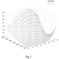
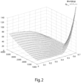
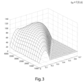
- the operating state is determined by Figures 1 to 3
- Figures 1 to 3 A diagram is shown for each of these, which shows the relationship between the power consumption P or the pressure increase ⁇ p st (static pressure) and the efficiency ⁇ st as well as the volume flow V and the speed n of an exemplary fan from the group of fans.
- n, V, P, ⁇ p st and ⁇ st represent detectable operating states or values correlating to them, which in the control procedures can be used.
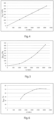
- the Figure 5 shows a diagram which shows the optimization potential of the static pressure ⁇ p opt depending on the speed n of a fan and the Fig.6 shows the optimization potential of the efficiency ⁇ opt in % depending on the speed n of a fan.
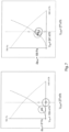
- the Fig. 7 shows a comparison of two states of a fan at a constant volume flow in the system, where the static pressure in the system has been reduced in order to increase the pressure supply ⁇ p st for the fan in order to increase the efficiency, as shown in the right figure.
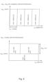
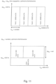
- the individual fans operate optimally at the operating point with a volume flow V of 10,000m 3 /h at 500Pa.
- An operating point with a volume flow V of 40,000m 3 /h at 500Pa can be achieved with 6, 5 or 4 fans in parallel operation.
Landscapes
- Engineering & Computer Science (AREA)
- Mechanical Engineering (AREA)
- General Engineering & Computer Science (AREA)
- Physics & Mathematics (AREA)
- Fluid Mechanics (AREA)
- Chemical & Material Sciences (AREA)
- Combustion & Propulsion (AREA)
- Control Of Positive-Displacement Air Blowers (AREA)
- Structures Of Non-Positive Displacement Pumps (AREA)
Claims (10)
- Procédé permettant de régler un système composé d'un nombre n d'au moins deux ventilateurs (1) et/ou de groupes de ventilateurs pour générer une valeur de consigne définie (VG,soll, ΔpG,soll), d'un débit volumique défini VG,soll dans le système avec une augmentation de pression ΔpG,Soll variable, ou inversement, comprenant les étapes suivantes consistant à :a) déterminer un état de fonctionnement des ventilateurs (1) ;b) déterminer un potentiel d'optimisation énergétique et un état de fonctionnement optimisé du et/ou des ventilateurs (1) respectifs ;c) comparer l'état de fonctionnement déterminé à l'étape a) avec l'état de fonctionnement respectivement optimisé du et/ou des ventilateurs (1) de l'étape b) pour obtenir une recommandation d'optimisation relative à un ventilateur (1), etd) corriger la valeur de consigne (VG,Soll, ΔpG,Soll) respectivement variable en modifiant le point de fonctionnement d'au moins un ventilateur (1) en fonction de la valeur de consigne qui est prédéfinie de manière fixe afin d'amener au moins l'un des ventilateurs (1) à un point de fonctionnement optimisé ou optimal sur le plan énergétique et d'augmenter ainsi le rendement ηG du système,dans lequel, à l'étape a), la détermination de l'état de fonctionnement des ventilateurs (1) est effectuée en ce qu'au moins un débit volumique V et une vitesse de rotation n du ventilateur (1) respectif et leur augmentation de pression Δpst, puissance absorbée P et rendement ηG sont déterminés en fonction du débit volumique et de la vitesse de rotation qui sont de préférence sauvegardés dans l'électronique du moteur de la pluralité de ventilateurs (1), etdans lequel, lors de la détermination de la recommandation d'optimisation pour l'adaptation de l'état de fonctionnement à l'étape c), on tient compte du ventilateur (1) qui possède une contribution à la puissance respectivement la plus élevée lors d'un refoulement d'air dans le système.
- Procédé selon la revendication 1, caractérisé en ce que l'étape d) est exécutée de telle sorte qu'une pluralité, un ou plusieurs sous-ensembles de ventilateurs ou tous les ventilateurs (1) sont amenés à un point de fonctionnement optimisé ou optimal sur le plan énergétique par rapport au point de fonctionnement non corrigé.
- Procédé selon la revendication 1 ou 2, caractérisé en ce que, un ou plusieurs ventilateurs (1) sont déconnectés à une valeur de consigne définie (VG,soll, ΔpG,soll) pour augmenter le rendement ηG du système.
- Procédé selon la revendication 1, caractérisé en ce que l'augmentation de pression Δpst et la puissance absorbée P du ventilateur (1) respectif sont déterminés à partir de son débit volumique V et de sa vitesse de rotation n.
- Procédé selon l'une quelconque des revendications précédentes, dans lequel, pour la détermination du potentiel d'optimisation à l'étape b), un débit volumique optimisé Vopt et une augmentation de pression optimisée Δpopt sont déterminés.
- Procédé selon l'une quelconque des revendications précédentes, dans lequel, à partir de la comparaison des états de fonctionnement de l'étape a) et de l'étape b), une recommandation d'optimisation sous la forme d'une adaptation de l'état de fonctionnement actuel d'un ou de plusieurs des ventilateurs (1) est effectuée, dans lequela) la recommandation d'optimisation à un débit volumique défini VG,Soll à maintenir constant consiste à procéder à une augmentation ou à une baisse de pression en fonction du fait que l'augmentation de pression optimisée Δpopt est supérieure ou inférieure à l'augmentation de pression déterminée Δpst, oub) la recommandation d'optimisation à une pression définie pG,Soll à maintenir constante consiste à augmenter ou à réduire le débit volumique en fonction du fait que le débit volumique optimisé Vopt est supérieur ou inférieur au débit volumique V déterminé.
- Procédé selon l'une quelconque des revendications précédentes, dans lequel la détection de la puissance absorbée P de chaque ventilateur (1) est effectuée respectivement avant ou après une correction à l'étape d), et il est déterminé si la somme totale de toutes les puissances absorbées P des ventilateurs (1) a été réduite en réponse à l'étape d'optimisation par rapport à la somme totale de toutes les puissances absorbées P, déterminée précédemment.
- Procédé selon la revendication 7, dans lequel, au cas où la somme totale de toutes les puissances absorbée P n'a pas été réduite après l'étape d'optimisation, l'adaptation est annulée au cours de l'étape d'optimisation effectuée précédemment.
- Procédé selon les revendications 6 à 8, dans lequel les mesures selon les revendications 6 à 8 sont répétées de manière cyclique jusqu'à obtenir un rendement total défini ou un rendement total respectivement optimisé par rapport au cycle précédent, dans lequel les mesures sont abandonnées au plus tard après un nombre défini de cycles.
- Dispositif de régulation (1) permettant d'exécuter un procédé selon l'une quelconque des revendications 1 à 9, dans lequel le dispositif de régulation présente :a) des moyens de détection pour déterminer le débit volumique de ventilateurs individuels et/ou de tous les ventilateurs (1) ;b) déterminer un potentiel d'optimisation énergétique Vopt et Δpst,opt et un état de fonctionnement optimisé des ventilateurs (1) respectifs qui peuvent être atteints avec la vitesse de rotation n à vitesse de rotation constante ;c) un comparateur pour comparer des états de fonctionnement déterminés et des états de fonctionnement optimisés afin d'en obtenir une recommandation d'optimisation spécifique ;d) des moyens pour adapter la valeur de consigne respectivement variable en modifiant l'état de fonctionnement d'au moins un ventilateur (1) en fonction de la valeur de consigne qui est prédéfinie de manière fixe dans le système afin d'amener au moins l'un des ventilateurs (1) à un point de fonctionnement optimisé ou optimal sur le plan énergétique et augmenter ainsi le rendement ηG du système.
Applications Claiming Priority (2)
| Application Number | Priority Date | Filing Date | Title |
|---|---|---|---|
| DE102017116399.9A DE102017116399A1 (de) | 2017-07-20 | 2017-07-20 | Verfahren zum Regeln von wenigstens zwei Ventilatoren |
| PCT/EP2018/068886 WO2019016056A1 (fr) | 2017-07-20 | 2018-07-12 | Procédé de réglage d'au moins deux ventilateurs |
Publications (2)
| Publication Number | Publication Date |
|---|---|
| EP3655663A1 EP3655663A1 (fr) | 2020-05-27 |
| EP3655663B1 true EP3655663B1 (fr) | 2024-10-09 |
Family
ID=62916661
Family Applications (1)
| Application Number | Title | Priority Date | Filing Date |
|---|---|---|---|
| EP18740797.8A Active EP3655663B1 (fr) | 2017-07-20 | 2018-07-12 | Procédé de réglage d'au moins deux ventilateurs |
Country Status (5)
| Country | Link |
|---|---|
| US (1) | US11486407B2 (fr) |
| EP (1) | EP3655663B1 (fr) |
| CN (1) | CN110832206B (fr) |
| DE (1) | DE102017116399A1 (fr) |
| WO (1) | WO2019016056A1 (fr) |
Families Citing this family (6)
| Publication number | Priority date | Publication date | Assignee | Title |
|---|---|---|---|---|
| EP3957921B1 (fr) * | 2019-04-15 | 2024-12-11 | Daikin Industries, Ltd. | Système de climatisation |
| AU2020261812B2 (en) | 2019-04-15 | 2022-12-22 | Daikin Industries, Ltd. | Air supply system |
| WO2020213216A1 (fr) * | 2019-04-15 | 2020-10-22 | ダイキン工業株式会社 | Système de conditionnement d'air |
| JP6761890B1 (ja) | 2019-04-15 | 2020-09-30 | ダイキン工業株式会社 | 空気調和システム |
| DE102022207457A1 (de) * | 2022-07-21 | 2024-02-01 | Robert Bosch Gesellschaft mit beschränkter Haftung | Gewichtete relative Lastverteilung einer n-Lüfter-Matrix zur Kühlung von Radiatoren |
| SE2251482A1 (en) * | 2022-12-16 | 2024-05-14 | Munters Italy S P A | A method for controlling a ventilation system |
Family Cites Families (13)
| Publication number | Priority date | Publication date | Assignee | Title |
|---|---|---|---|---|
| GB2134646B (en) | 1983-01-24 | 1986-08-28 | Howden James & Co Ltd | Surface mine ventilation system |
| US6227961B1 (en) * | 1998-05-21 | 2001-05-08 | General Electric Company | HVAC custom control system |
| KR100736944B1 (ko) * | 2003-03-20 | 2007-07-09 | 헌트에어 인코포레이션 | 공기 취급 시스템의 팬 섹션 팬 배열 |
| US7137775B2 (en) * | 2003-03-20 | 2006-11-21 | Huntair Inc. | Fan array fan section in air-handling systems |
| CN100354530C (zh) * | 2004-12-21 | 2007-12-12 | 英业达股份有限公司 | 一种串行风扇组及其转速匹配曲线产生方法 |
| US8326464B2 (en) | 2008-08-29 | 2012-12-04 | Trane International Inc. | Return fan control system and method |
| DE102008051199A1 (de) * | 2008-10-14 | 2010-04-29 | Maamar Bouchareb | Verfahren und Anordnung zur Lüfteransteuerung |
| WO2011056319A2 (fr) * | 2009-10-27 | 2011-05-12 | Huntair, Inc. | Système de commande de groupement de ventilateurs |
| US10138901B2 (en) * | 2011-03-21 | 2018-11-27 | Nortek Air Solutions, Llc | Systems and methods for implementing a fan array with quick connect and modular control |
| CN104460902B (zh) * | 2014-11-28 | 2017-09-19 | 华为技术有限公司 | 一种优化功率的风扇调控方法及装置 |
| US11041500B2 (en) * | 2015-09-22 | 2021-06-22 | International Business Machines Corporation | Parallel-series hybrid fan cooling apparatus and optimization |
| DE202016103978U1 (de) * | 2016-07-21 | 2016-08-05 | Ebm-Papst Mulfingen Gmbh & Co. Kg | Ventilatorgruppe |
| DE102016113496A1 (de) * | 2016-07-21 | 2018-01-25 | Ebm-Papst Mulfingen Gmbh & Co. Kg | Verfahren zum Regeln von Ventilatoren sowie Ventilatorgruppe |
-
2017
- 2017-07-20 DE DE102017116399.9A patent/DE102017116399A1/de active Pending
-
2018
- 2018-07-12 WO PCT/EP2018/068886 patent/WO2019016056A1/fr not_active Ceased
- 2018-07-12 EP EP18740797.8A patent/EP3655663B1/fr active Active
- 2018-07-12 CN CN201880044287.4A patent/CN110832206B/zh active Active
- 2018-07-12 US US16/623,865 patent/US11486407B2/en active Active
Also Published As
| Publication number | Publication date |
|---|---|
| EP3655663A1 (fr) | 2020-05-27 |
| WO2019016056A1 (fr) | 2019-01-24 |
| DE102017116399A1 (de) | 2019-01-24 |
| CN110832206B (zh) | 2021-08-27 |
| US11486407B2 (en) | 2022-11-01 |
| US20200340485A1 (en) | 2020-10-29 |
| CN110832206A (zh) | 2020-02-21 |
Similar Documents
| Publication | Publication Date | Title |
|---|---|---|
| EP3655663B1 (fr) | Procédé de réglage d'au moins deux ventilateurs | |
| EP2573400B1 (fr) | Procédé de commande d'une installation de compresseurs | |
| EP3940244B1 (fr) | Système et procédé de régulation optimisée d'un ensemble de ventilateurs multiples | |
| EP2579112B1 (fr) | Dispositif de régulation | |
| DE102016113496A1 (de) | Verfahren zum Regeln von Ventilatoren sowie Ventilatorgruppe | |
| EP0428948B1 (fr) | Procédé pour la récupération d'énergie dans des installations d'aération | |
| DE202017104349U1 (de) | Vorrichtung zum Regeln von wenigstens zwei Ventilatoren | |
| EP3647899A1 (fr) | Procédé de fonctionnement d'une soupape, unité de commande électronique associée et entraînement de soupape | |
| WO2000059678A1 (fr) | Procede et dispositif de meulage pour bande metallique laminee | |
| DE102014016349B4 (de) | Verfahren zum Herstellen und Betreiben einer industriellen Maschine oder Anlage | |
| DE202016103978U1 (de) | Ventilatorgruppe | |
| EP2947325B1 (fr) | Procédé de commande de pompe | |
| EP3320216B1 (fr) | Dispositif de simulation et procédé de simulation | |
| DE102004029790B4 (de) | Verfahren und Vorrichtung zum Optimieren von Reglerparametern | |
| EP3083032B1 (fr) | Procédé d'exploitation d'une installation de production de structure modulaire | |
| EP0587043A2 (fr) | Procédé et arrangement pour contrôle et régulation d'un générateur de pression pour plusieurs utilisateurs différents et hydrauliques branchés en parallèle | |
| DE102022208574A1 (de) | Verfahren zum Betreiben eines hydraulischen Antriebs einer Maschine und hydraulischer Antrieb | |
| DE102010056301A1 (de) | Verfahren zur automatischen Optimierung eines Heizsystems sowie Heizsystem | |
| EP2226500A2 (fr) | Régulateur de parc éolien | |
| EP4505080B1 (fr) | Procédé de réglage d'une alimentation en moyen de pression pour au moins un actionneur hydraulique, et système hydraulique | |
| DE102019208146A1 (de) | Fördereinrichtung, Verfahren sowie System | |
| DE19827447C1 (de) | Anordnung zur Klimatisierung von Räumen | |
| EP3480529A1 (fr) | Procédé de climatisation des unités d'espace d'un bâtiment | |
| DE10313437A1 (de) | Brennstoffzellensystem und Verfahren zur Steuerung der Energieflüsse in einem Brennstoffzellensystem | |
| WO2026092807A1 (fr) | Procédé de commande de système de ventilation, système de ventilation et installation comportant un tel système de ventilation |
Legal Events
| Date | Code | Title | Description |
|---|---|---|---|
| STAA | Information on the status of an ep patent application or granted ep patent |
Free format text: STATUS: UNKNOWN |
|
| STAA | Information on the status of an ep patent application or granted ep patent |
Free format text: STATUS: THE INTERNATIONAL PUBLICATION HAS BEEN MADE |
|
| PUAI | Public reference made under article 153(3) epc to a published international application that has entered the european phase |
Free format text: ORIGINAL CODE: 0009012 |
|
| STAA | Information on the status of an ep patent application or granted ep patent |
Free format text: STATUS: REQUEST FOR EXAMINATION WAS MADE |
|
| 17P | Request for examination filed |
Effective date: 20191119 |
|
| AK | Designated contracting states |
Kind code of ref document: A1 Designated state(s): AL AT BE BG CH CY CZ DE DK EE ES FI FR GB GR HR HU IE IS IT LI LT LU LV MC MK MT NL NO PL PT RO RS SE SI SK SM TR |
|
| AX | Request for extension of the european patent |
Extension state: BA ME |
|
| DAV | Request for validation of the european patent (deleted) | ||
| DAX | Request for extension of the european patent (deleted) | ||
| STAA | Information on the status of an ep patent application or granted ep patent |
Free format text: STATUS: EXAMINATION IS IN PROGRESS |
|
| 17Q | First examination report despatched |
Effective date: 20220920 |
|
| GRAP | Despatch of communication of intention to grant a patent |
Free format text: ORIGINAL CODE: EPIDOSNIGR1 |
|
| STAA | Information on the status of an ep patent application or granted ep patent |
Free format text: STATUS: GRANT OF PATENT IS INTENDED |
|
| RIC1 | Information provided on ipc code assigned before grant |
Ipc: F24F 11/74 20180101ALI20240417BHEP Ipc: F04D 27/00 20060101ALI20240417BHEP Ipc: F04D 25/16 20060101AFI20240417BHEP |
|
| INTG | Intention to grant announced |
Effective date: 20240513 |
|
| P01 | Opt-out of the competence of the unified patent court (upc) registered |
Free format text: CASE NUMBER: APP_42834/2024 Effective date: 20240722 |
|
| GRAS | Grant fee paid |
Free format text: ORIGINAL CODE: EPIDOSNIGR3 |
|
| GRAA | (expected) grant |
Free format text: ORIGINAL CODE: 0009210 |
|
| STAA | Information on the status of an ep patent application or granted ep patent |
Free format text: STATUS: THE PATENT HAS BEEN GRANTED |
|
| AK | Designated contracting states |
Kind code of ref document: B1 Designated state(s): AL AT BE BG CH CY CZ DE DK EE ES FI FR GB GR HR HU IE IS IT LI LT LU LV MC MK MT NL NO PL PT RO RS SE SI SK SM TR |
|
| REG | Reference to a national code |
Ref country code: CH Ref legal event code: EP |
|
| REG | Reference to a national code |
Ref country code: DE Ref legal event code: R096 Ref document number: 502018015210 Country of ref document: DE |
|
| REG | Reference to a national code |
Ref country code: IE Ref legal event code: FG4D Free format text: LANGUAGE OF EP DOCUMENT: GERMAN |
|
| REG | Reference to a national code |
Ref country code: NL Ref legal event code: FP |
|
| REG | Reference to a national code |
Ref country code: SE Ref legal event code: TRGR |
|
| REG | Reference to a national code |
Ref country code: LT Ref legal event code: MG9D |
|
| PG25 | Lapsed in a contracting state [announced via postgrant information from national office to epo] |
Ref country code: IS Free format text: LAPSE BECAUSE OF FAILURE TO SUBMIT A TRANSLATION OF THE DESCRIPTION OR TO PAY THE FEE WITHIN THE PRESCRIBED TIME-LIMIT Effective date: 20250209 Ref country code: HR Free format text: LAPSE BECAUSE OF FAILURE TO SUBMIT A TRANSLATION OF THE DESCRIPTION OR TO PAY THE FEE WITHIN THE PRESCRIBED TIME-LIMIT Effective date: 20241009 Ref country code: PT Free format text: LAPSE BECAUSE OF FAILURE TO SUBMIT A TRANSLATION OF THE DESCRIPTION OR TO PAY THE FEE WITHIN THE PRESCRIBED TIME-LIMIT Effective date: 20250210 |
|
| PG25 | Lapsed in a contracting state [announced via postgrant information from national office to epo] |
Ref country code: FI Free format text: LAPSE BECAUSE OF FAILURE TO SUBMIT A TRANSLATION OF THE DESCRIPTION OR TO PAY THE FEE WITHIN THE PRESCRIBED TIME-LIMIT Effective date: 20241009 |
|
| PG25 | Lapsed in a contracting state [announced via postgrant information from national office to epo] |
Ref country code: BG Free format text: LAPSE BECAUSE OF FAILURE TO SUBMIT A TRANSLATION OF THE DESCRIPTION OR TO PAY THE FEE WITHIN THE PRESCRIBED TIME-LIMIT Effective date: 20241009 |
|
| PG25 | Lapsed in a contracting state [announced via postgrant information from national office to epo] |
Ref country code: ES Free format text: LAPSE BECAUSE OF FAILURE TO SUBMIT A TRANSLATION OF THE DESCRIPTION OR TO PAY THE FEE WITHIN THE PRESCRIBED TIME-LIMIT Effective date: 20241009 |
|
| PG25 | Lapsed in a contracting state [announced via postgrant information from national office to epo] |
Ref country code: NO Free format text: LAPSE BECAUSE OF FAILURE TO SUBMIT A TRANSLATION OF THE DESCRIPTION OR TO PAY THE FEE WITHIN THE PRESCRIBED TIME-LIMIT Effective date: 20250109 |
|
| PG25 | Lapsed in a contracting state [announced via postgrant information from national office to epo] |
Ref country code: GR Free format text: LAPSE BECAUSE OF FAILURE TO SUBMIT A TRANSLATION OF THE DESCRIPTION OR TO PAY THE FEE WITHIN THE PRESCRIBED TIME-LIMIT Effective date: 20250110 Ref country code: LV Free format text: LAPSE BECAUSE OF FAILURE TO SUBMIT A TRANSLATION OF THE DESCRIPTION OR TO PAY THE FEE WITHIN THE PRESCRIBED TIME-LIMIT Effective date: 20241009 |
|
| PG25 | Lapsed in a contracting state [announced via postgrant information from national office to epo] |
Ref country code: PL Free format text: LAPSE BECAUSE OF FAILURE TO SUBMIT A TRANSLATION OF THE DESCRIPTION OR TO PAY THE FEE WITHIN THE PRESCRIBED TIME-LIMIT Effective date: 20241009 |
|
| PG25 | Lapsed in a contracting state [announced via postgrant information from national office to epo] |
Ref country code: RS Free format text: LAPSE BECAUSE OF FAILURE TO SUBMIT A TRANSLATION OF THE DESCRIPTION OR TO PAY THE FEE WITHIN THE PRESCRIBED TIME-LIMIT Effective date: 20250109 |
|
| PG25 | Lapsed in a contracting state [announced via postgrant information from national office to epo] |
Ref country code: SM Free format text: LAPSE BECAUSE OF FAILURE TO SUBMIT A TRANSLATION OF THE DESCRIPTION OR TO PAY THE FEE WITHIN THE PRESCRIBED TIME-LIMIT Effective date: 20241009 |
|
| PG25 | Lapsed in a contracting state [announced via postgrant information from national office to epo] |
Ref country code: DK Free format text: LAPSE BECAUSE OF FAILURE TO SUBMIT A TRANSLATION OF THE DESCRIPTION OR TO PAY THE FEE WITHIN THE PRESCRIBED TIME-LIMIT Effective date: 20241009 |
|
| REG | Reference to a national code |
Ref country code: DE Ref legal event code: R097 Ref document number: 502018015210 Country of ref document: DE |
|
| PG25 | Lapsed in a contracting state [announced via postgrant information from national office to epo] |
Ref country code: EE Free format text: LAPSE BECAUSE OF FAILURE TO SUBMIT A TRANSLATION OF THE DESCRIPTION OR TO PAY THE FEE WITHIN THE PRESCRIBED TIME-LIMIT Effective date: 20241009 |
|
| PG25 | Lapsed in a contracting state [announced via postgrant information from national office to epo] |
Ref country code: RO Free format text: LAPSE BECAUSE OF FAILURE TO SUBMIT A TRANSLATION OF THE DESCRIPTION OR TO PAY THE FEE WITHIN THE PRESCRIBED TIME-LIMIT Effective date: 20241009 |
|
| PG25 | Lapsed in a contracting state [announced via postgrant information from national office to epo] |
Ref country code: SK Free format text: LAPSE BECAUSE OF FAILURE TO SUBMIT A TRANSLATION OF THE DESCRIPTION OR TO PAY THE FEE WITHIN THE PRESCRIBED TIME-LIMIT Effective date: 20241009 |
|
| PG25 | Lapsed in a contracting state [announced via postgrant information from national office to epo] |
Ref country code: CZ Free format text: LAPSE BECAUSE OF FAILURE TO SUBMIT A TRANSLATION OF THE DESCRIPTION OR TO PAY THE FEE WITHIN THE PRESCRIBED TIME-LIMIT Effective date: 20241009 |
|
| PLBE | No opposition filed within time limit |
Free format text: ORIGINAL CODE: 0009261 |
|
| STAA | Information on the status of an ep patent application or granted ep patent |
Free format text: STATUS: NO OPPOSITION FILED WITHIN TIME LIMIT |
|
| PGFP | Annual fee paid to national office [announced via postgrant information from national office to epo] |
Ref country code: NL Payment date: 20250723 Year of fee payment: 8 |
|
| 26N | No opposition filed |
Effective date: 20250710 |
|
| PGFP | Annual fee paid to national office [announced via postgrant information from national office to epo] |
Ref country code: DE Payment date: 20250722 Year of fee payment: 8 |
|
| PGFP | Annual fee paid to national office [announced via postgrant information from national office to epo] |
Ref country code: TR Payment date: 20250707 Year of fee payment: 8 Ref country code: IT Payment date: 20250731 Year of fee payment: 8 |
|
| PGFP | Annual fee paid to national office [announced via postgrant information from national office to epo] |
Ref country code: GB Payment date: 20250724 Year of fee payment: 8 |
|
| PGFP | Annual fee paid to national office [announced via postgrant information from national office to epo] |
Ref country code: FR Payment date: 20250723 Year of fee payment: 8 Ref country code: AT Payment date: 20250721 Year of fee payment: 8 |
|
| PGFP | Annual fee paid to national office [announced via postgrant information from national office to epo] |
Ref country code: SE Payment date: 20250723 Year of fee payment: 8 |
|
| REG | Reference to a national code |
Ref country code: CH Ref legal event code: H13 Free format text: ST27 STATUS EVENT CODE: U-0-0-H10-H13 (AS PROVIDED BY THE NATIONAL OFFICE) Effective date: 20260224 |
|
| PG25 | Lapsed in a contracting state [announced via postgrant information from national office to epo] |
Ref country code: LU Free format text: LAPSE BECAUSE OF NON-PAYMENT OF DUE FEES Effective date: 20250712 |
|
| REG | Reference to a national code |
Ref country code: BE Ref legal event code: MM Effective date: 20250731 |
|
| PG25 | Lapsed in a contracting state [announced via postgrant information from national office to epo] |
Ref country code: BE Free format text: LAPSE BECAUSE OF NON-PAYMENT OF DUE FEES Effective date: 20250731 |
|
| PG25 | Lapsed in a contracting state [announced via postgrant information from national office to epo] |
Ref country code: CH Free format text: LAPSE BECAUSE OF NON-PAYMENT OF DUE FEES Effective date: 20250731 |