EP2376796B1 - Bague de retenue conique pour réduire le mouvement de la cage de roulement - Google Patents
Bague de retenue conique pour réduire le mouvement de la cage de roulement Download PDFInfo
- Publication number
- EP2376796B1 EP2376796B1 EP10729446.4A EP10729446A EP2376796B1 EP 2376796 B1 EP2376796 B1 EP 2376796B1 EP 10729446 A EP10729446 A EP 10729446A EP 2376796 B1 EP2376796 B1 EP 2376796B1
- Authority
- EP
- European Patent Office
- Prior art keywords
- shaft
- isolator
- component
- groove
- assembly
- Prior art date
- Legal status (The legal status is an assumption and is not a legal conclusion. Google has not performed a legal analysis and makes no representation as to the accuracy of the status listed.)
- Active
Links
- 230000007704 transition Effects 0.000 claims description 4
- 230000005540 biological transmission Effects 0.000 description 5
- 230000000295 complement effect Effects 0.000 description 4
- 230000004913 activation Effects 0.000 description 2
- 230000000712 assembly Effects 0.000 description 2
- 238000000429 assembly Methods 0.000 description 2
- 238000004519 manufacturing process Methods 0.000 description 2
- 230000009467 reduction Effects 0.000 description 2
- 238000005096 rolling process Methods 0.000 description 2
- 230000004323 axial length Effects 0.000 description 1
- 238000005452 bending Methods 0.000 description 1
- 230000008859 change Effects 0.000 description 1
- 230000001419 dependent effect Effects 0.000 description 1
- 238000009434 installation Methods 0.000 description 1
- 230000013011 mating Effects 0.000 description 1
- 238000012986 modification Methods 0.000 description 1
- 230000004048 modification Effects 0.000 description 1
Images



Classifications
-
- F—MECHANICAL ENGINEERING; LIGHTING; HEATING; WEAPONS; BLASTING
- F16—ENGINEERING ELEMENTS AND UNITS; GENERAL MEASURES FOR PRODUCING AND MAINTAINING EFFECTIVE FUNCTIONING OF MACHINES OR INSTALLATIONS; THERMAL INSULATION IN GENERAL
- F16C—SHAFTS; FLEXIBLE SHAFTS; ELEMENTS OR CRANKSHAFT MECHANISMS; ROTARY BODIES OTHER THAN GEARING ELEMENTS; BEARINGS
- F16C35/00—Rigid support of bearing units; Housings, e.g. caps, covers
- F16C35/04—Rigid support of bearing units; Housings, e.g. caps, covers in the case of ball or roller bearings
- F16C35/06—Mounting or dismounting of ball or roller bearings; Fixing them onto shaft or in housing
- F16C35/063—Fixing them on the shaft
-
- F—MECHANICAL ENGINEERING; LIGHTING; HEATING; WEAPONS; BLASTING
- F16—ENGINEERING ELEMENTS AND UNITS; GENERAL MEASURES FOR PRODUCING AND MAINTAINING EFFECTIVE FUNCTIONING OF MACHINES OR INSTALLATIONS; THERMAL INSULATION IN GENERAL
- F16C—SHAFTS; FLEXIBLE SHAFTS; ELEMENTS OR CRANKSHAFT MECHANISMS; ROTARY BODIES OTHER THAN GEARING ELEMENTS; BEARINGS
- F16C35/00—Rigid support of bearing units; Housings, e.g. caps, covers
- F16C35/04—Rigid support of bearing units; Housings, e.g. caps, covers in the case of ball or roller bearings
- F16C35/06—Mounting or dismounting of ball or roller bearings; Fixing them onto shaft or in housing
- F16C35/07—Fixing them on the shaft or housing with interposition of an element
- F16C35/073—Fixing them on the shaft or housing with interposition of an element between shaft and inner race ring
-
- F—MECHANICAL ENGINEERING; LIGHTING; HEATING; WEAPONS; BLASTING
- F16—ENGINEERING ELEMENTS AND UNITS; GENERAL MEASURES FOR PRODUCING AND MAINTAINING EFFECTIVE FUNCTIONING OF MACHINES OR INSTALLATIONS; THERMAL INSULATION IN GENERAL
- F16C—SHAFTS; FLEXIBLE SHAFTS; ELEMENTS OR CRANKSHAFT MECHANISMS; ROTARY BODIES OTHER THAN GEARING ELEMENTS; BEARINGS
- F16C17/00—Sliding-contact bearings for exclusively rotary movement
-
- F—MECHANICAL ENGINEERING; LIGHTING; HEATING; WEAPONS; BLASTING
- F16—ENGINEERING ELEMENTS AND UNITS; GENERAL MEASURES FOR PRODUCING AND MAINTAINING EFFECTIVE FUNCTIONING OF MACHINES OR INSTALLATIONS; THERMAL INSULATION IN GENERAL
- F16C—SHAFTS; FLEXIBLE SHAFTS; ELEMENTS OR CRANKSHAFT MECHANISMS; ROTARY BODIES OTHER THAN GEARING ELEMENTS; BEARINGS
- F16C17/00—Sliding-contact bearings for exclusively rotary movement
- F16C17/04—Sliding-contact bearings for exclusively rotary movement for axial load only
- F16C17/08—Sliding-contact bearings for exclusively rotary movement for axial load only for supporting the end face of a shaft or other member, e.g. footstep bearings
-
- F—MECHANICAL ENGINEERING; LIGHTING; HEATING; WEAPONS; BLASTING
- F16—ENGINEERING ELEMENTS AND UNITS; GENERAL MEASURES FOR PRODUCING AND MAINTAINING EFFECTIVE FUNCTIONING OF MACHINES OR INSTALLATIONS; THERMAL INSULATION IN GENERAL
- F16H—GEARING
- F16H57/00—General details of gearing
-
- F—MECHANICAL ENGINEERING; LIGHTING; HEATING; WEAPONS; BLASTING
- F16—ENGINEERING ELEMENTS AND UNITS; GENERAL MEASURES FOR PRODUCING AND MAINTAINING EFFECTIVE FUNCTIONING OF MACHINES OR INSTALLATIONS; THERMAL INSULATION IN GENERAL
- F16H—GEARING
- F16H57/00—General details of gearing
- F16H57/0018—Shaft assemblies for gearings
- F16H57/0031—Shaft assemblies for gearings with gearing elements rotatable supported on the shaft
-
- F—MECHANICAL ENGINEERING; LIGHTING; HEATING; WEAPONS; BLASTING
- F16—ENGINEERING ELEMENTS AND UNITS; GENERAL MEASURES FOR PRODUCING AND MAINTAINING EFFECTIVE FUNCTIONING OF MACHINES OR INSTALLATIONS; THERMAL INSULATION IN GENERAL
- F16B—DEVICES FOR FASTENING OR SECURING CONSTRUCTIONAL ELEMENTS OR MACHINE PARTS TOGETHER, e.g. NAILS, BOLTS, CIRCLIPS, CLAMPS, CLIPS OR WEDGES; JOINTS OR JOINTING
- F16B21/00—Means for preventing relative axial movement of a pin, spigot, shaft or the like and a member surrounding it; Stud-and-socket releasable fastenings
- F16B21/10—Means for preventing relative axial movement of a pin, spigot, shaft or the like and a member surrounding it; Stud-and-socket releasable fastenings by separate parts
- F16B21/16—Means for preventing relative axial movement of a pin, spigot, shaft or the like and a member surrounding it; Stud-and-socket releasable fastenings by separate parts with grooves or notches in the pin or shaft
- F16B21/18—Means for preventing relative axial movement of a pin, spigot, shaft or the like and a member surrounding it; Stud-and-socket releasable fastenings by separate parts with grooves or notches in the pin or shaft with circlips or like resilient retaining devices, i.e. resilient in the plane of the ring or the like; Details
- F16B21/186—Means for preventing relative axial movement of a pin, spigot, shaft or the like and a member surrounding it; Stud-and-socket releasable fastenings by separate parts with grooves or notches in the pin or shaft with circlips or like resilient retaining devices, i.e. resilient in the plane of the ring or the like; Details external, i.e. with contracting action
-
- F—MECHANICAL ENGINEERING; LIGHTING; HEATING; WEAPONS; BLASTING
- F16—ENGINEERING ELEMENTS AND UNITS; GENERAL MEASURES FOR PRODUCING AND MAINTAINING EFFECTIVE FUNCTIONING OF MACHINES OR INSTALLATIONS; THERMAL INSULATION IN GENERAL
- F16B—DEVICES FOR FASTENING OR SECURING CONSTRUCTIONAL ELEMENTS OR MACHINE PARTS TOGETHER, e.g. NAILS, BOLTS, CIRCLIPS, CLAMPS, CLIPS OR WEDGES; JOINTS OR JOINTING
- F16B2200/00—Constructional details of connections not covered for in other groups of this subclass
- F16B2200/69—Redundant disconnection blocking means
-
- F—MECHANICAL ENGINEERING; LIGHTING; HEATING; WEAPONS; BLASTING
- F16—ENGINEERING ELEMENTS AND UNITS; GENERAL MEASURES FOR PRODUCING AND MAINTAINING EFFECTIVE FUNCTIONING OF MACHINES OR INSTALLATIONS; THERMAL INSULATION IN GENERAL
- F16C—SHAFTS; FLEXIBLE SHAFTS; ELEMENTS OR CRANKSHAFT MECHANISMS; ROTARY BODIES OTHER THAN GEARING ELEMENTS; BEARINGS
- F16C2226/00—Joining parts; Fastening; Assembling or mounting parts
- F16C2226/50—Positive connections
-
- F—MECHANICAL ENGINEERING; LIGHTING; HEATING; WEAPONS; BLASTING
- F16—ENGINEERING ELEMENTS AND UNITS; GENERAL MEASURES FOR PRODUCING AND MAINTAINING EFFECTIVE FUNCTIONING OF MACHINES OR INSTALLATIONS; THERMAL INSULATION IN GENERAL
- F16C—SHAFTS; FLEXIBLE SHAFTS; ELEMENTS OR CRANKSHAFT MECHANISMS; ROTARY BODIES OTHER THAN GEARING ELEMENTS; BEARINGS
- F16C2361/00—Apparatus or articles in engineering in general
- F16C2361/61—Toothed gear systems, e.g. support of pinion shafts
-
- Y—GENERAL TAGGING OF NEW TECHNOLOGICAL DEVELOPMENTS; GENERAL TAGGING OF CROSS-SECTIONAL TECHNOLOGIES SPANNING OVER SEVERAL SECTIONS OF THE IPC; TECHNICAL SUBJECTS COVERED BY FORMER USPC CROSS-REFERENCE ART COLLECTIONS [XRACs] AND DIGESTS
- Y10—TECHNICAL SUBJECTS COVERED BY FORMER USPC
- Y10T—TECHNICAL SUBJECTS COVERED BY FORMER US CLASSIFICATION
- Y10T403/00—Joints and connections
- Y10T403/70—Interfitted members
- Y10T403/7047—Radially interposed shim or bushing
- Y10T403/7061—Resilient
Definitions
- the present disclosure is related to shaft assemblies having components mounted on a shaft and movable along the axis of the shaft. More specifically, the present disclosure is related to a shaft assembly having components mounted on the shaft that support radial and axial loads, the shaft configured so that the axial loads are transferred to the shaft.
- Tapered retaining rings are used to remove axial endplay of components mounted on a shaft through an external ring.
- Tapered internal rings may be used inside a bore to reduce the endplay of components within the bore.
- Endplay refers to the movement of components mounted on a shaft or in a bore. Such movement occurs when the axial lengths of the components vary within a tolerance band. The stack-up of the tolerances results in a difference between the length of the stacked components and the distance between retainers used to hold the stacked components together. Such a difference results in unwanted movement of one or more of the components parallel to the longitudinal axis of the shaft or bore.
- a shaft assembly within a transmission includes multiple components such as gears, clutches, and bearings.
- the components are mounted on the shaft and may have some freedom of movement along the shaft.
- An axial load is a load having a component parallel to the axis of the shaft.
- An axial load on one or more of the components tends to cause adjacent components to impart a force on one another.
- the axial load may cause movement in the adjacent components, such as bearings, for example. Variation in the endplay of a bearing may tend to reduce the life of the bearing through excess load and heat.
- FR 2 912 198 A1 describes a device that has a ring engaged in a circular groove of a transmission shaft and in a support against a speed gear and a lock washer in a manner to provide axial force of the gear on the shaft.
- the washer is mounted between the ring and an inner ring of a rolling bearing to immobilize the ring in rotation on the shaft and to retain the ring radially against the shaft without transmitting axial force of the gear to the rolling bearing.
- an assembly comprising a shaft defining a longitudinal axis, a first component supported on the shaft, a second component supported on the shaft, wherein the second component is selectively lockable to the shaft such that the assembly transitions between a first state in which the second component rotates about the shaft and a second state in which the second component is locked to the shaft and rotates with the shaft, wherein the second component is configured such that the second component induces a force having a component parallel to the axis of the shaft, and an isolator positioned between the first component and the second component such that the force component parallel to the axis of the shaft induced by the second component is transferred directly to the shaft by the isolator and is isolated from the first component, wherein the shaft defines a tapered groove and the isolator comprises a tapered retaining ring fully seated in the tapered groove.
- the groove can have a first surface generally perpendicular to the longitudinal axis of the shaft.
- the groove may also include a second tapered surface opposing the first surface and oblique to the axis of the shaft such that the first and second surfaces form a tapered groove.
- the isolator is removably engaged with the groove.
- the isolator may include a first face surface engaged with the first surface of the groove.
- the isolator may also include a second surface opposite the first surface. The second surface may be configured to engage a portion of the first component.
- the isolator may also include a tapered surface adjacent the second surface of the isolator, the tapered surface configured to engage the tapered surface of the groove.
- the isolator may be biased such that the tapered surface of the isolator is urged against the tapered surface of the groove to fully seat the isolator in the groove.
- the first component comprises a tapered roller bearing and the isolator positions the tapered roller bearing on the shaft.
- the second component comprises a helical gear.
- the helical gear may develop a thrust force parallel to the longitudinal axis of the shaft.
- the assembly includes:
- the isolator comprises a tapered retaining ring.
- the retaining ring include a tapered surface configured to engage a tapered surface of the groove in the shaft and the retaining ring is biased to urge the tapered surfaces together to seat the retaining ring in the groove.
- the first surface of the groove may be positioned such that when the isolator is seated in the groove, the first bearing is positioned on the shaft such that the spacing between an inner race and an outer race of the first bearing is within the design limits of the bearing.
- the isolator includes a tapered surface configured to engage a tapered surface of the groove. As the isolator includes the tapered surface, the isolator may be biased to urge the isolator into the groove to fully seat the isolator in the groove.
- a shaft assembly 12 shown in Fig. 1 is illustratively configured to be supported in a housing 26 (seen in Fig. 2 ).
- the shaft assembly 12 includes, for example, two tapered roller bearings 14 and 16 engaged with the housing 26 to support a shaft 22 of the shaft assembly 12 for rotation about a longitudinal axis 24 relative to the housing.
- the bearings 14 and 16 each include outer races 18 and 20 respectively which are illustratively press fit into the housing 26 as shown in the cross-sectional view shown in Fig. 2 .
- the shaft assembly 12 may be used in a multi-stage automatic transmission, for example.
- the helical gear 28 is coupled to a clutch assembly 30 which is operable to transition between a first state in which the gear 28 is free to rotate about the shaft 22 and a second state in which the gear 28 is locked to the shaft 22 to rotate with the shaft 22 about an axis 24 of the shaft 22.
- a second component 32 illustratively embodied as another helical gear, is coupled to a second clutch assembly 34.
- the clutch assembly 34 is operable to transition between a first state in which the gear 32 is free to rotate about the shaft 22 and a second state in which the gear 32 is locked to the shaft 22 and rotates with the shaft 22 about the axis 24.
- Yet another component 36 embodied as a helical gear is coupled to the shaft 22 and rotates with the shaft 22 about the axis 24.
- the gear 36 includes a plurality of internal splines 38 which are received on external splines 40 on the shaft 22 to transfer rotation of the shaft 22 to the gear 36.
- Gear 28 has a number of helical teeth 42 which are configured to mesh with mating teeth of a complementary gear (not shown) to transfer rotation between the gear 28 and the complementary gear.
- the gear 36 may receive torque from a complementary component. Because gear 36 is fixed to shaft 22, the torque is thereby transferred through gear 36 to shaft 22. Activation of clutch assembly 30 results in gear 28 being locked to shaft 22 such that torque is transferred from the shaft 22 to the gear 28.
- gear 28 has a diameter that is greater than the diameter of the gear 36. Rotation 36 having a smaller diameter than the larger gear 28 results in a lower output speed at the teeth of gear 28.
- gear 32 also has helical teeth 44 and gear 36 has teeth 46.
- activation of clutch 34 results in rotation being transferred from shaft 22 to gear 32.
- Gear 32 has a larger diameter than gear 28. The larger diameter of gear 32 results in an even lower output speed at the teeth 44 when gear 32 is driven by gear 36.
- shaft assembly 12 may be used in an automatic transmission to transfer between a low range output when clutch 34 is activated and a high range output when clutch 30 is activated.
- helical gear teeth such as the teeth 42, 44, and 46 of gears 28, 32, and 36 respectively results in reduced noise due to reduced impact as compared to a traditional straight-toothed spur gear.
- the helical aspect of the teeth 42, 44, and 46 results in a load being induced in the gears in a direction parallel to the axis of rotation of the gears 28, 32, and 36.
- the axis of rotation of the gears 28, 32 and 36 is coincident with the axis 24 of the shaft 22.
- the transfer of torque between the gears 28, 32, and 36 and complementary gears induces a force 48 to the teeth of the gears 28, 32 and 36 having a first force component 50 perpendicular to the axis 24 and a second force component 52 parallel to the axis 24 as illustrated in Fig. 3 .
- the second force component 52 is an incidental force that is a result of the use of a helical gear tooth profile.
- the magnitude of the incidental force component 52 will vary depending on the amount of torque being transferred and the angle of the helical teeth, among other things.
- the force perpendicular to shaft 22 is transferred through the shaft assembly 12 as torque is transferred.
- the incidental force component referred to hereinafter as a thrust load
- the thrust force 52 is transferred through the components supported on the shaft 22 until a reaction is supported in the assembly.
- the thrust load has been born by tapered roller bearings positioned at either end of a shaft assembly. Tapered roller bearings are configured to support both a thrust load as well as supporting a shaft for rotation.
- tapered roller bearing The selection of the appropriate size of tapered roller bearing is partially dependent upon the magnitude of the thrust load applied to the bearing. Excessive thrust load applied to the bearing induces losses in the assembly by increasing the normal load on the bearing components, thereby increasing the friction forces in the bearing. For example, if an inner race 56 of bearing 14 is movable on the shaft 22, endplay will be reduced and loads on the bearing 14 may increase. The losses are typically converted to heat which reduces the life of the bearing and the efficiency of the assembly.
- the thrust load 52 is not applied to the thrust bearings 14 and 16.
- the thrust load 52 is reacted to the shaft 22 by the use of an isolator 54, illustratively embodied as a retaining ring 54 secured to the shaft 22 and positioned to transfer the thrust load 52 directly to the shaft 22. While in the illustrative embodiment a retaining ring is used as an isolator, those of ordinary skill in the art will readily recognize that various components may be employed as the isolator within the scope of this disclosure.
- a circlip, a snap-ring, an e-ring, a radial grip ring, a crescent ring, a clipring or other similar product may form at least a portion of an isolator within the scope of this disclosure as described in more detail below.
- gear 28 is supported on a plurality of needle bearings 60 for rotation with respect to the shaft 22.
- the tapered roller bearing 14 is positioned with the outer race 18 engaged with the housing 26.
- a plurality of rollers 58 is positioned between the outer race 18 and an inner race 56 so that the races 18 and 56 may move relative to one another.
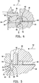
- the isolator, illustratively embodied as the retaining ring 54 is positioned adjacent the inner race 56 and is secured to the shaft 22 by engaging a groove 64 formed in the shaft 22.
- a thrust washer 62 is interposed between the retaining ring 54 and the gear 28 such that when the gear 28 rotates relative to the shaft 22, the thrust washer 62 acts as a bearing between the gear 28 and the retaining ring 54.
- the spacing between the inner race 56 and outer race 18 of bearing 14 is controlled so that the operation of the bearing 14 is optimized.
- groove 64 is positioned so that the retaining ring 54 engages the inner race 56 to control the position of the inner race 56 on the shaft 22.
- the retaining ring 54 is also positioned such that the thrust load 52 is received by the retaining ring 54 and not transferred directly to the inner race 56. This permits an appropriate endplay spacing between the races 56 and 18 to be maintained as designed in contrast to having the thrust load 52 applied to the inner race 56 which may tend to move the race 56 along the shaft 22 and change the spacing.
- retaining ring 54 positions the inner race 56 and isolates the inner race 56 from the thrust load 52.
- the groove 64 includes a wall 66 that is substantially perpendicular to the axis 24 of shaft 22.
- a second wall 70 opposing the wall 66 is at an angle oblique to the axis 24 of the shaft 22.
- a groove bottom 68 interconnects the walls 66 and 70.
- the retaining ring 54 is formed to include first and second face surfaces 78 and 72 respectively.
- An oblique surface 74 is formed along an inner periphery of the retaining ring 54 as shown in Fig. 6 . Referring again to Fig. 5 , when retaining ring 54 is positioned in the groove 64, the oblique surface 74 engages the surface 70 of the groove 64.
- the retaining ring 54 is biased in the direction of arrows 82 and 84 to the configuration shown in Fig. 6 .
- the bias of the retaining ring 54 causes the ring 54 to seat with the surfaces 78 and 74 of the retaining ring 54 engaged with the surfaces 66 and 70 of the groove 64, respectively.
- the groove would be produced with two parallel walls spaced apart by the thickness of the retaining ring. Manufacturing variances in the position between the walls and the thickness of the retaining ring may result in the retaining ring being movable in the groove along the axis of the shaft.
- a thrust load applied to the retaining ring would displace the retaining ring and transfer the thrust load through the retaining ring to an adjacent component, such as an inner race of a bearing, for example.
- the tapered retaining ring 54 seats against the surfaces 66 and 70 with some variation in the position of surface 70. Once the retaining ring 54 is seated it will not move along the axis 24 of the shaft 22.
- the retaining ring 54 acts as a rigid isolator between the thrust loaded gear 28 and the inner bearing race 56. The spacing of the bearing races 56 and 18 is maintained as designed and the thrust load 52 is reacted to the shaft 22 and not the bearing 14.
- retaining ring 54 includes a number of extensions 80 about the outer periphery of the retaining ring 54.
- the extensions 80 provide additional surface area to act against the bearing race 56 and the thrust washer 62 without increasing the rigidity of the retaining ring 54 when the retaining ring 54 is deflected to be placed on the shaft 22.
- the risk of damage to the retaining ring 54 is thereby reduced as the bending stress induced in the retaining ring 54 during installation is minimized.
- a retaining ring having a tapered surface on an outer periphery and extensions positioned on the inner periphery may be used in an internal bore to position components and isolate thrust forces in the bore.
- the use of the tapered aspect of the retaining ring to both position the retaining ring and permit the retaining ring to be fully seated to act as a thrust load isolator provides a reduction in manufacturing costs, improved reliability, and reduction in the cost of components by controlling the loading of the tapered roller bearings.
Landscapes
- Engineering & Computer Science (AREA)
- General Engineering & Computer Science (AREA)
- Mechanical Engineering (AREA)
- Mounting Of Bearings Or Others (AREA)
- General Details Of Gearings (AREA)
- Rolling Contact Bearings (AREA)
- Support Of The Bearing (AREA)
Claims (9)
- Ensemble (12) comprenant
un arbre (22) définissant un axe longitudinal (24),
un premier composant (28) supporté sur l'arbre (22),
un deuxième composant (32) supporté sur l'arbre (22),
où le deuxième composant (32) peut sélectivement être verrouillé sur l'arbre (22) de sorte que l'ensemble effectue une transition entre un premier état dans lequel le deuxième composant (32) tourne autour de l'arbre (22) et un deuxième état dans lequel le deuxième composant (32) est verrouillé sur l'arbre (22) et tourne avec l'arbre (22), où le deuxième composant (32) est configuré de sorte que le deuxième composant (32) induise une force ayant une composante parallèle à l'axe de l'arbre (22), et
un isolateur (54) positionné entre le premier composant (28) et le deuxième composant (32) de sorte que la composante de force parallèle à l'axe de l'arbre (22) induite par le deuxième composant (32) soit transférée directement à l'arbre (22) par l'isolateur (54) et soit isolée du premier composant (28),
caractérisé en ce que
l'arbre définit une rainure conique (64) et l'isolateur (54) comprend une bague de retenue conique (54) complètement placée dans la rainure conique (64). - Ensemble selon la revendication 1, la rainure comportant une première surface (66) globalement perpendiculaire à l'axe longitudinal de l'arbre et une deuxième surface (70) opposée à la première surface, la deuxième surface étant formée de manière oblique par rapport à l'axe longitudinal de l'arbre.
- Ensemble de la revendication 2, dans lequel l'isolateur est engagé de manière amovible avec la rainure.
- Ensemble de la revendication 3, dans lequel l'isolateur comporte une première surface frontale (78) engagée avec la première surface de la rainure et une deuxième surface (72) opposée à la première surface frontale, la deuxième surface de l'isolateur étant engagée avec la deuxième surface de la rainure.
- Ensemble de la revendication 4, dans lequel l'isolateur est sollicité pour pousser la deuxième surface de l'isolateur contre la deuxième surface de la rainure afin de placer complètement l'isolateur dans la rainure.
- Ensemble de la revendication 5, dans lequel le premier composant comprend un roulement à rouleaux coniques (14) et l'isolateur positionne le roulement à rouleaux coniques sur l'arbre.
- Ensemble de la revendication 6, dans lequel le deuxième composant comprend un engrenage hélicoïdal (28).
- Ensemble de la revendication 1, dans lequel l'ensemble comprend un premier roulement (14) supportant la première extrémité de l'arbre sur un boîtier, un deuxième roulement (16) supportant la deuxième extrémité de l'arbre sur le boîtier et l'isolateur positionne l'un des premier et deuxième roulements sur l'arbre.
- Ensemble (12) de la revendication 1 comprenant,
un logement (26),
un premier roulement (14) supportant la première extrémité de l'arbre sur le logement, et
un deuxième roulement (16) supportant la deuxième extrémité de l'arbre sur le logement,
où (i) la rainure conique comporte une première surface globalement perpendiculaire à l'axe longitudinal de l'arbre et une deuxième surface opposée à la première surface et formée de manière oblique par rapport à l'axe longitudinal de l'arbre, (ii) le deuxième composant est un engrenage hélicoïdal (32), (iii) l'isolateur est positionné dans la rainure conique entre le premier roulement et l'engrenage hélicoïdal de sorte qu'une force de poussée développée par l'engrenage hélicoïdal soit transférée par l'isolateur directement à l'arbre et soit isolée, par l'isolateur, du premier roulement, (iv) l'isolateur comporte une première surface frontale (78) engagée avec la première surface de la rainure et une deuxième surface (72) opposée à la première surface frontale qui est engagée avec la deuxième surface de la rainure, et (v) l'isolateur est engagé de manière amovible avec la rainure.
Applications Claiming Priority (2)
| Application Number | Priority Date | Filing Date | Title |
|---|---|---|---|
| US12/351,220 US8747014B2 (en) | 2009-01-09 | 2009-01-09 | Tapered retaining ring to reduce bearing race movement |
| PCT/US2010/020225 WO2010080807A1 (fr) | 2009-01-09 | 2010-01-06 | Bague de retenue conique pour réduire le mouvement de la cage de roulement |
Publications (3)
| Publication Number | Publication Date |
|---|---|
| EP2376796A1 EP2376796A1 (fr) | 2011-10-19 |
| EP2376796A4 EP2376796A4 (fr) | 2013-08-28 |
| EP2376796B1 true EP2376796B1 (fr) | 2017-09-20 |
Family
ID=42316781
Family Applications (1)
| Application Number | Title | Priority Date | Filing Date |
|---|---|---|---|
| EP10729446.4A Active EP2376796B1 (fr) | 2009-01-09 | 2010-01-06 | Bague de retenue conique pour réduire le mouvement de la cage de roulement |
Country Status (6)
| Country | Link |
|---|---|
| US (1) | US8747014B2 (fr) |
| EP (1) | EP2376796B1 (fr) |
| KR (1) | KR101638212B1 (fr) |
| CN (1) | CN102308104B (fr) |
| CA (1) | CA2749150C (fr) |
| WO (1) | WO2010080807A1 (fr) |
Families Citing this family (13)
| Publication number | Priority date | Publication date | Assignee | Title |
|---|---|---|---|---|
| EP2739881B2 (fr) * | 2011-08-05 | 2023-03-01 | Sew-Eurodrive GmbH & Co. KG | Roue dentée à denture oblique et segment pour une roue dentée |
| DE102012024425A1 (de) * | 2012-12-14 | 2014-06-18 | Getrag Getriebe- Und Zahnradfabrik Hermann Hagenmeyer Gmbh & Cie Kg | Scheibenanordnung für eine Axiallageranordnung |
| EP2980407B1 (fr) * | 2013-03-27 | 2019-06-26 | Hitachi-Johnson Controls Air Conditioning, Inc. | Compresseur à spirales |
| PL3161333T3 (pl) * | 2014-06-25 | 2020-03-31 | Gkn Driveline North America, Inc. | Ogranicznik do wałów wewnętrznych i zewnętrznych |
| CN108317180B (zh) * | 2018-01-15 | 2020-01-03 | 东南大学 | 转子实验台支承调位及轴承预紧装置 |
| EP3587819A1 (fr) * | 2018-06-29 | 2020-01-01 | Grundfos Holding A/S | Pompe |
| CN109210060A (zh) * | 2018-09-12 | 2019-01-15 | 福建龙溪轴承(集团)股份有限公司 | 一种弹性挡圈结构和一种内外套拆装结构 |
| CN109578554A (zh) * | 2018-12-19 | 2019-04-05 | 芜湖世特瑞转向系统有限公司 | 减速器输出轴消隙机构及电动助力转向系统用减速器 |
| US11525471B2 (en) * | 2019-08-28 | 2022-12-13 | GM Global Technology Operations LLC | Snap ring retention |
| DE102020106278A1 (de) * | 2020-03-09 | 2021-09-09 | Saurer Spinning Solutions Gmbh & Co. Kg | Vorrichtung zur Drehmomentübertragung |
| US11578760B1 (en) * | 2021-07-30 | 2023-02-14 | Rivian Ip Holdings, Llc | Input gear assembly with pilot regions on shaft and inner bearing race |
| CN115539588A (zh) * | 2022-09-30 | 2022-12-30 | 广州纽蓝客智能科技有限公司 | 一种防止轴承松动的防松结构及防松方法 |
| DE102024200639A1 (de) * | 2023-01-25 | 2024-07-25 | Dana Automotive Systems Group, Llc | Radnabensystem |
Family Cites Families (25)
| Publication number | Priority date | Publication date | Assignee | Title |
|---|---|---|---|---|
| BE469107A (fr) * | 1945-01-25 | |||
| US2595787A (en) * | 1947-03-12 | 1952-05-06 | Waldes Kohinoor Inc | Retaining ring assembly |
| US3017006A (en) * | 1959-10-01 | 1962-01-16 | Clark Equipment Co | Clutch mechanism |
| US4019824A (en) | 1976-02-03 | 1977-04-26 | Percy Vernon L | Positive ring retaining system |
| US4182578A (en) * | 1978-03-24 | 1980-01-08 | Caterpillar Tractor Co. | Keeper assembly |
| US4411346A (en) * | 1981-06-11 | 1983-10-25 | The Falk Corporation | Disc clutch apparatus |
| US4618190A (en) * | 1983-03-18 | 1986-10-21 | Caterpillar Inc. | Track joint retaining apparatus |
| DE3421188A1 (de) * | 1984-06-07 | 1985-12-12 | SKF GmbH, 8720 Schweinfurt | Befestigung eines waelzlagers in einem gehaeuse o.dgl. |
| FR2597560B1 (fr) * | 1986-04-18 | 1988-08-05 | Valeo | Montage de butee de debrayage, notamment pour vehicule automobile |
| US5061089A (en) | 1990-04-16 | 1991-10-29 | Eaton Corporation | Tapered bearing isolator |
| US5078510A (en) | 1990-08-27 | 1992-01-07 | Eaton Corporation | Bearing isolator |
| US5127764A (en) * | 1991-04-24 | 1992-07-07 | Shop Vac Corporation | Clip ring spread preventer |
| JPH07243450A (ja) | 1994-03-02 | 1995-09-19 | Daihatsu Motor Co Ltd | スラストワッシャの回り止め構造 |
| US5971621A (en) * | 1998-05-04 | 1999-10-26 | Ford Motor Company | Axial shaft retention design |
| US6390477B1 (en) | 1999-10-14 | 2002-05-21 | Garlock Inc | Rotary shaft bearing isolator seal |
| JP4474774B2 (ja) * | 2000-05-31 | 2010-06-09 | 日本精工株式会社 | 車輪駆動用ユニット |
| JP2005503518A (ja) * | 2001-03-12 | 2005-02-03 | ハンセン・トランスミッションズ・インターナショナル・ナムローゼフェンノートシャップ | 歯車軸の軸受組立体 |
| US20030070898A1 (en) | 2001-10-11 | 2003-04-17 | Eugene Wolbers | 3-D misalignment isolator bearing |
| KR100469463B1 (ko) * | 2002-09-10 | 2005-02-02 | 엘지전자 주식회사 | 왕복동식 압축기의 고정자 결합구조 |
| US7121632B2 (en) * | 2004-05-05 | 2006-10-17 | Gkn Driveline North Amercia, Inc. | Shaft and wheel hub retention assembly |
| FR2897404B1 (fr) | 2006-02-16 | 2009-02-27 | Renault Sas | Dispositif d'arret axial d'un pignon fou de boite de vitesses et procede de montage d'un tel dispositif |
| US20080078648A1 (en) | 2006-09-07 | 2008-04-03 | Orlowski David C | Bearing isolator and conveyor roller |
| JP2008202782A (ja) * | 2007-01-26 | 2008-09-04 | Jtekt Corp | 転がり軸受装置 |
| FR2912198B1 (fr) | 2007-02-07 | 2009-03-13 | Renault Sas | Dispositif d'arret axial d'un pignon fou sur un arbre de boite de vitesses et procede de montage de celui-ci |
| CN201027910Y (zh) * | 2007-04-11 | 2008-02-27 | 天津减速机股份有限公司 | 大传动比垂直输出减速机 |
-
2009
- 2009-01-09 US US12/351,220 patent/US8747014B2/en active Active
-
2010
- 2010-01-06 CA CA2749150A patent/CA2749150C/fr active Active
- 2010-01-06 KR KR1020117017663A patent/KR101638212B1/ko not_active Expired - Fee Related
- 2010-01-06 EP EP10729446.4A patent/EP2376796B1/fr active Active
- 2010-01-06 WO PCT/US2010/020225 patent/WO2010080807A1/fr not_active Ceased
- 2010-01-06 CN CN201080007048.5A patent/CN102308104B/zh active Active
Non-Patent Citations (1)
| Title |
|---|
| None * |
Also Published As
| Publication number | Publication date |
|---|---|
| CN102308104A (zh) | 2012-01-04 |
| EP2376796A1 (fr) | 2011-10-19 |
| CA2749150C (fr) | 2017-03-07 |
| US20100178103A1 (en) | 2010-07-15 |
| WO2010080807A1 (fr) | 2010-07-15 |
| US8747014B2 (en) | 2014-06-10 |
| KR20110117665A (ko) | 2011-10-27 |
| EP2376796A4 (fr) | 2013-08-28 |
| CA2749150A1 (fr) | 2010-07-15 |
| KR101638212B1 (ko) | 2016-07-08 |
| CN102308104B (zh) | 2016-02-17 |
Similar Documents
| Publication | Publication Date | Title |
|---|---|---|
| EP2376796B1 (fr) | Bague de retenue conique pour réduire le mouvement de la cage de roulement | |
| US8850911B2 (en) | Preload unit module | |
| US8409050B2 (en) | Gear retention assembly | |
| CN105008746B (zh) | 单向离合器支架组件 | |
| US20180187767A1 (en) | Power transmission system for vehicle | |
| EP1820981A2 (fr) | Roulement à rouleaux pour mécanisme d'un engrenage planétaire | |
| US7413067B2 (en) | Dog clutch | |
| KR102635371B1 (ko) | 휠 스테이터 조립체 | |
| JP2001059530A (ja) | ワンウェイクラッチ | |
| JP2021156432A (ja) | クラッチ | |
| CN111005942A (zh) | 轴承组件和安装方法 | |
| US20120193185A1 (en) | Clutch member adapted to remain engaged in a fixed position while under a heavy load | |
| US10001206B2 (en) | Power transmission system for vehicle | |
| EP2833013B1 (fr) | Dispositif d'embrayage | |
| JP6245929B2 (ja) | トルクコンバータ | |
| JP2008303992A (ja) | ラジアル針状ころ軸受 | |
| US8128529B2 (en) | Stabilizing a planetary pinion carrier of an automatic transmission | |
| US6902046B1 (en) | High performance sprag clutch assembly | |
| EP3055587B1 (fr) | Transmission automatique | |
| US11215271B2 (en) | Toothing arrangement | |
| JP5138616B2 (ja) | ボールねじ軸の支持構造 | |
| WO2008099275A1 (fr) | Structure d'ajustement, structure de fixation pour embrayage unidirectionnel et dispositif d'engagement par frottement | |
| JP5066490B2 (ja) | ワンウェイクラッチ | |
| CN107869528B (zh) | 同步器系统用轴向弹性组件及同步器系统 | |
| JP2015045398A (ja) | 複列軸受 |
Legal Events
| Date | Code | Title | Description |
|---|---|---|---|
| PUAI | Public reference made under article 153(3) epc to a published international application that has entered the european phase |
Free format text: ORIGINAL CODE: 0009012 |
|
| 17P | Request for examination filed |
Effective date: 20110713 |
|
| AK | Designated contracting states |
Kind code of ref document: A1 Designated state(s): AT BE BG CH CY CZ DE DK EE ES FI FR GB GR HR HU IE IS IT LI LT LU LV MC MK MT NL NO PL PT RO SE SI SK SM TR |
|
| DAX | Request for extension of the european patent (deleted) | ||
| A4 | Supplementary search report drawn up and despatched |
Effective date: 20130729 |
|
| RIC1 | Information provided on ipc code assigned before grant |
Ipc: F16C 17/00 20060101AFI20130723BHEP |
|
| 17Q | First examination report despatched |
Effective date: 20160602 |
|
| STAA | Information on the status of an ep patent application or granted ep patent |
Free format text: STATUS: EXAMINATION IS IN PROGRESS |
|
| RAP1 | Party data changed (applicant data changed or rights of an application transferred) |
Owner name: ALLISON TRANSMISSION, INC. |
|
| GRAP | Despatch of communication of intention to grant a patent |
Free format text: ORIGINAL CODE: EPIDOSNIGR1 |
|
| STAA | Information on the status of an ep patent application or granted ep patent |
Free format text: STATUS: GRANT OF PATENT IS INTENDED |
|
| INTG | Intention to grant announced |
Effective date: 20170412 |
|
| GRAS | Grant fee paid |
Free format text: ORIGINAL CODE: EPIDOSNIGR3 |
|
| GRAA | (expected) grant |
Free format text: ORIGINAL CODE: 0009210 |
|
| STAA | Information on the status of an ep patent application or granted ep patent |
Free format text: STATUS: THE PATENT HAS BEEN GRANTED |
|
| AK | Designated contracting states |
Kind code of ref document: B1 Designated state(s): AT BE BG CH CY CZ DE DK EE ES FI FR GB GR HR HU IE IS IT LI LT LU LV MC MK MT NL NO PL PT RO SE SI SK SM TR |
|
| REG | Reference to a national code |
Ref country code: GB Ref legal event code: FG4D |
|
| REG | Reference to a national code |
Ref country code: CH Ref legal event code: EP |
|
| REG | Reference to a national code |
Ref country code: AT Ref legal event code: REF Ref document number: 930401 Country of ref document: AT Kind code of ref document: T Effective date: 20171015 |
|
| REG | Reference to a national code |
Ref country code: IE Ref legal event code: FG4D |
|
| REG | Reference to a national code |
Ref country code: DE Ref legal event code: R096 Ref document number: 602010045359 Country of ref document: DE |
|
| REG | Reference to a national code |
Ref country code: NL Ref legal event code: MP Effective date: 20170920 |
|
| PG25 | Lapsed in a contracting state [announced via postgrant information from national office to epo] |
Ref country code: NO Free format text: LAPSE BECAUSE OF FAILURE TO SUBMIT A TRANSLATION OF THE DESCRIPTION OR TO PAY THE FEE WITHIN THE PRESCRIBED TIME-LIMIT Effective date: 20171220 Ref country code: FI Free format text: LAPSE BECAUSE OF FAILURE TO SUBMIT A TRANSLATION OF THE DESCRIPTION OR TO PAY THE FEE WITHIN THE PRESCRIBED TIME-LIMIT Effective date: 20170920 Ref country code: SE Free format text: LAPSE BECAUSE OF FAILURE TO SUBMIT A TRANSLATION OF THE DESCRIPTION OR TO PAY THE FEE WITHIN THE PRESCRIBED TIME-LIMIT Effective date: 20170920 Ref country code: HR Free format text: LAPSE BECAUSE OF FAILURE TO SUBMIT A TRANSLATION OF THE DESCRIPTION OR TO PAY THE FEE WITHIN THE PRESCRIBED TIME-LIMIT Effective date: 20170920 Ref country code: LT Free format text: LAPSE BECAUSE OF FAILURE TO SUBMIT A TRANSLATION OF THE DESCRIPTION OR TO PAY THE FEE WITHIN THE PRESCRIBED TIME-LIMIT Effective date: 20170920 |
|
| REG | Reference to a national code |
Ref country code: LT Ref legal event code: MG4D |
|
| REG | Reference to a national code |
Ref country code: AT Ref legal event code: MK05 Ref document number: 930401 Country of ref document: AT Kind code of ref document: T Effective date: 20170920 |
|
| PG25 | Lapsed in a contracting state [announced via postgrant information from national office to epo] |
Ref country code: LV Free format text: LAPSE BECAUSE OF FAILURE TO SUBMIT A TRANSLATION OF THE DESCRIPTION OR TO PAY THE FEE WITHIN THE PRESCRIBED TIME-LIMIT Effective date: 20170920 Ref country code: BG Free format text: LAPSE BECAUSE OF FAILURE TO SUBMIT A TRANSLATION OF THE DESCRIPTION OR TO PAY THE FEE WITHIN THE PRESCRIBED TIME-LIMIT Effective date: 20171220 Ref country code: GR Free format text: LAPSE BECAUSE OF FAILURE TO SUBMIT A TRANSLATION OF THE DESCRIPTION OR TO PAY THE FEE WITHIN THE PRESCRIBED TIME-LIMIT Effective date: 20171221 |
|
| PG25 | Lapsed in a contracting state [announced via postgrant information from national office to epo] |
Ref country code: NL Free format text: LAPSE BECAUSE OF FAILURE TO SUBMIT A TRANSLATION OF THE DESCRIPTION OR TO PAY THE FEE WITHIN THE PRESCRIBED TIME-LIMIT Effective date: 20170920 |
|
| PG25 | Lapsed in a contracting state [announced via postgrant information from national office to epo] |
Ref country code: PL Free format text: LAPSE BECAUSE OF FAILURE TO SUBMIT A TRANSLATION OF THE DESCRIPTION OR TO PAY THE FEE WITHIN THE PRESCRIBED TIME-LIMIT Effective date: 20170920 Ref country code: ES Free format text: LAPSE BECAUSE OF FAILURE TO SUBMIT A TRANSLATION OF THE DESCRIPTION OR TO PAY THE FEE WITHIN THE PRESCRIBED TIME-LIMIT Effective date: 20170920 Ref country code: CZ Free format text: LAPSE BECAUSE OF FAILURE TO SUBMIT A TRANSLATION OF THE DESCRIPTION OR TO PAY THE FEE WITHIN THE PRESCRIBED TIME-LIMIT Effective date: 20170920 Ref country code: RO Free format text: LAPSE BECAUSE OF FAILURE TO SUBMIT A TRANSLATION OF THE DESCRIPTION OR TO PAY THE FEE WITHIN THE PRESCRIBED TIME-LIMIT Effective date: 20170920 |
|
| PG25 | Lapsed in a contracting state [announced via postgrant information from national office to epo] |
Ref country code: IT Free format text: LAPSE BECAUSE OF FAILURE TO SUBMIT A TRANSLATION OF THE DESCRIPTION OR TO PAY THE FEE WITHIN THE PRESCRIBED TIME-LIMIT Effective date: 20170920 Ref country code: SK Free format text: LAPSE BECAUSE OF FAILURE TO SUBMIT A TRANSLATION OF THE DESCRIPTION OR TO PAY THE FEE WITHIN THE PRESCRIBED TIME-LIMIT Effective date: 20170920 Ref country code: IS Free format text: LAPSE BECAUSE OF FAILURE TO SUBMIT A TRANSLATION OF THE DESCRIPTION OR TO PAY THE FEE WITHIN THE PRESCRIBED TIME-LIMIT Effective date: 20180120 Ref country code: EE Free format text: LAPSE BECAUSE OF FAILURE TO SUBMIT A TRANSLATION OF THE DESCRIPTION OR TO PAY THE FEE WITHIN THE PRESCRIBED TIME-LIMIT Effective date: 20170920 Ref country code: AT Free format text: LAPSE BECAUSE OF FAILURE TO SUBMIT A TRANSLATION OF THE DESCRIPTION OR TO PAY THE FEE WITHIN THE PRESCRIBED TIME-LIMIT Effective date: 20170920 Ref country code: SM Free format text: LAPSE BECAUSE OF FAILURE TO SUBMIT A TRANSLATION OF THE DESCRIPTION OR TO PAY THE FEE WITHIN THE PRESCRIBED TIME-LIMIT Effective date: 20170920 |
|
| REG | Reference to a national code |
Ref country code: DE Ref legal event code: R097 Ref document number: 602010045359 Country of ref document: DE |
|
| PLBE | No opposition filed within time limit |
Free format text: ORIGINAL CODE: 0009261 |
|
| STAA | Information on the status of an ep patent application or granted ep patent |
Free format text: STATUS: NO OPPOSITION FILED WITHIN TIME LIMIT |
|
| PG25 | Lapsed in a contracting state [announced via postgrant information from national office to epo] |
Ref country code: DK Free format text: LAPSE BECAUSE OF FAILURE TO SUBMIT A TRANSLATION OF THE DESCRIPTION OR TO PAY THE FEE WITHIN THE PRESCRIBED TIME-LIMIT Effective date: 20170920 |
|
| 26N | No opposition filed |
Effective date: 20180621 |
|
| REG | Reference to a national code |
Ref country code: CH Ref legal event code: PL |
|
| GBPC | Gb: european patent ceased through non-payment of renewal fee |
Effective date: 20180106 |
|
| PG25 | Lapsed in a contracting state [announced via postgrant information from national office to epo] |
Ref country code: FR Free format text: LAPSE BECAUSE OF NON-PAYMENT OF DUE FEES Effective date: 20180131 Ref country code: LU Free format text: LAPSE BECAUSE OF NON-PAYMENT OF DUE FEES Effective date: 20180106 |
|
| REG | Reference to a national code |
Ref country code: IE Ref legal event code: MM4A |
|
| REG | Reference to a national code |
Ref country code: FR Ref legal event code: ST Effective date: 20180928 |
|
| REG | Reference to a national code |
Ref country code: BE Ref legal event code: MM Effective date: 20180131 |
|
| PG25 | Lapsed in a contracting state [announced via postgrant information from national office to epo] |
Ref country code: SI Free format text: LAPSE BECAUSE OF FAILURE TO SUBMIT A TRANSLATION OF THE DESCRIPTION OR TO PAY THE FEE WITHIN THE PRESCRIBED TIME-LIMIT Effective date: 20170920 Ref country code: BE Free format text: LAPSE BECAUSE OF NON-PAYMENT OF DUE FEES Effective date: 20180131 Ref country code: GB Free format text: LAPSE BECAUSE OF NON-PAYMENT OF DUE FEES Effective date: 20180106 Ref country code: LI Free format text: LAPSE BECAUSE OF NON-PAYMENT OF DUE FEES Effective date: 20180131 Ref country code: CH Free format text: LAPSE BECAUSE OF NON-PAYMENT OF DUE FEES Effective date: 20180131 |
|
| PG25 | Lapsed in a contracting state [announced via postgrant information from national office to epo] |
Ref country code: IE Free format text: LAPSE BECAUSE OF NON-PAYMENT OF DUE FEES Effective date: 20180106 |
|
| PG25 | Lapsed in a contracting state [announced via postgrant information from national office to epo] |
Ref country code: MC Free format text: LAPSE BECAUSE OF FAILURE TO SUBMIT A TRANSLATION OF THE DESCRIPTION OR TO PAY THE FEE WITHIN THE PRESCRIBED TIME-LIMIT Effective date: 20170920 |
|
| PG25 | Lapsed in a contracting state [announced via postgrant information from national office to epo] |
Ref country code: MT Free format text: LAPSE BECAUSE OF NON-PAYMENT OF DUE FEES Effective date: 20180106 |
|
| PG25 | Lapsed in a contracting state [announced via postgrant information from national office to epo] |
Ref country code: TR Free format text: LAPSE BECAUSE OF FAILURE TO SUBMIT A TRANSLATION OF THE DESCRIPTION OR TO PAY THE FEE WITHIN THE PRESCRIBED TIME-LIMIT Effective date: 20170920 |
|
| PG25 | Lapsed in a contracting state [announced via postgrant information from national office to epo] |
Ref country code: HU Free format text: LAPSE BECAUSE OF FAILURE TO SUBMIT A TRANSLATION OF THE DESCRIPTION OR TO PAY THE FEE WITHIN THE PRESCRIBED TIME-LIMIT; INVALID AB INITIO Effective date: 20100106 Ref country code: PT Free format text: LAPSE BECAUSE OF FAILURE TO SUBMIT A TRANSLATION OF THE DESCRIPTION OR TO PAY THE FEE WITHIN THE PRESCRIBED TIME-LIMIT Effective date: 20170920 |
|
| PG25 | Lapsed in a contracting state [announced via postgrant information from national office to epo] |
Ref country code: CY Free format text: LAPSE BECAUSE OF FAILURE TO SUBMIT A TRANSLATION OF THE DESCRIPTION OR TO PAY THE FEE WITHIN THE PRESCRIBED TIME-LIMIT Effective date: 20170920 Ref country code: MK Free format text: LAPSE BECAUSE OF NON-PAYMENT OF DUE FEES Effective date: 20170920 |
|
| P01 | Opt-out of the competence of the unified patent court (upc) registered |
Effective date: 20230526 |
|
| PGFP | Annual fee paid to national office [announced via postgrant information from national office to epo] |
Ref country code: DE Payment date: 20250129 Year of fee payment: 16 |