EP2376819B2 - Dichtanordnung zur abdichtung einer kolbenstange eines kolbenkompressors - Google Patents
Dichtanordnung zur abdichtung einer kolbenstange eines kolbenkompressors Download PDFInfo
- Publication number
- EP2376819B2 EP2376819B2 EP10700059.8A EP10700059A EP2376819B2 EP 2376819 B2 EP2376819 B2 EP 2376819B2 EP 10700059 A EP10700059 A EP 10700059A EP 2376819 B2 EP2376819 B2 EP 2376819B2
- Authority
- EP
- European Patent Office
- Prior art keywords
- sealing
- ring
- recess
- sealing arrangement
- sealing element
- Prior art date
- Legal status (The legal status is an assumption and is not a legal conclusion. Google has not performed a legal analysis and makes no representation as to the accuracy of the status listed.)
- Not-in-force
Links
Images


Classifications
-
- F—MECHANICAL ENGINEERING; LIGHTING; HEATING; WEAPONS; BLASTING
- F16—ENGINEERING ELEMENTS AND UNITS; GENERAL MEASURES FOR PRODUCING AND MAINTAINING EFFECTIVE FUNCTIONING OF MACHINES OR INSTALLATIONS; THERMAL INSULATION IN GENERAL
- F16J—PISTONS; CYLINDERS; SEALINGS
- F16J15/00—Sealings
- F16J15/44—Free-space packings
- F16J15/441—Free-space packings with floating ring
-
- F—MECHANICAL ENGINEERING; LIGHTING; HEATING; WEAPONS; BLASTING
- F04—POSITIVE - DISPLACEMENT MACHINES FOR LIQUIDS; PUMPS FOR LIQUIDS OR ELASTIC FLUIDS
- F04B—POSITIVE-DISPLACEMENT MACHINES FOR LIQUIDS; PUMPS
- F04B39/00—Component parts, details, or accessories, of pumps or pumping systems specially adapted for elastic fluids, not otherwise provided for in, or of interest apart from, groups F04B25/00 - F04B37/00
- F04B39/0005—Component parts, details, or accessories, of pumps or pumping systems specially adapted for elastic fluids, not otherwise provided for in, or of interest apart from, groups F04B25/00 - F04B37/00 adaptations of pistons
- F04B39/0022—Component parts, details, or accessories, of pumps or pumping systems specially adapted for elastic fluids, not otherwise provided for in, or of interest apart from, groups F04B25/00 - F04B37/00 adaptations of pistons piston rods
-
- F—MECHANICAL ENGINEERING; LIGHTING; HEATING; WEAPONS; BLASTING
- F04—POSITIVE - DISPLACEMENT MACHINES FOR LIQUIDS; PUMPS FOR LIQUIDS OR ELASTIC FLUIDS
- F04B—POSITIVE-DISPLACEMENT MACHINES FOR LIQUIDS; PUMPS
- F04B53/00—Component parts, details or accessories not provided for in, or of interest apart from, groups F04B1/00 - F04B23/00 or F04B39/00 - F04B47/00
- F04B53/14—Pistons, piston-rods or piston-rod connections
- F04B53/143—Sealing provided on the piston
-
- F—MECHANICAL ENGINEERING; LIGHTING; HEATING; WEAPONS; BLASTING
- F04—POSITIVE - DISPLACEMENT MACHINES FOR LIQUIDS; PUMPS FOR LIQUIDS OR ELASTIC FLUIDS
- F04B—POSITIVE-DISPLACEMENT MACHINES FOR LIQUIDS; PUMPS
- F04B53/00—Component parts, details or accessories not provided for in, or of interest apart from, groups F04B1/00 - F04B23/00 or F04B39/00 - F04B47/00
- F04B53/14—Pistons, piston-rods or piston-rod connections
- F04B53/144—Adaptation of piston-rods
-
- F—MECHANICAL ENGINEERING; LIGHTING; HEATING; WEAPONS; BLASTING
- F16—ENGINEERING ELEMENTS AND UNITS; GENERAL MEASURES FOR PRODUCING AND MAINTAINING EFFECTIVE FUNCTIONING OF MACHINES OR INSTALLATIONS; THERMAL INSULATION IN GENERAL
- F16J—PISTONS; CYLINDERS; SEALINGS
- F16J15/00—Sealings
- F16J15/002—Sealings comprising at least two sealings in succession
- F16J15/004—Sealings comprising at least two sealings in succession forming of recuperation chamber for the leaking fluid
-
- F—MECHANICAL ENGINEERING; LIGHTING; HEATING; WEAPONS; BLASTING
- F16—ENGINEERING ELEMENTS AND UNITS; GENERAL MEASURES FOR PRODUCING AND MAINTAINING EFFECTIVE FUNCTIONING OF MACHINES OR INSTALLATIONS; THERMAL INSULATION IN GENERAL
- F16J—PISTONS; CYLINDERS; SEALINGS
- F16J15/00—Sealings
- F16J15/002—Sealings comprising at least two sealings in succession
- F16J15/008—Sealings comprising at least two sealings in succession with provision to put out of action at least one sealing; One sealing sealing only on standstill; Emergency or servicing sealings
-
- F—MECHANICAL ENGINEERING; LIGHTING; HEATING; WEAPONS; BLASTING
- F16—ENGINEERING ELEMENTS AND UNITS; GENERAL MEASURES FOR PRODUCING AND MAINTAINING EFFECTIVE FUNCTIONING OF MACHINES OR INSTALLATIONS; THERMAL INSULATION IN GENERAL
- F16J—PISTONS; CYLINDERS; SEALINGS
- F16J15/00—Sealings
- F16J15/16—Sealings between relatively-moving surfaces
- F16J15/18—Sealings between relatively-moving surfaces with stuffing-boxes for elastic or plastic packings
- F16J15/24—Sealings between relatively-moving surfaces with stuffing-boxes for elastic or plastic packings with radially or tangentially compressed packing
-
- F—MECHANICAL ENGINEERING; LIGHTING; HEATING; WEAPONS; BLASTING
- F16—ENGINEERING ELEMENTS AND UNITS; GENERAL MEASURES FOR PRODUCING AND MAINTAINING EFFECTIVE FUNCTIONING OF MACHINES OR INSTALLATIONS; THERMAL INSULATION IN GENERAL
- F16J—PISTONS; CYLINDERS; SEALINGS
- F16J15/00—Sealings
- F16J15/16—Sealings between relatively-moving surfaces
- F16J15/40—Sealings between relatively-moving surfaces by means of fluid
-
- F—MECHANICAL ENGINEERING; LIGHTING; HEATING; WEAPONS; BLASTING
- F16—ENGINEERING ELEMENTS AND UNITS; GENERAL MEASURES FOR PRODUCING AND MAINTAINING EFFECTIVE FUNCTIONING OF MACHINES OR INSTALLATIONS; THERMAL INSULATION IN GENERAL
- F16J—PISTONS; CYLINDERS; SEALINGS
- F16J15/00—Sealings
- F16J15/16—Sealings between relatively-moving surfaces
- F16J15/40—Sealings between relatively-moving surfaces by means of fluid
- F16J15/406—Sealings between relatively-moving surfaces by means of fluid by at least one pump
-
- F—MECHANICAL ENGINEERING; LIGHTING; HEATING; WEAPONS; BLASTING
- F16—ENGINEERING ELEMENTS AND UNITS; GENERAL MEASURES FOR PRODUCING AND MAINTAINING EFFECTIVE FUNCTIONING OF MACHINES OR INSTALLATIONS; THERMAL INSULATION IN GENERAL
- F16J—PISTONS; CYLINDERS; SEALINGS
- F16J15/00—Sealings
- F16J15/56—Other sealings for reciprocating rods
Definitions
- the subject invention relates to a sealing arrangement for sealing a reciprocating piston rod of a reciprocating compressor with a first and second sealing element, which are arranged axially spaced in a recess of the sealing arrangement, wherein the sealing elements arranged in each case at one axial end of the recess and on the piston rod fitting are and in the sealing arrangement, a supply line for a sealing medium is provided, which is connected to the recess.
- a sealing packing comprises a plurality of packing rings or packing ring combinations arranged axially one behind the other. Most commonly combinations of a radially cut and a tangentially cut packing ring are used, such as from EP 1 146 264 A2 produced continuously.
- segmented ring designs in which a packing ring is composed of several ring segments used, such as from US 4 350 349 A known.
- seals are not 100% dense systems, but always have a certain amount of leakage that escapes through the seal.
- a sealing medium eg oil or another suitable liquid
- a working medium such as a gas or air
- An example of such a seal is eg in the DE 28 39 243 A1 with oil as a sealing medium or in the DE 10 2005 034 908 A1 shown with an ionic liquid as the sealing medium.
- EP 0 209 999 shows such a seal.
- Such seals are therefore also referred to as gas-tight seals and can be kept tight even at standstill, as long as the sealing medium pressure is maintained. However, it usually comes to a leakage of sealing medium, which must be collected accordingly.
- sealing elements are arranged in the radial direction spaced from the radial end of the recess, so that the sealing medium acts axially and on the radially outer circumferential surface of the first and second sealing element. Due to the radial spacing from the radial end of the recess, it is ensured that the sealing elements can move freely with them (apart from any frictional forces) in the event of a possible transverse movement of the piston rod, without the sealing effect being lost.
- a third sealing element is arranged in a third recess of the sealing arrangement, which is designed as a packing ring or packing ring combination.
- This third sealing element prevents on the one hand the penetration of dirt into the seal, and on the other hand, in the case of failure of the adjacent sealing element still maintains a certain sealing effect, whereby at least an undesirable unhindered leakage of sealing medium can be prevented.
- This increases the reliability of the sealing arrangement.
- a scraper ring is arranged between the first sealing element and the third sealing element in a further recess designated as the seventh, in order to strip off any sealing medium adhering to the piston rod and to recirculate the sealing medium circuit.
- the sealing arrangement is designed such that this scraper ring is held without differential pressure, wherein the pressure in the seventh recess (52) is connected in operational use with the pressure acting in front of the scraper ring (50), so that the scraper ring (50) is held without differential pressure.
- the recesses in the sealing arrangement are formed by two L-shaped chamber discs, which are arranged axially adjacent to each other, wherein in each case a sealing element is arranged in the recess formed by the L-shaped chamber disc.
- Such L-shaped chamber discs can, for example by continuous bolts, very easy to a compact Are assembled sealing arrangement.
- the two L-shaped chamber discs are arranged rectified, so that the radial leg of an L-shaped chamber disc between the two sealing elements is arranged and the two sealing elements are arranged axially spaced from this radial leg.
- the supply line can be easily arranged in this central radial leg.
- sealing elements are rigid, segmented or cut packing ring or packing ring combinations, or hydraulic seals in question.
- a high degree of flexibility can be achieved and the sealing arrangement can be optimally adapted to the particular specific application and the prevailing conditions.
- a feed line opens into a gap formed between the first sealing element and the third sealing element, which feed line is connected to the suction pressure of the reciprocating compressor during operation, so that the suction pressure acts in this intermediate space. This ensures that this gap is maintained at suction pressure, whereby the first sealing element only has to seal against the (low) constant suction pressure.
- the (high) dynamic working pressure is reduced by the third sealing element. This facilitates the structural design of the sealing arrangement and reduces the requirements on the first sealing element, especially in terms of required life considerably. In addition, this of course achieves advantageous that the operating pressure of the sealing medium can be significantly reduced and consequently can be used in all systems involved with lower pressures.
- the pressure difference acting on the second sealing element can be reduced if, at a second axial end of the sealing arrangement in a fourth recess of the sealing arrangement adjacent to the second sealing element, a fourth sealing element is arranged, which is designed as a packing ring or packing ring combination or as a hydraulic sealing ring then the pressure difference is split between the second and fourth sealing elements.
- This measure reduces the requirements for the second sealing element, especially in terms of required life.
- this increases the reliability of the sealing arrangement, since the fourth sealing element still maintains a certain sealing effect, if the second sealing element should fail.
- a fifth sealing element which is designed as a scraper ring, can be arranged on a second axial end of the sealing arrangement. This is still stripped on the piston rod adhesive sealing medium, which can be recycled to the sealing medium circuit.
- the reliability can also be increased by a further sixth sealing element is arranged between the first sealing element and the second sealing element in a further sixth recess of the sealing arrangement, which is designed as a packing ring or packing ring combination or as a hydraulic sealing ring, and radially spaced from the operational use of the piston rod is arranged.
- a sealing element is ineffective in normal operation, but is activated if the first sealing element should fail, since then the pressure to be sealed is applied to the sixth sealing element.
- the acting as a scraper ring seventh sealing element can be easily held without differential pressure, when the pressure acting before the scraper ring pressure is connected to the seventh recess.
- Fig. 1 is a sealing arrangement 1 for sealing an axially reciprocating piston rod 3 of a reciprocating compressor against a sealed pressure p d of a working medium, for example, the cylinder pressure shown.
- the sealing arrangement 1 is arranged in a stationary housing part 2 of the compressor and seals between this housing part 2 and the moving piston rod 3.
- the sealing arrangement 1 comprises two L-shaped chamber disks 4, 5, which are separated axially by a separating disk 6 in the exemplary embodiment shown.
- the L-shaped chamber discs 4, 5 and the cutting disc 6 are arranged axially adjacent to each other and radially spaced from the piston rod 3, to prevent a rubbing of the piston rod 3 to the chamber discs 4, 5 and to a mobility of the piston rod 3 transverse to the lifting movement ( indicated by the double arrow).
- the cutting disc 6 but also be omitted. But there are also other designs, eg with T-shaped cutting discs, conceivable.
- a flange can also be provided radially on the outside, by means of which the sealing arrangement 1 can be fastened to the housing part 2.
- the chamber discs 4, 5 and optionally the cutting disc 6 can be held together in a known manner by a continuous bolt. This arrangement results between the L-shaped chamber discs 4, 5, optionally the cutting disc 6 and the piston rod 3, a recess 10.
- a first and second sealing element 8, 9 are arranged, wherein the sealing elements 8, 9 by the acting Pressure of a supplied into the recess 10 sealing medium respectively at the axial ends of the recess 10, so the radial limbs of the L-shaped chamber discs 4, 5, rest and are arranged axially separated from each other (the orientations "axially” and “radially” are on the orientation of the piston rod 3 related).
- the first and second sealing element 8, 9 are spaced apart radially from the chamber discs 4, 5, that is, from the axial limbs of the chamber discs 4, 5, and lie radially inwardly against the sealing surface on the piston rod 3.
- a supply line 7 is further provided, which is connected to the recess 10 and via which a sealing medium, such as an oil, under a pressure p oil , which is greater than the pressure to be sealed p d , fed into the recess 10 can be.
- a sealing medium such as an oil
- p oil > p d, max
- the pressure of the sealing medium is dynamically adapted to the pressure of the working medium, so that always applies p oil > p d .
- the sealing medium is thus enclosed by the sealing elements 8, 9 in the recess 10 and acts radially outward and axially on the sealing elements 8, 9, which are thus pressed radially inwardly to the piston rod 3 and axially to the chamber discs 4, 5 and thus seal ,
- the sealing elements 8, 9 are moved without affecting the sealing effect.
- sealing elements 8, 9 either known hydraulic sealing rings, such as e.g. a lip sealing ring or a compact sealing ring, with a sealing lip resting against the piston rod 3, or else well-known rigid, cut or segmented packing rings or packing ring combinations, such as e.g. a combination of a radially and tangentially cut packing ring can be used.
- hydraulic sealing rings can also be designed such that sealing medium which is pressed through the sealing lip during a stroke is "sucked back" again by the sealing lip during the counterstroke, so that in total there is no leakage of sealing medium through the hydraulic sealing ring.
- packing rings or packing ring combinations there is usually a slight leakage of sealing medium through the seal, which, however, is usually not a problem.
- packing rings usually also a standstill leakage, while a hydraulic sealing ring seals by the sealing medium pressure even at a standstill, at least as long as the sealing medium pressure is maintained.
- the sealing arrangement 1 here comprises a plurality of successively arranged L-shaped chamber discs 20, 21, 22, 23, 24, wherein the L-shaped chamber discs 20, 21, 22, 23, 24 are aligned here all rectified, bringing the axial legs all in the same Direction. But there are also other designs, eg with T-shaped cutting discs, conceivable.
- this sealing arrangement 1 is closed in the axial direction by an end plate 25, which is formed as a flange for fastening in the housing part 2.
- the chamber discs 20, 21, 22, 23, 24 and the end plate 25 are in turn arranged radially spaced from the piston rod 3.
- recesses 30, 31, 32, 33, 34 are formed in which now sealing elements with different functions and axially spaced from each other can be arranged.
- the individual sealing elements are all arranged radially spaced from the respective radial ends of the recesses 30, 31, 32, 33, 34, so that the piston rod 3 remains freely movable transversely to the lifting movement.
- the actual sealing takes place by the sealing elements 8, 9, which are arranged in the recesses 31, 32 formed by three adjacent chamber discs 21, 22, 23, as above Fig. 1 described.
- the supply line 7 for the sealing medium can be performed by the radial leg of an L-shaped chamber disc 22.
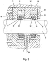
- a sealing element 8, 9, shown in detail in FIG Fig. 3 here in each case comprises an L-shaped rigid support ring 36 which rests on the radial leg of the axially outer chamber discs 21, 23 and radially spaced from the axial leg of the axially outer chamber discs 21, 23 is arranged.
- At the radial leg of the support ring 36 is axially on a hydraulic sealing ring 38 at.
- a resilient Mauab Whyinheit 39 for example, an O-ring can be further arranged.
- This Coab Whyinheit 39 serves to seal the secondary sealing surfaces, here for example between the radial leg of the support ring 36 and the hydraulic sealing ring 38, but also for pressing the hydraulic sealing ring 38 to the sealing surface of the piston rod 3.
- the use of an O-ring as Mauabêtinheit 39 is particularly advantageous because an elastic, non-compressible O-ring converts the upcoming sealing medium pressure into a radial contact pressure with which the sealing ring 38 is pressed against the piston rod 3.
- this Mauabêtinheit 39 can also be omitted, in this case would be the hydraulic Sealing ring 38 also abut the axial leg of the support ring 36 and seal this secondary sealing surface.
- the L-shaped support ring 36, optionally the Mauabêtinheit 39 and the hydraulic sealing ring 38 are axially spaced from the central radial leg of the chamber disc 22 so that the sealing medium, the sealing element 8, 9 for sealing axially against the respective radial leg of the chamber disc 21, 23 can press ,
- the sealing element 8, 9, here the arrangement of L-shaped support ring 36, optionally elastic support ring 39 and hydraulic sealing ring 38 while maintaining the sealing effect with the piston rod 3 moves.
- the third sealing element 11 may also be designed as a rigid or segmented packing ring or as a packing ring combination. The high working pressure p d of the working medium thus acts on this third sealing element 11 in the operational use of the sealing arrangement 1.
- This third sealing element 11 essentially serves, on the one hand, to prevent the penetration of dirt into the actual seal formed by the two sealing elements 8, 9 and, on the other hand, in the case of failure of the sealing element 8 by the third sealing element 11, still maintains a certain sealing effect can, whereby at least an unhindered leakage of sealing medium into the cylinder chamber can be prevented.
- a fourth sealing element 14 here again a combination of an L-shaped support ring, optionally Mauabêtinheit and hydraulic sealing ring as described above, respectively.
- this sealing element 14 on the one hand, a division of the effective pressure difference between the pressure p oil of the sealing medium and acting in the crankcase atmospheric pressure p at the sealing elements 9 and 14 is achieved, and on the other hand, this sealing element 14 again forms a certain security, if the sealing element should fail.
- a hydraulic sealing ring but can be used as a sealing element 14 in turn a rigid, cut or segmented packing ring or a packing ring combination of such packing rings.
- a fifth sealing element 15 here a scraper ring 17, which is arranged in a recess 34 of the last L-shaped chamber disc 24, completed.
- the differential pressure wiper ring 17 is arranged in an L-shaped rigid support ring 16 and can also be pressed by springs or other bias axially to the support ring 16 to prevent axial reciprocation of the scraper ring 17 ..
- adhering to the piston rod 3 sealing medium is removed from the Kolbestange 3. This excess sealing medium can be collected in the recess 34 and discharged from there by appropriate discharges and fed to a sealing medium reservoir.
- the fifth sealing element 15 prevents penetration of dirt into the actual seal formed by the two sealing elements 8, 9 and optionally sealing element 14.
- the third, fourth and fifth sealing elements 11, 14, 15 are optional in the sealing arrangement 1 and can be used in any combination depending on requirements and application.
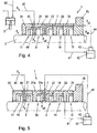
- FIGS. 4 to 6 Further versions are in the FIGS. 4 to 6 shown.
- the cylinder is held in front of the first sealing element 8, the pressure on the suction pressure p s of the compressor.
- This has the advantage that only the (low) static suction pressure p s has to be sealed by the first and second sealing elements 8, 9.
- the (high) dynamic cylinder pressure p d -p s is reduced by a sealing element 11 located in front of it.
- the necessary pressure p oil of the sealing medium can therefore be correspondingly lowered.
- At the individual sealing elements 8, 9 is therefore also a lower pressure difference, whereby the requirements for the sealing elements 8, 9 can be reduced.
- compressor applications typically require 8,000 hours of operation without failure for the seal assembly 1.
- hydraulic sealing rings are unsuitable as sealing elements 8, 9, since they would not reach the required service life under such operating conditions.
- the first and second sealing element 8, 9 formed by two hydraulic sealing rings, such as Fig. 1 described.
- Cylinder side before and axially spaced from the first sealing element 8 is a third sealing element 11, here in the form of a packing ring combination arranged.
- the third sealing element 11 may also be designed as a rigid or segmented packing ring or as a packing ring combination. Since the first sealing element 8 and third sealing element 11 are arranged axially spaced from one another, a gap 49 is formed between these sealing elements 8, 11, which is bounded radially here by the first chamber disk 21.
- the pressure via a supply line 40 in the first chamber disc 21, which is connected via a feed line 45 with the suction pressure p s , for example, with the suction line 60 of the compressor, maintained at suction pressure p s .
- the static suction pressure p s acts in the intermediate space 49 between the first sealing element 8 and third sealing element 11 thus the static suction pressure p s acts.
- the sealing medium thus only needs to be sealed off from the suction pressure p s .
- the dynamic pressure difference p d - p s is degraded by the third sealing element 11, here a packing ring combination, which is substantially less pressure sensitive than a hydraulic sealing ring. With regard to the acting pressures, therefore, only more p oil > p s must be fulfilled.
- a fourth sealing element 14 in the form of a hydraulic sealing ring as above to Fig. 2 described
- a fifth sealing element 15 in the form of a scraper ring also as above to Fig. 2 described, provided. Regarding their function is to the description of Fig. 2 and 3 directed.
- the fourth sealing element 14 can also be omitted.
- the fifth sealing element 15 is, especially when using hydraulic sealing rings with "back suction" as described above, not mandatory. If present, the sealing medium adhering to the piston rod 3 is removed by the fifth sealing element 15 (scraper ring), so that substantially no sealing medium enters the crankcase.
- the retained sealing medium is fed via a sealing medium line 41 to a sealing medium reservoir 42.
- sealing medium is supplied under pressure p oil by means of a pump 43 via a feed line 44 to the feed 7. Any lost in the cylinder chamber sealing medium, especially when using a packing ring or a packing ring combination as the first sealing element 8, must be regularly refilled into the sealing medium reservoir.
- the suction pressure p s suddenly acts on one side of the sixth sealing element 8a, and the sealing medium pressure p oil on the other side, and the sixth sealing element 8a can be designed such that it is activated in this case and through the Pressure of the sealing medium p oil sealing against the piston rod 3 is pressed.
- the sixth sealing element 8a thus serves the safety and maintenance of the sealing effect in case of failure of the first sealing element 8a.
- a sixth sealing element 8a could also be used in a sealing arrangement as in FIG Fig. 2 shown used.
- a scraper ring is provided on the cylinder side, as in Fig. 6 shown.
- a seventh sealing element 50 in the form of a scraper ring is arranged between the first sealing element 8 and the third sealing element 11 in a further seventh chamber disk 51.
- the removed by the scraper ring of the piston rod 3 Dichimedium is discharged via a discharge line 48 from the recess 52 formed by the seventh chamber disc 51.
- the discharge line 48 opens here into a second sealing medium reservoir 46, which is held at suction pressure p s , as in Fig.
- the second sealing medium reservoir 46 may be connected via a throttle 53 and a connecting line 47 with the first sealing medium reservoir 42.
- the throttle 53 is necessary because the first sealing medium reservoir 42, as a rule, for example, is held by a vent to atmospheric pressure p at, and otherwise the sealing medium would freely flow into the first sealing medium reservoir 42nd.
- a scraper ring could also in a sealing arrangement 1 after the Fig. 2 be used. In this case, the scraper ring could be held without differential pressure, by the force acting in front of the scraper ring pressure through corresponding connecting holes in the scraper ring receiving recess is guided.
Landscapes
- Engineering & Computer Science (AREA)
- General Engineering & Computer Science (AREA)
- Mechanical Engineering (AREA)
- Sealing Devices (AREA)
- Compressor (AREA)
Description
- Die gegenständliche Erfindung betrifft eine Dichtanordnung zur Abdichtung einer hin- und hergehenden Kolbenstange eines Kolbenkompressors mit einem ersten und zweiten Dichtelement, die in einer Ausnehmung der Dichtanordnung axial beabstandet angeordnet sind, wobei die Dichtelemente jeweils an einem axialen Ende der Ausnehmung und an der Kolbenstange anliegend angeordnet sind und in der Dichtanordnung eine Zuleitung für ein Dichtmedium vorgesehen ist, die mit der Ausnehmung verbunden ist.
- Herkömmliche Abdichtungen zwischen einer hin- und herbewegten Kolbenstange, z.B. eines Kolbenkompressors, und eines feststehenden Maschinenteils zur Abdichtung eines Raumes mit hohen Druck, z.B. der Arbeitsdruck im Zylinder des Kompressors, gegenüber einen Raum mit niedrigem Druck, z.B. der Atmosphärendruck im Kurbelgehäuse des Kompressors, werden in der Regel als Dichtpackungen ausgeführt. Eine solche Dichtpackung umfasst mehrere axial hintereinander angeordnete Packungsringe bzw. Packungsring-Kombinationen. Am häufigsten werden Kombinationen aus einem radial geschnittenen und einem tangential geschnittenen Packungsring verwendet, wie z.B. aus der
EP 1 146 264 A2 hervorgehend. Daneben werden auch segmentierte Ringdesigns, bei denen ein Packungsring aus mehreren Ringsegmenten zusammengesetzt wird, eingesetzt, wie z.B. aus derUS 4 350 349 A bekannt. Solche Abdichtungen sind jedoch keine zu 100% dichten Systeme, sondern weisen immer eine gewisse Leckagemenge auf, die durch die Abdichtung entweicht. - In gewissen Anwendungen von Kompressoren, wie z.B. in Kompressorstationen bei der Beförderung von Erdgas, wird es aus Umweltschutzgründen immer wichtiger (auch durch immer strenger werdende Vorgabe des Gesetzgebers), die Leckage des Arbeitsmediums (z.B. Erdgas) zu minimieren. Es müssten daher durch herkömmliche Dichtpackungen hohe Anforderungen erfüllt werden, was allerdings nicht immer möglich ist, aber zumindest den Aufwand für die Abdichtung erheblich erhöhen würde.
- Es sind aus dem Stand der Technik auch Abdichtungen zwischen zwei relativ zueinander bewegten Bauteilen, wie z.B. zwischen einer Kolbenstange und einem Maschinengehäuse, bekannt, die nach dem Prinzip einer "Flüssigkeitssperre" arbeiten. Dabei wird zwischen zwei Dichtelementen ein Dichtmedium (z.B. Öl oder eine andere geeignete Flüssigkeit) unter einem höheren Druck als der Umgebungsdruck, z.B. der Arbeitsdruck im Zylinder eines Kompressors, zugeführt. Damit kann ein Arbeitsmedium, wie z.B. ein Gas oder Luft, das ein niedrigeres Druckniveau aufweist als der Druck des Dichtmediums, durch die Abdichtung nicht nach außen dringen. Ein Beispiel einer solchen Abdichtung ist z.B. in der
DE 28 39 243 A1 mit Öl als Dichtmedium oder in derDE 10 2005 034 908 A1 mit einer ionischen Flüssigkeit als Dichtmedium gezeigt. AuchEP 0 209 999 zeigt eine solche Abdichtung. Solche Abdichtungen werden daher auch als gasdichte Abdichtungen bezeichnet und können auch im Stillstand dicht gehalten werden, solange der Dichtmediumdruck aufrecht erhalten wird. Allerdings kommt es dabei in der Regel zu einer Leckage von Dichtmedium, die entsprechend aufgefangen werden muss. - Insbesondere bei Kolbenkompressoren können neben den Hubbewegungen in axialer Richtung der Kolbenstange aber noch signifikante Bewegungen quer dazu auftreten. Eine Abdichtung einer Kolbenstange eines Kolbenkompressors muss daher in der Lage sein, auch bei solchen Querbewegungen zu funktionieren und sicher abzudichten.
- Es ist daher eine Aufgabe der gegenständlichen Erfindung eine nach dem Prinzip einer Dichtmediumbarriere funktionierende gasdichte Abdichtung einer Kolbenstange anzugeben, die in der Lage ist, mögliche Querbewegungen der Kolbenstange bei Aufrechterhaltung der Dichtwirkung auszugleichen und die eine hohe Betriebssicherheit aufweist.
- Diese Aufgabe wird erfindungsgemäß dadurch gelöst, dass die Dichtelemente in radialer Richtung beabstandet vom radialen Ende der Ausnehmung angeordnet sind, sodass das Dichtmedium axial und an der radial äußeren Umfangsfläche des ersten und zweiten Dichtelements angreift. Durch die radiale Beabstandung zum radialen Ende der Ausnehmung wird sichergestellt, dass die Dichtelemente bei einer allfälligen Querbewegung der Kolbenstange sich mit dieser ungehindert (abgesehen von allfälligen Reibungskräften) mitbewegen können, ohne dass die Dichtwirkung dabei verloren gehen würde. An einem ersten axialen Ende der Dichtanordnung ist in einer dritten Ausnehmung der Dichtanordnung ein drittes Dichtelement angeordnet, das als Packungsring oder Packungsring-Kombination ausgeführt ist. Dieses dritte Dichtelement verhindert einerseits das Eindringen von Schmutz in die Abdichtung, und hält andererseits im Falle des Versagens des benachbarten Dichtelements noch eine gewisse Dichtwirkung aufrecht, womit zumindest ein unerwünschtes ungehindertes Austreten von Dichtmedium verhindert werden kann. Dies erhöht die Betriebssicherheit der Dichtanordnung. Am ersten axialen Ende der Dichtanordnung ist zwischen erstem Dichtelement und drittem Dichtelement in einer weiteren als siebenten bezeichneten Ausnehmung der Dichtanordnung ein Abstreifring angeordnet, um eventuell an der Kolbenstange haftendes Dichtmedium abzustreifen und dem Dichtmediumkreislauf rückzuführen. Die Dichtanordnung ist derart ausgeführt, dass dieser Abstreifring differenzdrucklos gehalten wird, wobei der Druck in der siebenten Ausnehmung (52) im betriebsgemäßen Einsatz mit dem vor dem Abstreifring (50) wirkenden Druck verbunden ist, sodass der Abstreifring (50) differenzdrucklos gehalten wird.
- In einer vorteilhaften und konstruktiv einfachen Ausgestaltung werden die Ausnehmungen in der Dichtanordnung durch zwei L-förmige Kammerscheiben gebildet, die axial aneinanderliegend angeordnet sind, wobei jeweils ein Dichtelement in der durch die L-förmige Kammerscheibe gebildete Ausnehmung angeordnet ist. Solche L-förmigen Kammerscheiben können, z.B. durch durchgehende Bolzen, sehr einfach zu einer kompakten Dichtanordnung zusammengestellt werden. Weiters ist es konstruktiv vorteilhaft, wenn die zwei L-förmigen Kammerscheiben gleichgerichtet angeordnet sind, sodass der radiale Schenkel einer L-förmigen Kammerscheibe zwischen den beiden Dichtelementen angeordnet ist und die beiden Dichtelemente axial beabstandet von diesem radialen Schenkel angeordnet sind. Bei einer solchen Ausführung kann die Zuleitung einfach in diesem mittigen radialen Schenkel angeordnet werden.
- Als Dichtelemente kommen starre, segmentierte oder geschnittene Packungsring oder Packungsring-Kombinationen, oder auch hydraulische Dichtringe in Frage. Damit kann eine hohe Flexibilität erzielt werden und die Dichtanordnung kann optimal auf den jeweiligen konkreten Anwendungsfall und die herrschenden Bedingungen angepasst werden.
- Bei Verwendung eines hydraulischen Dichtringes wird dieser vorteilhaft in einem starren L-förmigen Stützring axial anliegend angeordnet, wobei der Stützring radial beabstandet vom radialen Ende der Ausnehmung bleibt. Dabei kann zwischen Stützring und hydraulischem Dichtring auch eine Nebenabdichteinheit angeordnet ist. Eine solche Anordnung ist kompakt und dichtet sowohl die Hauptdichtfläche (hier zur Kolbenstange), als auch Nebendichtflächen sicher ab.
- Ganz besonders vorteilhaft ist es, wenn in einen zwischen ersten Dichtelement und dritten Dichtelement gebildeten Zwischenraum eine Zuleitung mündet, die im betriebsgemäßen Einsatz mit dem Saugdruck des Kolbenkompressors verbunden ist, sodass in diesem Zwischenraum der Saugdruck wirkt. Dadurch wird erreicht, dass dieser Zwischenraum auf Saugdruck gehalten wird, womit das erste Dichtelement nur mehr gegen den (niedrigen) konstanten Saugdruck abdichten muss. Der (hohe) dynamische Arbeitsdruck wird dabei durch das dritte Dichtelement abgebaut. Dies erleichtert die konstruktive Auslegung der Dichtanordnung und verringert die Anforderungen an das erste Dichtelement, vor allem hinsichtlich geforderter Lebensdauer, erheblich. Außerdem wird dadurch natürlich vorteilhaft erreicht, dass der Betriebsdruck des Dichtmediums erheblich reduziert werden kann und folglich in allen beteiligten Systemen mit niedrigeren Drücken gearbeitet werden kann.
- Die am zweiten Dichtelement wirkende Druckdifferenz kann gesenkt werden, wenn an einem zweiten axialen Ende der Dichtanordnung in einer weiteren vierten Ausnehmung der Dichtanordnung benachbart zum zweiten Dichtelement ein viertes Dichtelement angeordnet ist, das als Packungsring oder Packungsring-Kombination oder als hydraulischer Dichtring ausgeführt ist, da dann die Druckdifferenz auf das zweite und vierte Dichtelement aufgeteilt wird. Diese Maßnahme reduziert die Anforderungen an das zweite Dichtelement, vor allem hinsichtlich geforderter Lebensdauer. Außerdem wird dadurch die Betriebssicherheit der Dichtanordnung erhöht, da das vierte Dichtelement noch eine gewisse Dichtwirkung aufrecht erhält, falls das zweite Dichtelement versagen sollte.
- Um eine Dichtmediumleckage zu verhindern, kann an einem zweiten axialen Ende der Dichtanordnung ein fünftes Dichtelement angeordnet sein, das als Abstreifring ausgeführt ist. Damit wird noch auf der Kolbenstange haftendes Dichtmedium abgestreift, das dem Dichtmediumkreislauf rückgeführt werden kann.
- Die Betriebssicherheit kann auch erhöht werden, indem zwischen erstem Dichtelement und zweitem Dichtelement in einer weiteren sechsten Ausnehmung der Dichtanordnung ein weiteres sechstes Dichtelement angeordnet ist, das als Packungsring oder Packungsring-Kombination oder als hydraulischer Dichtring ausgeführt ist, und das im betriebsgemäßen Einsatz radial beabstandet von der Kolbenstange angeordnet ist. Ein solches Dichtelement ist im normalen Betrieb wirkungslos, wird aber aktiviert, falls das erste Dichtelement ausfallen sollte, da dann am sechsten Dichtelement der abzudichtende Druck ansteht.
- Das als Abstreifring wirkende siebente Dichtelement kann einfach differenzdrucklos gehalten werden, wenn der vor dem Abstreifring wirkende Druck mit der siebenten Ausnehmung verbunden wird.
- Die gegenständliche Erfindung wird nachfolgend anhand der schematischen, beispielhaften, nicht einschränkenden und vorteilhafte Ausgestaltungen zeigenden
Figuren 1 bis 6 beschrieben. Dabei zeigt -
Fig. 1 eine gasdichte Abdichtung und die -
Fig. 2 bis 6 weitere vorteilhafte Ausgestaltungen einer gasdichten Abdichtung. - In
Fig. 1 ist eine Dichtanordnung 1 zur Abdichtung einer axial hin- und hergehenden Kolbenstange 3 eines Kolbenkompressors gegenüber einen abzudichtenden Druck pd eines Arbeitsmediums, z.B. der Zylinderdruck, dargestellt. Die Dichtanordnung 1 ist in einem feststehenden Gehäuseteil 2 des Kompressors angeordnet und dichtet zwischen diesem Gehäuseteil 2 und der bewegten Kolbenstange 3. - Die Dichtanordnung 1 umfasst im gezeigten Beispiel zwei L-förmige Kammerscheiben 4, 5, die im dargestellten Ausführungsbeispiel axial durch eine Trennscheibe 6 getrennt sind. Die L-förmigen Kammerscheiben 4, 5 und die Trennscheibe 6 sind axial aneinander anliegend angeordnet und radial von der Kolbenstange 3 beabstandet, um ein Anstreifen der Kolbenstange 3 an den Kammerscheiben 4, 5 zu verhindern und um eine Beweglichkeit der Kolbenstange 3 quer zur Hubbewegung (angedeutet durch den Doppelpfeil) zu ermöglichen. Im einfachsten Fall kann die Trennscheibe 6 aber auch weggelassen werden. Es sind aber auch andere Ausführungen, z.B. mit T-förmigen Trennscheiben, denkbar. An einer Kammerscheibe 5 kann radial außen auch ein Flansch vorgesehen sein, mittels dem die Dichtanordnung 1 am Gehäuseteil 2 befestigt werden kann. Die Kammerscheiben 4, 5 und gegebenenfalls die Trennscheibe 6 können in bekannter Weise durch einen durchgehenden Bolzen zusammengehalten werden. Durch diese Anordnung entsteht zwischen den L-förmigen Kammerscheiben 4, 5, gegebenenfalls der Trennscheibe 6 und der Kolbenstange 3 eine Ausnehmung 10. In dieser Ausnehmung 10 sind ein erstes und zweites Dichtelement 8, 9 angeordnet, wobei die Dichtelemente 8, 9 durch den wirkenden Druck eines in die Ausnehmung 10 zugeführten Dichtmediums jeweils an den axialen Enden der Ausnehmung 10, also an den radialen Schenkeln der L-förmigen Kammerscheiben 4, 5, anliegen und axial voneinander getrennt angeordnet sind (die Orientierungen "axial" und "radial" sind auf die Orientierung der Kolbenstange 3 bezogen). Das erste und zweite Dichtelement 8, 9 sind radial außen beabstandet von den Kammerscheiben 4, 5, also von den axialen Schenkeln der Kammerscheiben 4, 5, angeordnet und liegen radial innen an der Dichtfläche an der Kolbenstange 3 an. Die Dichtelemente 8, 9 können sich somit mit der Kolbenstange 3 quer zur Hubbewegung frei bewegen (abgesehen von Reibungskräften zwischen Dichtelement 8, 9 und Kammerscheibe 4, 5). In der Dichtanordnung 1 ist weiters eine Zuleitung 7 vorgesehen, die mit der Ausnehmung 10 verbunden ist und über die ein Dichtmedium, wie z.B. ein Öl, unter einem Druck poil, der größer ist als der abzudichtende Druck pd, in die Ausnehmung 10 zugeführt werden kann. Im Falle eines sich dynamisch ändernden Arbeitsdruckes pd muss natürlich gelten poil > pd,max, oder der Druck des Dichtmediums wird dynamisch an den Druck des Arbeitsmediums angepasst, sodass immer gilt poil > pd. Das Dichtmedium ist somit durch die Dichtelemente 8, 9 in der Ausnehmung 10 eingeschlossen und wirkt radial außen und axial auf die Dichtelemente 8, 9, die somit radial nach innen an die Kolbenstange 3 und axial an die Kammerscheiben 4, 5 gedrückt werden und somit abdichten. Dadurch entsteht eine Dichtmediumbarriere, die eine Leckage des abzudichtenden gasförmigen Arbeitsmediums des Kompressors verhindert. Bei einer allfälligen Bewegung der Kolbenstange 3 quer zur Hubbewegung werden die Dichtelemente 8, 9 ohne Beeinträchtigung der Dichtwirkung mitbewegt.
- Als Dichtelemente 8, 9 können entweder bekannte hydraulische Dichtringe, wie z.B. ein Lippendichtring oder ein Kompaktdichtring, mit einer an der Kolbenstange 3 anliegenden Dichtlippe, oder aber auch hinlänglich bekannte starre, geschnittene oder segmentierte Packungsringe oder Packungsring-Kombinationen, wie z.B. eine Kombination aus einem radial und tangential geschnittenen Packungsring, eingesetzt werden. Hydraulische Dichtringe können bekanntermaßen auch so ausgeführt sein, dass Dichtmedium, das bei einem Hub durch die Dichtlippe durchgepresst wird, beim Gegenhub durch die Dichtlippe wieder "zurückgesaugt" wird, sodass in Summe keine Leckage von Dichtmedium durch den hydraulischen Dichtring entsteht. Bei der Verwendung von Packungsringen oder Packungsring-Kombinationen entsteht gewöhnlich eine geringe Leckage von Dichtmedium durch die Abdichtung, die aber in der Regel kein Problem darstellt. Weiters entsteht bei Packungsringen in der Regel auch eine Stillstandsleckage, während ein hydraulischer Dichtring durch den Dichtmediumdruck auch im Stillstand dichtet, zumindest solange der Dichtmediumdruck aufrecht erhalten wird.
- In
Fig. 2 ist eine weitere vorteilhafte Ausgestaltung der Dichtanordnung 1 dargestellt. Die Dichtanordnung 1 umfasst hier mehrere hintereinander angeordnete L-förmige Kammerscheiben 20, 21, 22, 23, 24, wobei die L-förmigen Kammerscheiben 20, 21, 22, 23, 24 hier allesamt gleichgerichtet ausgerichtet sind, womit die axialen Schenkel alle in dieselbe Richtung weisen. Es sind aber auch andere Ausführungen, z.B. mit T-förmigen Trennscheiben, denkbar. Am kurbelgehäuseseitigen Ende K wird diese Dichtanordnung 1 in axialer Richtung durch eine Endscheibe 25, die als Flansch zur Befestigung im Gehäuseteil 2 ausgeformt ist, abgeschlossen. Die Kammerscheiben 20, 21, 22, 23, 24 und die Endscheibe 25 sind wiederum radial beabstandet von der Kolbenstange 3 angeordnet. Zwischen einer L-förmigen Kammerscheibe 20, 21, 22, 23, 24 und dem radialen Schenkel der benachbarten Kammerscheibe 20, 21, 22, 23, 24 bzw. der Endscheibe 25 bilden sich somit Ausnehmungen 30, 31, 32, 33, 34 aus, in denen nun Dichtelemente mit unterschiedlichen Funktionen und axial voneinander beabstandet angeordnet sein können. Die einzelnen Dichtelemente sind aber allesamt radial beabstandet von den jeweiligen radialen Enden der Ausnehmungen 30, 31, 32, 33, 34 angeordnet, damit die Kolbenstange 3 ungehindert quer zur Hubbewegung bewegbar bleibt. - Die eigentliche Abdichtung erfolgt durch die Dichtelemente 8, 9, die in den von drei benachbarten Kammerscheiben 21, 22, 23 gebildeten Ausnehmungen 31, 32 angeordnet sind, wie oben zu
Fig. 1 beschrieben. Die Zuleitung 7 für das Dichtmedium kann dazu durch den radialen Schenkel einer L-förmigen Kammerscheibe 22 geführt werden. Ein Dichtelement 8, 9, im Detail dargestellt inFig. 3 , umfasst hier jeweils einen L-förmigen starren Stützring 36, der am radialen Schenkel der axial äußeren Kammerscheiben 21, 23 anliegt und radial beabstandet vom axialen Schenkel der axial äußeren Kammerscheiben 21, 23 angeordnet ist. Am radialen Schenkel des Stützringes 36 liegt axial ein hydraulischer Dichtring 38 an. Zwischen dem axialen Schenkel des Stützringes 36 und dem hydraulischen Dichtring 38 kann weiters eine elastische Nebenabdichteinheit 39, z.B. ein O-Ring, angeordnet sein. Diese Nebenabdichteinheit 39 dient zum Abdichten der Nebendichtflächen, hier z.B. zwischen radialem Schenkel des Stützringes 36 und dem hydraulischen Dichtring 38, aber auch zum Andrücken des hydraulischen Dichtringes 38 an die Dichtfläche der Kolbenstange 3. Die Verwendung eines O-Ringes als Nebenabdichteinheit 39 ist besonders vorteilhaft, da ein elastischer, nicht kompressibler O-Ring den anstehenden Dichtmediumdruck in eine radiale Anpresskraft, mit der der Dichtring 38 gegen die Kolbenstange 3 gepresst wird, umwandelt. Diese Nebenabdichteinheit 39 kann aber auch entfallen, in diesem Fall würde der hydraulische Dichtring 38 auch am axialen Schenkel des Stützringes 36 anliegen und diese Nebendichtfläche dichten. Der L-förmige Stützring 36, gegebenenfalls die Nebenabdichteinheit 39 und der hydraulische Dichtring 38 sind axial vom mittigen radialen Schenkel der Kammerscheibe 22 beabstandet, damit das Dichtmedium das Dichtelement 8, 9 zur Abdichtung axial an den jeweiligen radialen Schenkel der Kammerscheibe 21, 23 andrücken kann. Bei einer radialen Bewegung der Kolbenstange 3 wird das Dichtelement 8, 9, hier die Anordnung aus L-förmigen Stützring 36, gegebenenfalls elastischen Stützring 39 und hydraulischen Dichtring 38, unter Beibehaltung der Dichtwirkung mit der Kolbenstange 3 mitbewegt. - Am zylinderseitigen Ende Z der Dichtanordnung 1 ist vor den Dichtelementen 8, 9 und axial beabstandet dazu in der Ausnehmung 30 der L-förmigen Kammerscheibe 20 ein drittes Dichtelement 11, hier eine Kombination aus einem radial geschnittenen 12 und tangential geschnittenen Packungsring 13, angeordnet. Das dritte Dichtelement 11 kann aber auch als starrer oder segmentierter Packungsring oder als eine Packungsring-Kombination ausgeführt sein. An diesem dritten Dichtelement 11 wirkt somit im betriebsgemäßen Einsatz der Dichtanordnung 1 der hohe Arbeitsdruck pd des Arbeitsmediums. Dieses dritte Dichtelement 11 dient im Wesentlichen dazu, einerseits das Eindringen von Schmutz in die eigentliche Abdichtung gebildet durch die beiden Dichtelemente 8, 9 zu verhindern, und andererseits im Falle des Versagens des Dichtelements 8 durch das dritte Dichtelement 11 noch eine gewisse Dichtwirkung aufrecht erhalten zu können, womit zumindest ein ungehindertes Austreten von Dichtmedium in den Zylinderraum verhindert werden kann.
- Am kurbelgehäuseseitigen Ende K ist nach den Dichtelementen 8, 9 in der Ausnehmung 33 der L-förmigen Kammerscheibe 23 ein viertes Dichtelement 14, hier wieder eine Kombination aus einem L-förmigen Stützring, gegebenenfalls Nebenabdichteinheit und hydraulischem Dichtring wie oben beschrieben, angeordnet. Durch dieses vierte Dichtelement 14 wird einerseits eine Aufteilung der wirkenden Druckdifferenz zwischen dem Druck poil des Dichtmediums und des im Kurbelgehäuse wirkenden Atmosphärendruckes pat auf die Dichtelemente 9 und 14 erreicht, und andererseits bildet dieses Dichtelement 14 wiederum eine gewisse Sicherheit, falls das Dichtelement 9 versagen sollte. Anstelle eines hydraulischen Dichtringes kann aber als Dichtelement 14 wiederum ein starrer, geschnittenen oder segmentierter Packungsring bzw. eine Packungsring-Kombination aus solchen Packungsringen verwendet werden.
- Weiters kann die Dichtanordnung 1 am kurbelgehäuseseitigen Ende K durch ein fünftes Dichtelement 15, hier ein Abstreifring 17, der in einer Ausnehmung 34 der letzten L-förmigen Kammerscheibe 24 angeordnet ist, abgeschlossen werden. Der differenzdrucklose Abstreifring 17 ist dabei in einem L-förmigen starren Stützring 16 angeordnet und kann auch durch Federn oder eine andere Vorspannung axial an den Stützring 16 angedrückt werden, um ein axiales Hin- und Herbewegen des Abstreifringes 17 zu unterbinden.. Durch den Abstreifring 17 wird überschüssiges, an der Kolbenstange 3 haftendes Dichtmedium von der Kolbestange 3 entfernt. Dieses überschüssige Dichtmedium kann in der Ausnehmung 34 gesammelt werden und von dort durch entsprechende Ableitungen abgeführt und einem Dichtmediumreservoir zugeführt werden. Außerdem verhindert das fünfte Dichtelement 15 ein Eindringen von Schmutz in die eigentliche Abdichtung gebildet durch die beiden Dichtelemente 8, 9 und gegebenenfalls Dichtelement 14.
- Das dritte, vierte und fünfte Dichtelement 11, 14, 15 sind in der Dichtanordnung 1 optional und können je nach Bedarf und Anwendung in beliebigen Kombinationen eingesetzt werden.
- Weitere Ausführungen werden in den
Figuren 4 bis 6 gezeigt. Bei diesen Ausführungen wird zylinderseitig vor dem ersten Dichtelement 8 der Druck auf den Saugdruck ps des Kompressors gehalten. Dies hat den Vorteil, dass durch das erste und zweite Dichtelement 8, 9 nur mehr der (niedrige) statische Saugdruck ps abgedichtet werden muss. Der (hohe) dynamische Zylinderdruck pd - ps wird durch ein davor liegendes Dichtelement 11 abgebaut. Der notwendige Druck poil des Dichtmediums kann daher entsprechend weit abgesenkt werden. An den einzelnen Dichtelementen 8, 9 liegt daher ebenfalls eine niedrigere Druckdifferenz an, wodurch die Anforderungen an die Dichtelemente 8, 9 verringert werden können. Z.B. werden für Kompressoranwendungen typischerweise 8.000 Betriebsstunden ohne Ausfall für die Dichtanordnung 1 gefordert. Aufgrund der hohen Relativgeschwindigkeiten zwischen Dichtelementen 8, 9 und Kolbenstange 3 und den möglichen hohen abzudichtenden Druckdifferenzen sind daher z.B. bei gewissen Anwendungen hydraulische Dichtringe als Dichtelemente 8, 9 ungeeignet, da diese bei solchen Betriebsbedingungen die geforderte Lebensdauer nicht erreichen würden. Durch die Absenkung der abzudichtenden Druckdifferenz durch die oben beschriebene Maßnahme sinken jedoch diese Anforderungen an die Dichtelemente 8, 9, wodurch auch hydraulische Dichtringe eingesetzt werden können. - In einer möglichen Ausgestaltung der Dichtanordnung 1 werden, wie in
Fig. 4 gezeigt, das erste und zweite Dichtelement 8, 9 durch zwei hydraulische Dichtringe gebildet, wie zuFig. 1 beschrieben. Zylinderseitig vor dem und axial beabstandet zum ersten Dichtelement 8 ist ein drittes Dichtelement 11, hier in Form einer Packungsring-Kombination, angeordnet. Das dritte Dichtelement 11 kann aber auch als starrer oder segmentierter Packungsring oder als eine Packungsring-Kombination ausgeführt sein. Da das erste Dichtelement 8 und dritte Dichtelement 11 axial beabstandet voneinander angeordnet sind, entsteht zwischen diesen Dichtelementen 8, 11 ein Zwischenraum 49, der hier radial durch die erste Kammerscheibe 21 begrenzt wird. In diesen Zwischenraum 49 wird der Druck über eine Zuleitung 40 in der ersten Kammerscheibe 21, die über eine Zuführleitung 45 mit dem Saugdruck ps, z.B. mit der Saugleitung 60 des Kompressors, verbunden ist, auf Saugdruck ps gehalten. Im Zwischenraum 49 zwischen ersten Dichtelement 8 und dritten Dichtelement 11 wirkt somit der statische Saugdruck ps. Durch das Dichtmedium muss somit nur mehr gegenüber dem Saugdruck ps abgedichtet werden. Die dynamische Druckdifferenz pd - ps wird durch das dritte Dichtelement 11, hier eine Packungsring-Kombination, abgebaut, die wesentlich druckunempfindlicher ist als ein hydraulischer Dichtring. Hinsichtlich der wirkenden Drücke muss daher nur mehr poil>ps erfüllt werden. - Zur Kurbelgehäuseseite K sind wiederum ein viertes Dichtelement 14 in Form eines hydraulischen Dichtringes, wie oben zu
Fig. 2 beschrieben, und ein fünftes Dichtelement 15 in Form eines Abstreifringes, ebenfalls wie oben zuFig. 2 beschrieben, vorgesehen. Hinsichtlich deren Funktion wird auf die Beschreibung zurFig. 2 und3 verwiesen. Auf das vierte Dichtelement 14 kann auch verzichtet werden. Auch das fünfte Dichtelement 15 ist, insbesondere bei der Verwendung von hydraulischen Dichtringen mit "Rücksaugung" wie oben beschrieben, nicht zwingend erforderlich. Falls vorhanden wird durch das fünfte Dichtelement 15 (Abstreifring) das auf der Kolbenstange 3 haftende Dichtmedium entfernt, womit im Wesentlichen kein Dichtmedium in das Kurbelgehäuse gelangt. Das zurückgehaltene Dichtmedium wird über eine Dichtmediumleitung 41 einem Dichtmediumreservoir 42 zugeführt. Von dort wird Dichtmedium unter einen Druck poil mittels einer Pumpe 43 über eine Zuführleitung 44 der Zuführung 7 zugeführt. Eventuell in den Zylinderraum verlorengegangenes Dichtmedium, insbesondere bei Verwendung eines Packungsringes oder einer Packungsring-Kombination als erstes Dichtelement 8, muss regelmäßig in das Dichtmediumreservoir nachgefüllt werden. - Im Ausführungsbeispiel nach der
Fig. 5 werden anstatt hydraulischer Dichtringe, Packungsring-Kombinationen als erstes und zweites Dichtelement 8, 9 verwendet. Damit ergibt sich immer eine gewisse Dichtmediumleckage in den Zylinderraum und in das Kurbelgehäuse, da eine solche Packungsring-Kombination nie gänzlich dicht ist. Ansonsten ist zwischen ersten und zweiten Dichtelement 8, 9, in der Ausnehmung 31 a einer weiteren sechsten Kammerscheibe 21 a ein weiteres sechstes Dichtelement 8a, hier z.B. ein hydraulischer Dichtring (könnte aber ebenso ein Packungsring oder eine Packungsring-Kombination sein), vorgesehen. Dieses sechste Dichtelement 8a ist aber mit Übermaß eingebaut, d.h. es liegt vorerst radial innen nicht dichtend an der Kolbenstange 3 an, und ist daher vorerst nicht aktiviert. Versagt jedoch das erste Dichtelement 8, so wirkt an einer Seite des sechsten Dichtelements 8a plötzlich der Saugdruck ps und an der anderen Seite der Dichtmediumdruck poil und das sechste Dichtelement 8a kann so ausgelegt sein, dass es in diesem Fall aktiviert wird und durch den Druck des Dichtmediums poil dichtend gegen die Kolbenstange 3 gepresst wird. Das sechste Dichtelement 8a dient somit der Sicherheit und Aufrechterhaltung der Dichtwirkung bei Ausfall des ersten Dichtelements 8a. Ein solches sechstes Dichtelement 8a könnte aber natürlich auch in einer Dichtanordnung wie inFig. 2 gezeigt eingesetzt werden. - Bei den Ausführungen nach der
Fig. 4 und 5 kann es zu einer Dichtmediumleckage in den Zylinderraum kommen. Um auch eine solche Leckage zu verhindern, wird erfindungsgemäß zylinderseitig ein Abstreifring vorgesehen, wie inFig. 6 gezeigt. Dazu ist zwischen erstem Dichtelement 8 und drittem Dichtelement 11 in einer weiteren siebenten Kammerscheibe 51 ein siebentes Dichtelement 50 in Form eines Abstreifringes angeordnet. Das durch den Abstreifring von der Kolbenstange 3 entfernte Dichimedium wird über eine Abführleitung 48 aus der durch die siebente Kammerscheibe 51 gebildete Ausnehmung 52 abgeführt. Die Abführleitung 48 mündet hier in ein zweites Dichtmediumreservoir 46, das auf Saugdruck ps gehalten wird, wie inFig. 6 angedeutet, um den Zwischenraum 49 auf Saugdruck ps zu halten und um den Abstreifring damit differenzdrucklos zu halten. Gleiches kann auch erreicht werden, indem der Saugdruck ps in die Ausnehmung 62 der siebenten Kammerscheibe 51 geführt wird, z.B. durch eine Verbindungsbohrung 54, die die Zuführung 40 mit der Ausnehmung 52 verbindet, wie inFig. 6 strichliert angedeutet Das zweite Dichtmediumreservoir 46 kann über eine Drossel 53 und einer Verbindungsleitung 47 mit dem ersten Dichtmediumreservoir 42 verbunden sein. Die Drossel 53 ist notwendig, da das erste Dichtmediumreservoir 42 in der Regel, z.B. durch eine Entlüftung, auf Atmosphärendruck pat gehalten wird, und ansonsten das Dichtmedium ungehindert in das erste Dichtmediumreservoir 42 strömen würde. Ein solcher Abstreifring könnte aber auch in einer Dichtanordnung 1 nach derFig. 2 eingesetzt werden. In diesem Fall könnte der Abstreifring differenzdrucklos gehalten werden, indem der vor dem Abstreifring wirkende Druck durch entsprechende Verbindungsbohrungen auch in die den Abstreifring aufnehmende Ausnehmung geführt wird. - Die oben beschriebenen Ausgestaltungen einer erfindungsgemäßen Dichtanordnung 1 sind nur beispielhaft und es sind beliebige Kombinationen aus den beschriebenen Dichtelementen 8, 8a, 9, 11, 14, 15 und 50 denkbar. Die erfindungsgemäße Dichtanordnung wird durch die sich anschließenden Ansprüche begrenzt.
Claims (13)
- Dichtanordnung zur Abdichtung einer hin- und hergehenden Kolbenstange (3) eines Kolbenkompressors mit einem ersten (8) und zweiten Dichtelement (9), die in einer Ausnehmung (10, 31, 32) der Dichtanordnung (1) axial beabstandet angeordnet sind, wobei die Dichtelemente (8, 9) jeweils an einem axialen Ende der Ausnehmung (10, 31, 32) und an der Kolbenstange (3) anliegend angeordnet sind und in der Dichtanordnung (1) eine Zuleitung (7) für ein Dichtmedium vorgesehen ist, die mit der Ausnehmung (10, 31, 32) verbunden ist, wobei das erste und zweite Dichtelement (8, 9) in radialer Richtung beabstandet vom radialen Ende der Ausnehmung (10, 31, 32) angeordnet sind, sodass das Dichtmedium axial und an der radial äußeren Umfangsfläche des ersten und zweiten Dichtelements (8, 9) angreift, dadurch gekennzeichnet, dass an einem ersten axialen Ende der Dichtanordnung (1) in einer weiteren dritten Ausnehmung (30) der Dichtanordnung (1) ein drittes Dichtelement (11) angeordnet ist, das als Packungsring oder Packungsring-Kombination ausgeführt ist und zwischen erstem Dichtelement (8) und drittem Dichtelement (11) in einer weiteren als siebenten bezeichneten Ausnehmung (52) der Dichtanordnung (1) ein Abstreifring (50) angeordnet ist, wobei die Dichtanordnung (1) derart ausgeführt ist, dass dieser Abstreifring (50) differenzdrucklos gehalten wird, wobei der Druck in der siebenten Ausnehmung (52) im betriebsgemäßen Einsatz mit dem vor dem Abstreifring (50) wirkenden Druck verbunden ist, sodass der Abstreifring (50) differenzdrucklos gehalten wird.
- Dichtanordnung nach Anspruch 1, dadurch gekennzeichnet, dass in der Dichtanordnung (1) zwei L-förmige Kammerscheiben (4, 5, 21, 22) axial aneinanderliegend angeordnet sind und jeweils ein Dichtelement (8, 9) in der durch die L-förmige Kammerscheibe (4, 5, 21, 22) gebildeten Ausnehmung (10, 31, 32) angeordnet ist.
- Dichtanordnung nach Anspruch 2, dadurch gekennzeichnet, dass die zwei L-förmigen Kammerscheiben (21, 22) gleichgerichtet angeordnet sind, sodass der radiale Schenkel einer L-förmigen Kammerscheibe (22) zwischen den beiden Dichtelementen (8, 9) angeordnet ist und die beiden Dichtelemente (8, 9) axial beabstandet von diesem radialen Schenkel angeordnet sind.
- Dichtanordnung nach Anspruch 3, dadurch gekennzeichnet, dass die Zuleitung (7) in diesem mittigen radialen Schenkel angeordnet ist.
- Dichtanordnung nach einem der Ansprüche 1 bis 4, dadurch gekennzeichnet, dass als zumindest ein Dichtelement (8, 9) ein starrer, segmentierter oder geschnittener Packungsring oder eine Packungsring-Kombination daraus vorgesehen ist.
- Dichtanordnung nach einem der Ansprüche 1 bis 4, dadurch gekennzeichnet, dass als zumindest ein Dichtelement (8, 9) ein hydraulischer Dichtring (38) vorgesehen ist.
- Dichtanordnung nach Anspruch 6, dadurch gekennzeichnet, dass der hydraulische Dichtring (38) in einem starren L-förmigen Stützring (36) axial anliegend angeordnet ist und der Stützring (36) radial beabstandet vom radialen Ende der Ausnehmung (10, 31, 32) angeordnet ist.
- Dichtanordnung nach Anspruch 7, dadurch gekennzeichnet, dass zwischen Stützring (36) und hydraulischem Dichtring (38) eine Nebenabdichteinheit (39) angeordnet ist.
- Dichtanordnung nach einem der Ansprüche 1 bis 8, dadurch gekennzeichnet, dass in einem zwischen ersten Dichtelement (8) und dritten Dichtelement (11) gebildeten Zwischenraum (49) eine Zuleitung (40) mündet, die im betriebsgemäßen Einsatz mit dem Saugdruck (ps) des Kolbenkompressors verbunden ist, sodass in diesem Zwischenraum (49) der Saugdruck (ps) wirkt.
- Dichtanordnung nach einem der Ansprüche 1 bis 9, dadurch gekennzeichnet, dass an einem zweiten axialen Ende der Dichtanordnung (1) in einer weiteren vierten Ausnehmung (33) der Dichtanordnung (1) ein viertes Dichtelement (14) angeordnet ist, das als Packungsring oder Packungsring-Kombination oder als hydraulischer Dichtring ausgeführt ist.
- Dichtanordnung nach einem der Ansprüche 1 bis 10, dadurch gekennzeichnet, dass an einem zweiten axialen Ende der Dichtanordnung (1) in einer weiteren fünften Ausnehmung (34) der Dichtanordnung (1) ein fünftes Dichtelement (15) angeordnet ist, das als Abstreifring (17) ausgeführt ist.
- Dichtanordnung nach Anspruch 10 oder 11, dadurch gekennzeichnet, dass der hydraulische Dichtring und/oder der Abstreifring (17) in einer durch einen L-förmigen Stützring (16) gebildeten Ausnehmung angeordnet ist.
- Dichtanordnung nach einem der Ansprüche 1 bis 12, dadurch gekennzeichnet, dass zwischen erstem Dichtelement (8) und zweitem Dichtelement (9) in einer weiteren sechsten Ausnehmung (31a) der Dichtanordnung (1) ein weiteres sechstes Dichtelement (8a) angeordnet ist, das als Packungsring oder Packungsring-Kombination oder als hydraulischer Dichtring ausgeführt ist, und das im betriebsgemäßen Einsatz radial beabstandet von der Kolbenstange (3) angeordnet ist.
Applications Claiming Priority (2)
| Application Number | Priority Date | Filing Date | Title |
|---|---|---|---|
| AT0003909A AT507564B1 (de) | 2009-01-12 | 2009-01-12 | Dichtanordnung zur abdichtung einer kolbenstange eines kolbenkompressors |
| PCT/EP2010/050216 WO2010079227A1 (de) | 2009-01-12 | 2010-01-11 | Dichtanordnung zur abdichtung einer kolbenstange eines kolbenkompressors |
Publications (3)
| Publication Number | Publication Date |
|---|---|
| EP2376819A1 EP2376819A1 (de) | 2011-10-19 |
| EP2376819B1 EP2376819B1 (de) | 2014-03-26 |
| EP2376819B2 true EP2376819B2 (de) | 2017-10-11 |
Family
ID=42126513
Family Applications (1)
| Application Number | Title | Priority Date | Filing Date |
|---|---|---|---|
| EP10700059.8A Not-in-force EP2376819B2 (de) | 2009-01-12 | 2010-01-11 | Dichtanordnung zur abdichtung einer kolbenstange eines kolbenkompressors |
Country Status (7)
| Country | Link |
|---|---|
| US (1) | US9027934B2 (de) |
| EP (1) | EP2376819B2 (de) |
| JP (1) | JP5538430B2 (de) |
| CN (1) | CN102272492B (de) |
| AT (1) | AT507564B1 (de) |
| BR (1) | BRPI1007292A2 (de) |
| WO (1) | WO2010079227A1 (de) |
Families Citing this family (45)
| Publication number | Priority date | Publication date | Assignee | Title |
|---|---|---|---|---|
| AT507564B1 (de) | 2009-01-12 | 2010-06-15 | Hoerbiger Kompressortech Hold | Dichtanordnung zur abdichtung einer kolbenstange eines kolbenkompressors |
| GB201021266D0 (en) * | 2010-12-14 | 2011-01-26 | Crane John Uk Ltd | Seals |
| AT510171B1 (de) * | 2011-02-17 | 2012-02-15 | Hoerbiger Kompressortech Hold | Dichtpackung für eine hin- und hergehende kolbenstange eines kolbenkompressors |
| NL2006718C2 (en) * | 2011-05-04 | 2012-11-06 | Thomassen Compression Syst Bv | Piston compressor for compressing gas. |
| DE102011119011A1 (de) * | 2011-11-14 | 2013-05-16 | Hydac Technology Gmbh | Gaszylinder, insbesondere Hochdruck-Gaszylinder |
| AT512945B1 (de) * | 2012-06-04 | 2013-12-15 | Hoerbiger Kompressortech Hold | Dichtanordnung zur Abdichtung einer hin- und hergehenden Kolbenstange eines Kolbenkompressors |
| AT513495B1 (de) * | 2012-11-28 | 2014-05-15 | Hoerbiger Kompressortech Hold | Dichtanordnung zur Abdichtung einer hin- und hergehenden Kolbenstange eines Kolbenkompressors |
| CN105247528B (zh) | 2013-06-27 | 2018-05-18 | 英特尔公司 | 连续多因素认证 |
| AT514335B1 (de) * | 2013-07-10 | 2014-12-15 | Hoerbiger Kompressortech Hold | Dichtanordnung zur Abdichtung einer hin- und hergehenden Kolbenstange eines Kolbenkompressors |
| AT513836B1 (de) * | 2013-09-23 | 2014-08-15 | Hoerbiger Kompressortech Hold | Kompressor mit und Verfahren zur Spülung des Kompressorgehäuses mit Spülgas |
| CN203730353U (zh) * | 2014-02-27 | 2014-07-23 | 讯凯国际股份有限公司 | 薄型化轴向气隙式风扇 |
| WO2016087326A1 (en) * | 2014-12-05 | 2016-06-09 | Nuovo Pignone Srl | Packing case for reciprocating machine and method of assembling the same |
| DE102014226429A1 (de) * | 2014-12-18 | 2016-06-23 | Eagleburgmann Germany Gmbh & Co. Kg | Wellendichtungsanordnung einer Fluidmaschine sowie Verfahren zur Abdichtung einer Welle einer Fluidmaschine |
| US20190136858A1 (en) * | 2015-03-30 | 2019-05-09 | Hicor Technologies, Inc. | Compressor with liquid injection cooling |
| CN104879499B (zh) * | 2015-05-04 | 2018-01-23 | 西安近代化学研究所 | 一种防尘密封装置 |
| JP6553969B2 (ja) * | 2015-07-23 | 2019-07-31 | 株式会社日立製作所 | 往復圧縮機 |
| DE102016210731A1 (de) * | 2016-06-16 | 2017-12-21 | Robert Bosch Gmbh | Förderpumpe für kryogene Kraftstoffe |
| JP7227125B2 (ja) * | 2016-08-26 | 2023-02-21 | ブルクハルト コンプレッション アーゲー | オイルワイパパッキンおよびオイルワイパパッキンを取り付ける方法 |
| CN107559186A (zh) * | 2017-09-06 | 2018-01-09 | 芜湖精达机械制造有限公司 | 一种海水泵管路连接装置 |
| FR3072136B1 (fr) * | 2017-10-10 | 2021-11-19 | Atlas Copco Crepelle S A S | Systeme d'etancheisation d'une tige de piston pour une machine a mouvement alternatif et procede pour l'etancheisation d'une telle tige de piston |
| DE102018100637B3 (de) | 2018-01-12 | 2019-06-06 | Dürr Systems Ag | Dichtung und Beschichtungsmittelpumpe mit einer solchen Dichtung |
| JP7176846B2 (ja) * | 2018-03-02 | 2022-11-22 | 極東開発工業株式会社 | コンクリートポンプ |
| CN108799061A (zh) * | 2018-08-15 | 2018-11-13 | 安徽士必达液压器材有限公司 | 一种气体增压泵用超高压活塞 |
| AT521716B1 (de) | 2018-09-20 | 2020-07-15 | Hoerbiger Wien Gmbh | Ölabstreifring für eine Kolbenstange |
| CN109442042B (zh) * | 2018-10-19 | 2023-10-31 | 杭州加一包装技术有限责任公司 | 一种用于粉体环境下的机械部件气体密封结构 |
| CN109323004A (zh) * | 2018-11-21 | 2019-02-12 | 中国航发西安动力控制科技有限公司 | 一种带过渡压力腔的减小间隙泄漏结构 |
| CN109237029B (zh) * | 2018-11-30 | 2022-02-25 | 恒天九五重工有限公司 | 一种旋转密封装置 |
| ES2930042T3 (es) | 2019-01-29 | 2022-12-05 | Hoerbiger Wien Gmbh | Anillo de empaquetadura con abertura de desgaste |
| JP7693547B2 (ja) | 2019-01-29 | 2025-06-17 | ヘルビガー ウィーン ゲゼルシャフト ミット ベシュレンクテル ハフツング | 傾斜したリリーフ開口を備えたパッキンリング |
| CN113474579B (zh) | 2019-01-29 | 2025-01-10 | 贺尔碧格维恩有限公司 | 具有卸荷开口的密封环 |
| US11761538B2 (en) * | 2020-02-06 | 2023-09-19 | Tamar (R.C.) Technologies Development Ltd. | Sealing system for rotary shaft |
| US11788541B2 (en) | 2020-05-18 | 2023-10-17 | Dover Pumps & Process Solutions Segment, Inc. | High pressure gas sealing |
| EP4145025B1 (de) | 2020-09-30 | 2026-05-06 | Sany Automobile Manufacturing Co., Ltd. | Wasserwiderstandsvorrichtung, pumpsystem, pumpmaschine und reinigungsverfahren |
| CN112197003A (zh) * | 2020-10-13 | 2021-01-08 | 自贡东方通用压缩机有限公司 | 一种活塞式压缩机密封机构 |
| DE102020134381A1 (de) * | 2020-12-21 | 2022-06-23 | NEUMAN & ESSER Deutschland GmbH & Co. KG Vertrieb und Anlagentechnik | Kompressor, Scheibenkörper und Dichtung |
| US12313052B2 (en) | 2021-06-08 | 2025-05-27 | Dover Pumps & Process Solutions Segment, Inc. | Expansion chamber for progressive sealing system |
| CN113374682B (zh) * | 2021-07-15 | 2022-05-13 | 西南石油大学 | 一种压裂泵液力端柱塞孔密封结构 |
| CN113915335A (zh) * | 2021-10-14 | 2022-01-11 | 安瑞科(蚌埠)压缩机有限公司 | 一种活塞式压缩机无泄漏密封装置 |
| DE102022202008A1 (de) * | 2022-02-28 | 2023-08-31 | Van Halteren Technologies Boxtel B.V. | Dichtungssystem für einen Verdichter und Verdichter |
| US12435716B2 (en) * | 2022-05-09 | 2025-10-07 | Hoerbiger Wien Gmbh | Pressure packing for a reciprocating piston compressor with buffer gas barrier |
| CN115962281B (zh) * | 2022-07-18 | 2026-03-20 | 江苏汉苏机械股份有限公司 | 活塞杆密封改良结构 |
| CN115789250B (zh) * | 2022-11-09 | 2026-01-16 | 浙江神太太阳能股份有限公司 | 一种快装式罐组合密封盖及热水器内筒 |
| CN116816637A (zh) * | 2023-07-31 | 2023-09-29 | 新疆大全新能源股份有限公司 | 往复式氢气压缩机机封气排放回收利用系统 |
| EP4603726B1 (de) | 2024-02-13 | 2026-07-29 | WinGD Ltd. | Dichtungsanordnung |
| DE102024121403A1 (de) * | 2024-07-26 | 2026-01-29 | Eagleburgmann Germany Gmbh & Co. Kg | Dichtsystem zur Abdichtung zwischen einem rotierenden Bauteil und einem stationären Bauteil |
Family Cites Families (39)
| Publication number | Priority date | Publication date | Assignee | Title |
|---|---|---|---|---|
| US2191265A (en) * | 1936-06-06 | 1940-02-20 | Harley T Wheeler | Segmental metallic packing ring |
| US2714028A (en) * | 1953-07-29 | 1955-07-26 | Morganite Inc | Sealing and packing rings |
| DE1132681B (de) | 1958-10-24 | 1962-07-05 | Linde Eismasch Ag | Stopfbuechsenanordnung fuer die Kolbenstange von Trockenlaufverdichter |
| DE1144873B (de) | 1960-09-07 | 1963-03-07 | Linde Eismasch Ag | Stopfbuechsenanordnung fuer die Kolbenstange von Trockenlaufverdichtern |
| US3194568A (en) * | 1961-06-16 | 1965-07-13 | Dresser Ind | Stuffing box with cooling and vent means |
| US3271037A (en) * | 1963-04-01 | 1966-09-06 | Garlock Inc | Pressure-balanced segmental packing rings |
| US3216651A (en) * | 1963-07-01 | 1965-11-09 | Battelle Development Corp | Seal |
| US3542374A (en) * | 1968-04-24 | 1970-11-24 | Worthington Corp | Packing for piston rods in high pressure nonlube reciprocating compressors |
| US3544118A (en) * | 1968-10-01 | 1970-12-01 | Koppers Co Inc | Pressure balanced shaft seal |
| US3860270A (en) * | 1971-09-30 | 1975-01-14 | Hydrotech Int Inc | Apparatus for effecting a connection to a tubular member or the like |
| US4093239A (en) * | 1976-01-21 | 1978-06-06 | Nippon Piston Ring Co., Ltd. | Piston rod sealing arrangement for a stirling engine |
| JPS5442548A (en) | 1977-09-10 | 1979-04-04 | Kenji Asano | Leak seal liquid return apparatus for stirling engine |
| JPS54140165U (de) * | 1978-03-23 | 1979-09-28 | ||
| US4350349A (en) | 1981-02-12 | 1982-09-21 | Harry A. Robertson, Jr. | Rod packing |
| US4453176A (en) | 1981-12-31 | 1984-06-05 | International Business Machines Corporation | LSI Chip carrier with buried repairable capacitor with low inductance leads |
| JPS58119664U (ja) * | 1982-02-10 | 1983-08-15 | 三井造船株式会社 | 密封装置 |
| US4514148A (en) | 1982-11-01 | 1985-04-30 | Carter Controls, Inc. | Hydraulically actuated pump |
| US4469017A (en) * | 1983-02-23 | 1984-09-04 | Dover Corporation | Static leak seal assembly for use in fluid containing machinery |
| NL8303794A (nl) | 1983-11-03 | 1985-06-03 | Stork Serv Bv | Inrichting voor het behandelen van een wand, zoals een scheepswand. |
| JPS60114373U (ja) * | 1984-01-12 | 1985-08-02 | エヌオーケー株式会社 | 密封装置 |
| JPS60172058A (ja) | 1984-02-17 | 1985-09-05 | Ricoh Co Ltd | 現像装置 |
| DE3577595D1 (de) | 1984-04-25 | 1990-06-13 | Tanken Seiko Kk | Dichtungsvorrichtung fuer pulver. |
| JPS60172058U (ja) * | 1984-04-25 | 1985-11-14 | 炭研精工株式会社 | セグメントシ−ル構造 |
| GB2185542B (en) * | 1985-07-13 | 1988-05-25 | Crane Packing Ltd | Gas tight seal |
| JPS6375668A (ja) | 1986-09-19 | 1988-04-06 | Hitachi Ltd | フロ−インジエクシヨン分析装置 |
| JPS6375668U (de) * | 1986-11-06 | 1988-05-20 | ||
| US5209495A (en) * | 1990-09-04 | 1993-05-11 | Palmour Harold H | Reciprocating rod pump seal assembly |
| DE4205862C1 (de) * | 1992-02-26 | 1993-06-17 | Fa. Carl Freudenberg, 6940 Weinheim, De | |
| DE4211192A1 (de) * | 1992-04-03 | 1993-10-07 | Schreiter Eberhard | Einrichtung zur Überleitung von Druckmedien von einem feststehenden Gehäuse auf eine rotierende Welle |
| JPH0618664A (ja) | 1992-07-06 | 1994-01-28 | Matsushita Electric Ind Co Ltd | 車両用側方監視装置 |
| US5607165A (en) * | 1995-06-07 | 1997-03-04 | Cooper Cameron Corporation | Sealing system for a valve having biassed sealant under pressure |
| JP3687241B2 (ja) * | 1996-12-13 | 2005-08-24 | 株式会社日立製作所 | 封水装置およびその封水装置を備えた水車 |
| US6286837B1 (en) * | 1999-08-24 | 2001-09-11 | Delaware Capital Formation, Inc. | Compressor piston rod packing ring set |
| AT411384B (de) | 2000-04-10 | 2003-12-29 | Hoerbiger Ventilwerke Gmbh | Dichtring-kombination |
| JP2001066757A (ja) * | 2000-08-07 | 2001-03-16 | Seiko Epson Corp | 露光方法 |
| US6932351B1 (en) * | 2003-02-07 | 2005-08-23 | William L. Mowll | Packing case for cooling compressors and other machinery |
| US7118114B2 (en) | 2003-05-15 | 2006-10-10 | Woodward Governor Company | Dynamic sealing arrangement for movable shaft |
| DE102005034908A1 (de) | 2005-07-26 | 2007-02-01 | Linde Ag | Hermetisches Dichtungssystem |
| AT507564B1 (de) | 2009-01-12 | 2010-06-15 | Hoerbiger Kompressortech Hold | Dichtanordnung zur abdichtung einer kolbenstange eines kolbenkompressors |
-
2009
- 2009-01-12 AT AT0003909A patent/AT507564B1/de not_active IP Right Cessation
-
2010
- 2010-01-11 BR BRPI1007292A patent/BRPI1007292A2/pt active Search and Examination
- 2010-01-11 JP JP2011544881A patent/JP5538430B2/ja not_active Expired - Fee Related
- 2010-01-11 CN CN201080004289.4A patent/CN102272492B/zh not_active Expired - Fee Related
- 2010-01-11 EP EP10700059.8A patent/EP2376819B2/de not_active Not-in-force
- 2010-01-11 WO PCT/EP2010/050216 patent/WO2010079227A1/de not_active Ceased
- 2010-01-11 US US13/138,140 patent/US9027934B2/en not_active Expired - Fee Related
Also Published As
| Publication number | Publication date |
|---|---|
| BRPI1007292A2 (pt) | 2016-10-25 |
| JP5538430B2 (ja) | 2014-07-02 |
| AT507564B1 (de) | 2010-06-15 |
| EP2376819B1 (de) | 2014-03-26 |
| AT507564A4 (de) | 2010-06-15 |
| US9027934B2 (en) | 2015-05-12 |
| JP2012515298A (ja) | 2012-07-05 |
| CN102272492A (zh) | 2011-12-07 |
| EP2376819A1 (de) | 2011-10-19 |
| US20110298183A1 (en) | 2011-12-08 |
| CN102272492B (zh) | 2015-03-11 |
| WO2010079227A1 (de) | 2010-07-15 |
Similar Documents
| Publication | Publication Date | Title |
|---|---|---|
| EP2376819B1 (de) | Dichtanordnung zur abdichtung einer kolbenstange eines kolbenkompressors | |
| EP2489907B1 (de) | Dichtpackung für eine hin- und hergehende Kolbenstange eines Kolbenkompressors | |
| DE69219507T2 (de) | Druck entlastende Abstreifdichtungsanordnung | |
| EP2027403B1 (de) | Dichtungsanordnung zur druckentlastung | |
| AT513495B1 (de) | Dichtanordnung zur Abdichtung einer hin- und hergehenden Kolbenstange eines Kolbenkompressors | |
| EP2056003B1 (de) | Mehrteiliger Packungsring | |
| AT513836B1 (de) | Kompressor mit und Verfahren zur Spülung des Kompressorgehäuses mit Spülgas | |
| EP0356619B1 (de) | Gleitringdichtung | |
| EP3077710B1 (de) | Dichtungsanordnung und verfahren zum betrieb derselben | |
| EP2827026B1 (de) | Dichtungsanordnung und Dichtring | |
| AT507055B1 (de) | Kolben mit kolbenringen und stützringen | |
| AT514335B1 (de) | Dichtanordnung zur Abdichtung einer hin- und hergehenden Kolbenstange eines Kolbenkompressors | |
| DE102007048242A1 (de) | Kolbenpumpen-Unterbaugruppe, Kolbenpumpe und Montageverfahren hierfür | |
| DE102011119437A1 (de) | Federspeicherbremszylinder, beispielsweise für Kraftfahrzeugbremsen | |
| DE202018102291U1 (de) | Dichtungseinheit | |
| EP0067239B1 (de) | Dichtungsanordnung bei Spaltdichtungen an hydrostatisch gelagerten Kolbenstangen von hydraulischen Belastungszylindern | |
| EP3149366B1 (de) | Dicht- oder abstreifring | |
| WO2006061061A1 (de) | Hydraulikzylinder, insbesondere für eine erdölförderpumpe | |
| EP2607756B1 (de) | Dichtung mit Druckentlastungsfunktion | |
| AT504522A4 (de) | Dichtungsanordnung | |
| DE102011081654A1 (de) | Anordnung zur kolbenstangenseitigen Abdichtung eines Geberzylinders | |
| DE102013109374B4 (de) | Bremszylinder mit Stangendichtungsanordnung | |
| DE19639798C5 (de) | Einzel-Abstreiferanordnung | |
| DE4415119C2 (de) | Gleitringdichtung | |
| DE102025105132A1 (de) | Dichtungsanordnung |
Legal Events
| Date | Code | Title | Description |
|---|---|---|---|
| PUAI | Public reference made under article 153(3) epc to a published international application that has entered the european phase |
Free format text: ORIGINAL CODE: 0009012 |
|
| 17P | Request for examination filed |
Effective date: 20110705 |
|
| AK | Designated contracting states |
Kind code of ref document: A1 Designated state(s): AT BE BG CH CY CZ DE DK EE ES FI FR GB GR HR HU IE IS IT LI LT LU LV MC MK MT NL NO PL PT RO SE SI SK SM TR |
|
| DAX | Request for extension of the european patent (deleted) | ||
| 17Q | First examination report despatched |
Effective date: 20120330 |
|
| RIC1 | Information provided on ipc code assigned before grant |
Ipc: F16J 15/56 20060101ALI20131011BHEP Ipc: F04B 53/16 20060101ALI20131011BHEP Ipc: F16J 15/40 20060101ALI20131011BHEP Ipc: F04B 53/14 20060101ALI20131011BHEP Ipc: F04B 39/00 20060101ALI20131011BHEP Ipc: F16J 15/44 20060101ALI20131011BHEP Ipc: F16J 15/24 20060101ALI20131011BHEP Ipc: F16J 15/00 20060101AFI20131011BHEP |
|
| GRAP | Despatch of communication of intention to grant a patent |
Free format text: ORIGINAL CODE: EPIDOSNIGR1 |
|
| INTG | Intention to grant announced |
Effective date: 20131125 |
|
| GRAP | Despatch of communication of intention to grant a patent |
Free format text: ORIGINAL CODE: EPIDOSNIGR1 |
|
| INTG | Intention to grant announced |
Effective date: 20140120 |
|
| GRAS | Grant fee paid |
Free format text: ORIGINAL CODE: EPIDOSNIGR3 |
|
| GRAA | (expected) grant |
Free format text: ORIGINAL CODE: 0009210 |
|
| AK | Designated contracting states |
Kind code of ref document: B1 Designated state(s): AT BE BG CH CY CZ DE DK EE ES FI FR GB GR HR HU IE IS IT LI LT LU LV MC MK MT NL NO PL PT RO SE SI SK SM TR |
|
| REG | Reference to a national code |
Ref country code: GB Ref legal event code: FG4D Free format text: NOT ENGLISH |
|
| REG | Reference to a national code |
Ref country code: CH Ref legal event code: EP |
|
| REG | Reference to a national code |
Ref country code: AT Ref legal event code: REF Ref document number: 659174 Country of ref document: AT Kind code of ref document: T Effective date: 20140415 Ref country code: CH Ref legal event code: NV Representative=s name: ISLER AND PEDRAZZINI AG, CH |
|
| REG | Reference to a national code |
Ref country code: IE Ref legal event code: FG4D Free format text: LANGUAGE OF EP DOCUMENT: GERMAN |
|
| REG | Reference to a national code |
Ref country code: DE Ref legal event code: R096 Ref document number: 502010006471 Country of ref document: DE Effective date: 20140508 |
|
| PG25 | Lapsed in a contracting state [announced via postgrant information from national office to epo] |
Ref country code: LT Free format text: LAPSE BECAUSE OF FAILURE TO SUBMIT A TRANSLATION OF THE DESCRIPTION OR TO PAY THE FEE WITHIN THE PRESCRIBED TIME-LIMIT Effective date: 20140326 Ref country code: NO Free format text: LAPSE BECAUSE OF FAILURE TO SUBMIT A TRANSLATION OF THE DESCRIPTION OR TO PAY THE FEE WITHIN THE PRESCRIBED TIME-LIMIT Effective date: 20140626 |
|
| REG | Reference to a national code |
Ref country code: NL Ref legal event code: VDEP Effective date: 20140326 |
|
| REG | Reference to a national code |
Ref country code: LT Ref legal event code: MG4D |
|
| PG25 | Lapsed in a contracting state [announced via postgrant information from national office to epo] |
Ref country code: SE Free format text: LAPSE BECAUSE OF FAILURE TO SUBMIT A TRANSLATION OF THE DESCRIPTION OR TO PAY THE FEE WITHIN THE PRESCRIBED TIME-LIMIT Effective date: 20140326 Ref country code: FI Free format text: LAPSE BECAUSE OF FAILURE TO SUBMIT A TRANSLATION OF THE DESCRIPTION OR TO PAY THE FEE WITHIN THE PRESCRIBED TIME-LIMIT Effective date: 20140326 |
|
| PG25 | Lapsed in a contracting state [announced via postgrant information from national office to epo] |
Ref country code: LV Free format text: LAPSE BECAUSE OF FAILURE TO SUBMIT A TRANSLATION OF THE DESCRIPTION OR TO PAY THE FEE WITHIN THE PRESCRIBED TIME-LIMIT Effective date: 20140326 Ref country code: HR Free format text: LAPSE BECAUSE OF FAILURE TO SUBMIT A TRANSLATION OF THE DESCRIPTION OR TO PAY THE FEE WITHIN THE PRESCRIBED TIME-LIMIT Effective date: 20140326 |
|
| PG25 | Lapsed in a contracting state [announced via postgrant information from national office to epo] |
Ref country code: BG Free format text: LAPSE BECAUSE OF FAILURE TO SUBMIT A TRANSLATION OF THE DESCRIPTION OR TO PAY THE FEE WITHIN THE PRESCRIBED TIME-LIMIT Effective date: 20140626 Ref country code: IS Free format text: LAPSE BECAUSE OF FAILURE TO SUBMIT A TRANSLATION OF THE DESCRIPTION OR TO PAY THE FEE WITHIN THE PRESCRIBED TIME-LIMIT Effective date: 20140726 Ref country code: CY Free format text: LAPSE BECAUSE OF FAILURE TO SUBMIT A TRANSLATION OF THE DESCRIPTION OR TO PAY THE FEE WITHIN THE PRESCRIBED TIME-LIMIT Effective date: 20140326 Ref country code: RO Free format text: LAPSE BECAUSE OF FAILURE TO SUBMIT A TRANSLATION OF THE DESCRIPTION OR TO PAY THE FEE WITHIN THE PRESCRIBED TIME-LIMIT Effective date: 20140326 Ref country code: CZ Free format text: LAPSE BECAUSE OF FAILURE TO SUBMIT A TRANSLATION OF THE DESCRIPTION OR TO PAY THE FEE WITHIN THE PRESCRIBED TIME-LIMIT Effective date: 20140326 Ref country code: NL Free format text: LAPSE BECAUSE OF FAILURE TO SUBMIT A TRANSLATION OF THE DESCRIPTION OR TO PAY THE FEE WITHIN THE PRESCRIBED TIME-LIMIT Effective date: 20140326 Ref country code: EE Free format text: LAPSE BECAUSE OF FAILURE TO SUBMIT A TRANSLATION OF THE DESCRIPTION OR TO PAY THE FEE WITHIN THE PRESCRIBED TIME-LIMIT Effective date: 20140326 |
|
| PG25 | Lapsed in a contracting state [announced via postgrant information from national office to epo] |
Ref country code: ES Free format text: LAPSE BECAUSE OF FAILURE TO SUBMIT A TRANSLATION OF THE DESCRIPTION OR TO PAY THE FEE WITHIN THE PRESCRIBED TIME-LIMIT Effective date: 20140326 Ref country code: SK Free format text: LAPSE BECAUSE OF FAILURE TO SUBMIT A TRANSLATION OF THE DESCRIPTION OR TO PAY THE FEE WITHIN THE PRESCRIBED TIME-LIMIT Effective date: 20140326 Ref country code: PL Free format text: LAPSE BECAUSE OF FAILURE TO SUBMIT A TRANSLATION OF THE DESCRIPTION OR TO PAY THE FEE WITHIN THE PRESCRIBED TIME-LIMIT Effective date: 20140326 |
|
| REG | Reference to a national code |
Ref country code: DE Ref legal event code: R026 Ref document number: 502010006471 Country of ref document: DE |
|
| PG25 | Lapsed in a contracting state [announced via postgrant information from national office to epo] |
Ref country code: PT Free format text: LAPSE BECAUSE OF FAILURE TO SUBMIT A TRANSLATION OF THE DESCRIPTION OR TO PAY THE FEE WITHIN THE PRESCRIBED TIME-LIMIT Effective date: 20140728 |
|
| PLBI | Opposition filed |
Free format text: ORIGINAL CODE: 0009260 |
|
| PG25 | Lapsed in a contracting state [announced via postgrant information from national office to epo] |
Ref country code: DK Free format text: LAPSE BECAUSE OF FAILURE TO SUBMIT A TRANSLATION OF THE DESCRIPTION OR TO PAY THE FEE WITHIN THE PRESCRIBED TIME-LIMIT Effective date: 20140326 |
|
| PLAX | Notice of opposition and request to file observation + time limit sent |
Free format text: ORIGINAL CODE: EPIDOSNOBS2 |
|
| 26 | Opposition filed |
Opponent name: STASSKOL GMBH Effective date: 20141223 Opponent name: BURCKHARDT COMPRESSION AG Effective date: 20150105 |
|
| REG | Reference to a national code |
Ref country code: DE Ref legal event code: R026 Ref document number: 502010006471 Country of ref document: DE Effective date: 20141223 |
|
| PLAF | Information modified related to communication of a notice of opposition and request to file observations + time limit |
Free format text: ORIGINAL CODE: EPIDOSCOBS2 |
|
| PG25 | Lapsed in a contracting state [announced via postgrant information from national office to epo] |
Ref country code: BE Free format text: LAPSE BECAUSE OF NON-PAYMENT OF DUE FEES Effective date: 20150131 |
|
| PLBB | Reply of patent proprietor to notice(s) of opposition received |
Free format text: ORIGINAL CODE: EPIDOSNOBS3 |
|
| PG25 | Lapsed in a contracting state [announced via postgrant information from national office to epo] |
Ref country code: SI Free format text: LAPSE BECAUSE OF FAILURE TO SUBMIT A TRANSLATION OF THE DESCRIPTION OR TO PAY THE FEE WITHIN THE PRESCRIBED TIME-LIMIT Effective date: 20140326 |
|
| PG25 | Lapsed in a contracting state [announced via postgrant information from national office to epo] |
Ref country code: LU Free format text: LAPSE BECAUSE OF FAILURE TO SUBMIT A TRANSLATION OF THE DESCRIPTION OR TO PAY THE FEE WITHIN THE PRESCRIBED TIME-LIMIT Effective date: 20150111 |
|
| PG25 | Lapsed in a contracting state [announced via postgrant information from national office to epo] |
Ref country code: MC Free format text: LAPSE BECAUSE OF FAILURE TO SUBMIT A TRANSLATION OF THE DESCRIPTION OR TO PAY THE FEE WITHIN THE PRESCRIBED TIME-LIMIT Effective date: 20140326 |
|
| REG | Reference to a national code |
Ref country code: FR Ref legal event code: ST Effective date: 20150930 |
|
| REG | Reference to a national code |
Ref country code: IE Ref legal event code: MM4A |
|
| PG25 | Lapsed in a contracting state [announced via postgrant information from national office to epo] |
Ref country code: FR Free format text: LAPSE BECAUSE OF NON-PAYMENT OF DUE FEES Effective date: 20150202 |
|
| PG25 | Lapsed in a contracting state [announced via postgrant information from national office to epo] |
Ref country code: IE Free format text: LAPSE BECAUSE OF NON-PAYMENT OF DUE FEES Effective date: 20150111 |
|
| REG | Reference to a national code |
Ref country code: AT Ref legal event code: MM01 Ref document number: 659174 Country of ref document: AT Kind code of ref document: T Effective date: 20150111 |
|
| PG25 | Lapsed in a contracting state [announced via postgrant information from national office to epo] |
Ref country code: AT Free format text: LAPSE BECAUSE OF NON-PAYMENT OF DUE FEES Effective date: 20150111 |
|
| PG25 | Lapsed in a contracting state [announced via postgrant information from national office to epo] |
Ref country code: GR Free format text: LAPSE BECAUSE OF FAILURE TO SUBMIT A TRANSLATION OF THE DESCRIPTION OR TO PAY THE FEE WITHIN THE PRESCRIBED TIME-LIMIT Effective date: 20140627 |
|
| PG25 | Lapsed in a contracting state [announced via postgrant information from national office to epo] |
Ref country code: MT Free format text: LAPSE BECAUSE OF FAILURE TO SUBMIT A TRANSLATION OF THE DESCRIPTION OR TO PAY THE FEE WITHIN THE PRESCRIBED TIME-LIMIT Effective date: 20140326 |
|
| APBM | Appeal reference recorded |
Free format text: ORIGINAL CODE: EPIDOSNREFNO |
|
| APBP | Date of receipt of notice of appeal recorded |
Free format text: ORIGINAL CODE: EPIDOSNNOA2O |
|
| APAH | Appeal reference modified |
Free format text: ORIGINAL CODE: EPIDOSCREFNO |
|
| PG25 | Lapsed in a contracting state [announced via postgrant information from national office to epo] |
Ref country code: HU Free format text: LAPSE BECAUSE OF FAILURE TO SUBMIT A TRANSLATION OF THE DESCRIPTION OR TO PAY THE FEE WITHIN THE PRESCRIBED TIME-LIMIT; INVALID AB INITIO Effective date: 20100111 Ref country code: SM Free format text: LAPSE BECAUSE OF FAILURE TO SUBMIT A TRANSLATION OF THE DESCRIPTION OR TO PAY THE FEE WITHIN THE PRESCRIBED TIME-LIMIT Effective date: 20140326 |
|
| APBU | Appeal procedure closed |
Free format text: ORIGINAL CODE: EPIDOSNNOA9O |
|
| PG25 | Lapsed in a contracting state [announced via postgrant information from national office to epo] |
Ref country code: TR Free format text: LAPSE BECAUSE OF FAILURE TO SUBMIT A TRANSLATION OF THE DESCRIPTION OR TO PAY THE FEE WITHIN THE PRESCRIBED TIME-LIMIT Effective date: 20140326 |
|
| PUAH | Patent maintained in amended form |
Free format text: ORIGINAL CODE: 0009272 |
|
| STAA | Information on the status of an ep patent application or granted ep patent |
Free format text: STATUS: PATENT MAINTAINED AS AMENDED |
|
| 27A | Patent maintained in amended form |
Effective date: 20171011 |
|
| AK | Designated contracting states |
Kind code of ref document: B2 Designated state(s): AT BE BG CH CY CZ DE DK EE ES FI FR GB GR HR HU IE IS IT LI LT LU LV MC MK MT NL NO PL PT RO SE SI SK SM TR |
|
| REG | Reference to a national code |
Ref country code: DE Ref legal event code: R102 Ref document number: 502010006471 Country of ref document: DE |
|
| REG | Reference to a national code |
Ref country code: CH Ref legal event code: AELC |
|
| PG25 | Lapsed in a contracting state [announced via postgrant information from national office to epo] |
Ref country code: LV Free format text: LAPSE BECAUSE OF FAILURE TO SUBMIT A TRANSLATION OF THE DESCRIPTION OR TO PAY THE FEE WITHIN THE PRESCRIBED TIME-LIMIT Effective date: 20171011 |
|
| PG25 | Lapsed in a contracting state [announced via postgrant information from national office to epo] |
Ref country code: MK Free format text: LAPSE BECAUSE OF FAILURE TO SUBMIT A TRANSLATION OF THE DESCRIPTION OR TO PAY THE FEE WITHIN THE PRESCRIBED TIME-LIMIT Effective date: 20140326 |
|
| PGFP | Annual fee paid to national office [announced via postgrant information from national office to epo] |
Ref country code: DE Payment date: 20190121 Year of fee payment: 10 Ref country code: IT Payment date: 20190116 Year of fee payment: 10 Ref country code: CH Payment date: 20190131 Year of fee payment: 10 Ref country code: GB Payment date: 20190122 Year of fee payment: 10 |
|
| REG | Reference to a national code |
Ref country code: DE Ref legal event code: R119 Ref document number: 502010006471 Country of ref document: DE |
|
| REG | Reference to a national code |
Ref country code: CH Ref legal event code: PL |
|
| GBPC | Gb: european patent ceased through non-payment of renewal fee |
Effective date: 20200111 |
|
| PG25 | Lapsed in a contracting state [announced via postgrant information from national office to epo] |
Ref country code: GB Free format text: LAPSE BECAUSE OF NON-PAYMENT OF DUE FEES Effective date: 20200111 Ref country code: DE Free format text: LAPSE BECAUSE OF NON-PAYMENT OF DUE FEES Effective date: 20200801 |
|
| PG25 | Lapsed in a contracting state [announced via postgrant information from national office to epo] |
Ref country code: LI Free format text: LAPSE BECAUSE OF NON-PAYMENT OF DUE FEES Effective date: 20200131 Ref country code: CH Free format text: LAPSE BECAUSE OF NON-PAYMENT OF DUE FEES Effective date: 20200131 |
|
| PG25 | Lapsed in a contracting state [announced via postgrant information from national office to epo] |
Ref country code: IT Free format text: LAPSE BECAUSE OF NON-PAYMENT OF DUE FEES Effective date: 20200111 |