EP2376819B2 - Dispositif d'étanchéité permettant de rendre étanche une tige de piston d'un compresseur à piston - Google Patents
Dispositif d'étanchéité permettant de rendre étanche une tige de piston d'un compresseur à piston Download PDFInfo
- Publication number
- EP2376819B2 EP2376819B2 EP10700059.8A EP10700059A EP2376819B2 EP 2376819 B2 EP2376819 B2 EP 2376819B2 EP 10700059 A EP10700059 A EP 10700059A EP 2376819 B2 EP2376819 B2 EP 2376819B2
- Authority
- EP
- European Patent Office
- Prior art keywords
- sealing
- ring
- recess
- sealing arrangement
- sealing element
- Prior art date
- Legal status (The legal status is an assumption and is not a legal conclusion. Google has not performed a legal analysis and makes no representation as to the accuracy of the status listed.)
- Not-in-force
Links
Images

Classifications
-
- F—MECHANICAL ENGINEERING; LIGHTING; HEATING; WEAPONS; BLASTING
- F16—ENGINEERING ELEMENTS AND UNITS; GENERAL MEASURES FOR PRODUCING AND MAINTAINING EFFECTIVE FUNCTIONING OF MACHINES OR INSTALLATIONS; THERMAL INSULATION IN GENERAL
- F16J—PISTONS; CYLINDERS; SEALINGS
- F16J15/00—Sealings
- F16J15/44—Free-space packings
- F16J15/441—Free-space packings with floating ring
-
- F—MECHANICAL ENGINEERING; LIGHTING; HEATING; WEAPONS; BLASTING
- F04—POSITIVE - DISPLACEMENT MACHINES FOR LIQUIDS; PUMPS FOR LIQUIDS OR ELASTIC FLUIDS
- F04B—POSITIVE-DISPLACEMENT MACHINES FOR LIQUIDS; PUMPS
- F04B39/00—Component parts, details, or accessories, of pumps or pumping systems specially adapted for elastic fluids, not otherwise provided for in, or of interest apart from, groups F04B25/00 - F04B37/00
- F04B39/0005—Component parts, details, or accessories, of pumps or pumping systems specially adapted for elastic fluids, not otherwise provided for in, or of interest apart from, groups F04B25/00 - F04B37/00 adaptations of pistons
- F04B39/0022—Component parts, details, or accessories, of pumps or pumping systems specially adapted for elastic fluids, not otherwise provided for in, or of interest apart from, groups F04B25/00 - F04B37/00 adaptations of pistons piston rods
-
- F—MECHANICAL ENGINEERING; LIGHTING; HEATING; WEAPONS; BLASTING
- F04—POSITIVE - DISPLACEMENT MACHINES FOR LIQUIDS; PUMPS FOR LIQUIDS OR ELASTIC FLUIDS
- F04B—POSITIVE-DISPLACEMENT MACHINES FOR LIQUIDS; PUMPS
- F04B53/00—Component parts, details or accessories not provided for in, or of interest apart from, groups F04B1/00 - F04B23/00 or F04B39/00 - F04B47/00
- F04B53/14—Pistons, piston-rods or piston-rod connections
- F04B53/143—Sealing provided on the piston
-
- F—MECHANICAL ENGINEERING; LIGHTING; HEATING; WEAPONS; BLASTING
- F04—POSITIVE - DISPLACEMENT MACHINES FOR LIQUIDS; PUMPS FOR LIQUIDS OR ELASTIC FLUIDS
- F04B—POSITIVE-DISPLACEMENT MACHINES FOR LIQUIDS; PUMPS
- F04B53/00—Component parts, details or accessories not provided for in, or of interest apart from, groups F04B1/00 - F04B23/00 or F04B39/00 - F04B47/00
- F04B53/14—Pistons, piston-rods or piston-rod connections
- F04B53/144—Adaptation of piston-rods
-
- F—MECHANICAL ENGINEERING; LIGHTING; HEATING; WEAPONS; BLASTING
- F16—ENGINEERING ELEMENTS AND UNITS; GENERAL MEASURES FOR PRODUCING AND MAINTAINING EFFECTIVE FUNCTIONING OF MACHINES OR INSTALLATIONS; THERMAL INSULATION IN GENERAL
- F16J—PISTONS; CYLINDERS; SEALINGS
- F16J15/00—Sealings
- F16J15/002—Sealings comprising at least two sealings in succession
- F16J15/004—Sealings comprising at least two sealings in succession forming of recuperation chamber for the leaking fluid
-
- F—MECHANICAL ENGINEERING; LIGHTING; HEATING; WEAPONS; BLASTING
- F16—ENGINEERING ELEMENTS AND UNITS; GENERAL MEASURES FOR PRODUCING AND MAINTAINING EFFECTIVE FUNCTIONING OF MACHINES OR INSTALLATIONS; THERMAL INSULATION IN GENERAL
- F16J—PISTONS; CYLINDERS; SEALINGS
- F16J15/00—Sealings
- F16J15/002—Sealings comprising at least two sealings in succession
- F16J15/008—Sealings comprising at least two sealings in succession with provision to put out of action at least one sealing; One sealing sealing only on standstill; Emergency or servicing sealings
-
- F—MECHANICAL ENGINEERING; LIGHTING; HEATING; WEAPONS; BLASTING
- F16—ENGINEERING ELEMENTS AND UNITS; GENERAL MEASURES FOR PRODUCING AND MAINTAINING EFFECTIVE FUNCTIONING OF MACHINES OR INSTALLATIONS; THERMAL INSULATION IN GENERAL
- F16J—PISTONS; CYLINDERS; SEALINGS
- F16J15/00—Sealings
- F16J15/16—Sealings between relatively-moving surfaces
- F16J15/18—Sealings between relatively-moving surfaces with stuffing-boxes for elastic or plastic packings
- F16J15/24—Sealings between relatively-moving surfaces with stuffing-boxes for elastic or plastic packings with radially or tangentially compressed packing
-
- F—MECHANICAL ENGINEERING; LIGHTING; HEATING; WEAPONS; BLASTING
- F16—ENGINEERING ELEMENTS AND UNITS; GENERAL MEASURES FOR PRODUCING AND MAINTAINING EFFECTIVE FUNCTIONING OF MACHINES OR INSTALLATIONS; THERMAL INSULATION IN GENERAL
- F16J—PISTONS; CYLINDERS; SEALINGS
- F16J15/00—Sealings
- F16J15/16—Sealings between relatively-moving surfaces
- F16J15/40—Sealings between relatively-moving surfaces by means of fluid
- F16J15/406—Sealings between relatively-moving surfaces by means of fluid by at least one pump
-
- F—MECHANICAL ENGINEERING; LIGHTING; HEATING; WEAPONS; BLASTING
- F16—ENGINEERING ELEMENTS AND UNITS; GENERAL MEASURES FOR PRODUCING AND MAINTAINING EFFECTIVE FUNCTIONING OF MACHINES OR INSTALLATIONS; THERMAL INSULATION IN GENERAL
- F16J—PISTONS; CYLINDERS; SEALINGS
- F16J15/00—Sealings
- F16J15/56—Other sealings for reciprocating rods
Definitions
- the subject invention relates to a sealing arrangement for sealing a reciprocating piston rod of a reciprocating compressor with a first and second sealing element, which are arranged axially spaced in a recess of the sealing arrangement, wherein the sealing elements arranged in each case at one axial end of the recess and on the piston rod fitting are and in the sealing arrangement, a supply line for a sealing medium is provided, which is connected to the recess.
- a sealing packing comprises a plurality of packing rings or packing ring combinations arranged axially one behind the other. Most commonly combinations of a radially cut and a tangentially cut packing ring are used, such as from EP 1 146 264 A2 produced continuously.
- segmented ring designs in which a packing ring is composed of several ring segments used, such as from US 4 350 349 A known.
- seals are not 100% dense systems, but always have a certain amount of leakage that escapes through the seal.
- a sealing medium eg oil or another suitable liquid
- a working medium such as a gas or air
- An example of such a seal is eg in the DE 28 39 243 A1 with oil as a sealing medium or in the DE 10 2005 034 908 A1 shown with an ionic liquid as the sealing medium.
- EP 0 209 999 shows such a seal.
- Such seals are therefore also referred to as gas-tight seals and can be kept tight even at standstill, as long as the sealing medium pressure is maintained. However, it usually comes to a leakage of sealing medium, which must be collected accordingly.
- sealing elements are arranged in the radial direction spaced from the radial end of the recess, so that the sealing medium acts axially and on the radially outer circumferential surface of the first and second sealing element. Due to the radial spacing from the radial end of the recess, it is ensured that the sealing elements can move freely with them (apart from any frictional forces) in the event of a possible transverse movement of the piston rod, without the sealing effect being lost.
- a third sealing element is arranged in a third recess of the sealing arrangement, which is designed as a packing ring or packing ring combination.
- This third sealing element prevents on the one hand the penetration of dirt into the seal, and on the other hand, in the case of failure of the adjacent sealing element still maintains a certain sealing effect, whereby at least an undesirable unhindered leakage of sealing medium can be prevented.
- This increases the reliability of the sealing arrangement.
- a scraper ring is arranged between the first sealing element and the third sealing element in a further recess designated as the seventh, in order to strip off any sealing medium adhering to the piston rod and to recirculate the sealing medium circuit.
- the sealing arrangement is designed such that this scraper ring is held without differential pressure, wherein the pressure in the seventh recess (52) is connected in operational use with the pressure acting in front of the scraper ring (50), so that the scraper ring (50) is held without differential pressure.
- the recesses in the sealing arrangement are formed by two L-shaped chamber discs, which are arranged axially adjacent to each other, wherein in each case a sealing element is arranged in the recess formed by the L-shaped chamber disc.
- Such L-shaped chamber discs can, for example by continuous bolts, very easy to a compact Are assembled sealing arrangement.
- the two L-shaped chamber discs are arranged rectified, so that the radial leg of an L-shaped chamber disc between the two sealing elements is arranged and the two sealing elements are arranged axially spaced from this radial leg.
- the supply line can be easily arranged in this central radial leg.
- sealing elements are rigid, segmented or cut packing ring or packing ring combinations, or hydraulic seals in question.
- a high degree of flexibility can be achieved and the sealing arrangement can be optimally adapted to the particular specific application and the prevailing conditions.
- a feed line opens into a gap formed between the first sealing element and the third sealing element, which feed line is connected to the suction pressure of the reciprocating compressor during operation, so that the suction pressure acts in this intermediate space. This ensures that this gap is maintained at suction pressure, whereby the first sealing element only has to seal against the (low) constant suction pressure.
- the (high) dynamic working pressure is reduced by the third sealing element. This facilitates the structural design of the sealing arrangement and reduces the requirements on the first sealing element, especially in terms of required life considerably. In addition, this of course achieves advantageous that the operating pressure of the sealing medium can be significantly reduced and consequently can be used in all systems involved with lower pressures.
- the pressure difference acting on the second sealing element can be reduced if, at a second axial end of the sealing arrangement in a fourth recess of the sealing arrangement adjacent to the second sealing element, a fourth sealing element is arranged, which is designed as a packing ring or packing ring combination or as a hydraulic sealing ring then the pressure difference is split between the second and fourth sealing elements.
- This measure reduces the requirements for the second sealing element, especially in terms of required life.
- this increases the reliability of the sealing arrangement, since the fourth sealing element still maintains a certain sealing effect, if the second sealing element should fail.
- a fifth sealing element which is designed as a scraper ring, can be arranged on a second axial end of the sealing arrangement. This is still stripped on the piston rod adhesive sealing medium, which can be recycled to the sealing medium circuit.
- the reliability can also be increased by a further sixth sealing element is arranged between the first sealing element and the second sealing element in a further sixth recess of the sealing arrangement, which is designed as a packing ring or packing ring combination or as a hydraulic sealing ring, and radially spaced from the operational use of the piston rod is arranged.
- a sealing element is ineffective in normal operation, but is activated if the first sealing element should fail, since then the pressure to be sealed is applied to the sixth sealing element.
- the acting as a scraper ring seventh sealing element can be easily held without differential pressure, when the pressure acting before the scraper ring pressure is connected to the seventh recess.
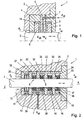
- Fig. 1 is a sealing arrangement 1 for sealing an axially reciprocating piston rod 3 of a reciprocating compressor against a sealed pressure p d of a working medium, for example, the cylinder pressure shown.
- the sealing arrangement 1 is arranged in a stationary housing part 2 of the compressor and seals between this housing part 2 and the moving piston rod 3.
- the sealing arrangement 1 comprises two L-shaped chamber disks 4, 5, which are separated axially by a separating disk 6 in the exemplary embodiment shown.
- the L-shaped chamber discs 4, 5 and the cutting disc 6 are arranged axially adjacent to each other and radially spaced from the piston rod 3, to prevent a rubbing of the piston rod 3 to the chamber discs 4, 5 and to a mobility of the piston rod 3 transverse to the lifting movement ( indicated by the double arrow).
- the cutting disc 6 but also be omitted. But there are also other designs, eg with T-shaped cutting discs, conceivable.
- a flange can also be provided radially on the outside, by means of which the sealing arrangement 1 can be fastened to the housing part 2.
- the chamber discs 4, 5 and optionally the cutting disc 6 can be held together in a known manner by a continuous bolt. This arrangement results between the L-shaped chamber discs 4, 5, optionally the cutting disc 6 and the piston rod 3, a recess 10.
- a first and second sealing element 8, 9 are arranged, wherein the sealing elements 8, 9 by the acting Pressure of a supplied into the recess 10 sealing medium respectively at the axial ends of the recess 10, so the radial limbs of the L-shaped chamber discs 4, 5, rest and are arranged axially separated from each other (the orientations "axially” and “radially” are on the orientation of the piston rod 3 related).
- the first and second sealing element 8, 9 are spaced apart radially from the chamber discs 4, 5, that is, from the axial limbs of the chamber discs 4, 5, and lie radially inwardly against the sealing surface on the piston rod 3.
- a supply line 7 is further provided, which is connected to the recess 10 and via which a sealing medium, such as an oil, under a pressure p oil , which is greater than the pressure to be sealed p d , fed into the recess 10 can be.
- a sealing medium such as an oil
- p oil > p d, max
- the pressure of the sealing medium is dynamically adapted to the pressure of the working medium, so that always applies p oil > p d .
- the sealing medium is thus enclosed by the sealing elements 8, 9 in the recess 10 and acts radially outward and axially on the sealing elements 8, 9, which are thus pressed radially inwardly to the piston rod 3 and axially to the chamber discs 4, 5 and thus seal ,
- the sealing elements 8, 9 are moved without affecting the sealing effect.
- sealing elements 8, 9 either known hydraulic sealing rings, such as e.g. a lip sealing ring or a compact sealing ring, with a sealing lip resting against the piston rod 3, or else well-known rigid, cut or segmented packing rings or packing ring combinations, such as e.g. a combination of a radially and tangentially cut packing ring can be used.
- hydraulic sealing rings can also be designed such that sealing medium which is pressed through the sealing lip during a stroke is "sucked back" again by the sealing lip during the counterstroke, so that in total there is no leakage of sealing medium through the hydraulic sealing ring.
- packing rings or packing ring combinations there is usually a slight leakage of sealing medium through the seal, which, however, is usually not a problem.
- packing rings usually also a standstill leakage, while a hydraulic sealing ring seals by the sealing medium pressure even at a standstill, at least as long as the sealing medium pressure is maintained.
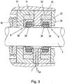
- the sealing arrangement 1 here comprises a plurality of successively arranged L-shaped chamber discs 20, 21, 22, 23, 24, wherein the L-shaped chamber discs 20, 21, 22, 23, 24 are aligned here all rectified, bringing the axial legs all in the same Direction. But there are also other designs, eg with T-shaped cutting discs, conceivable.
- this sealing arrangement 1 is closed in the axial direction by an end plate 25, which is formed as a flange for fastening in the housing part 2.
- the chamber discs 20, 21, 22, 23, 24 and the end plate 25 are in turn arranged radially spaced from the piston rod 3.
- recesses 30, 31, 32, 33, 34 are formed in which now sealing elements with different functions and axially spaced from each other can be arranged.
- the individual sealing elements are all arranged radially spaced from the respective radial ends of the recesses 30, 31, 32, 33, 34, so that the piston rod 3 remains freely movable transversely to the lifting movement.
- the actual sealing takes place by the sealing elements 8, 9, which are arranged in the recesses 31, 32 formed by three adjacent chamber discs 21, 22, 23, as above Fig. 1 described.
- the supply line 7 for the sealing medium can be performed by the radial leg of an L-shaped chamber disc 22.
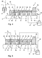
- a sealing element 8, 9, shown in detail in FIG Fig. 3 here in each case comprises an L-shaped rigid support ring 36 which rests on the radial leg of the axially outer chamber discs 21, 23 and radially spaced from the axial leg of the axially outer chamber discs 21, 23 is arranged.
- At the radial leg of the support ring 36 is axially on a hydraulic sealing ring 38 at.
- a resilient Mauab Whyinheit 39 for example, an O-ring can be further arranged.
- This Coab Whyinheit 39 serves to seal the secondary sealing surfaces, here for example between the radial leg of the support ring 36 and the hydraulic sealing ring 38, but also for pressing the hydraulic sealing ring 38 to the sealing surface of the piston rod 3.
- the use of an O-ring as Mauabêtinheit 39 is particularly advantageous because an elastic, non-compressible O-ring converts the upcoming sealing medium pressure into a radial contact pressure with which the sealing ring 38 is pressed against the piston rod 3.
- this Mauabêtinheit 39 can also be omitted, in this case would be the hydraulic Sealing ring 38 also abut the axial leg of the support ring 36 and seal this secondary sealing surface.
- the L-shaped support ring 36, optionally the Mauabêtinheit 39 and the hydraulic sealing ring 38 are axially spaced from the central radial leg of the chamber disc 22 so that the sealing medium, the sealing element 8, 9 for sealing axially against the respective radial leg of the chamber disc 21, 23 can press ,
- the sealing element 8, 9, here the arrangement of L-shaped support ring 36, optionally elastic support ring 39 and hydraulic sealing ring 38 while maintaining the sealing effect with the piston rod 3 moves.
- the third sealing element 11 may also be designed as a rigid or segmented packing ring or as a packing ring combination. The high working pressure p d of the working medium thus acts on this third sealing element 11 in the operational use of the sealing arrangement 1.
- This third sealing element 11 essentially serves, on the one hand, to prevent the penetration of dirt into the actual seal formed by the two sealing elements 8, 9 and, on the other hand, in the case of failure of the sealing element 8 by the third sealing element 11, still maintains a certain sealing effect can, whereby at least an unhindered leakage of sealing medium into the cylinder chamber can be prevented.
- a fourth sealing element 14 here again a combination of an L-shaped support ring, optionally Mauabêtinheit and hydraulic sealing ring as described above, respectively.
- this sealing element 14 on the one hand, a division of the effective pressure difference between the pressure p oil of the sealing medium and acting in the crankcase atmospheric pressure p at the sealing elements 9 and 14 is achieved, and on the other hand, this sealing element 14 again forms a certain security, if the sealing element should fail.
- a hydraulic sealing ring but can be used as a sealing element 14 in turn a rigid, cut or segmented packing ring or a packing ring combination of such packing rings.
- a fifth sealing element 15 here a scraper ring 17, which is arranged in a recess 34 of the last L-shaped chamber disc 24, completed.
- the differential pressure wiper ring 17 is arranged in an L-shaped rigid support ring 16 and can also be pressed by springs or other bias axially to the support ring 16 to prevent axial reciprocation of the scraper ring 17 ..
- adhering to the piston rod 3 sealing medium is removed from the Kolbestange 3. This excess sealing medium can be collected in the recess 34 and discharged from there by appropriate discharges and fed to a sealing medium reservoir.
- the fifth sealing element 15 prevents penetration of dirt into the actual seal formed by the two sealing elements 8, 9 and optionally sealing element 14.
- the third, fourth and fifth sealing elements 11, 14, 15 are optional in the sealing arrangement 1 and can be used in any combination depending on requirements and application.
- FIGS. 4 to 6 Further versions are in the FIGS. 4 to 6 shown.
- the cylinder is held in front of the first sealing element 8, the pressure on the suction pressure p s of the compressor.
- This has the advantage that only the (low) static suction pressure p s has to be sealed by the first and second sealing elements 8, 9.
- the (high) dynamic cylinder pressure p d -p s is reduced by a sealing element 11 located in front of it.
- the necessary pressure p oil of the sealing medium can therefore be correspondingly lowered.
- At the individual sealing elements 8, 9 is therefore also a lower pressure difference, whereby the requirements for the sealing elements 8, 9 can be reduced.
- compressor applications typically require 8,000 hours of operation without failure for the seal assembly 1.
- hydraulic sealing rings are unsuitable as sealing elements 8, 9, since they would not reach the required service life under such operating conditions.
- the first and second sealing element 8, 9 formed by two hydraulic sealing rings, such as Fig. 1 described.
- Cylinder side before and axially spaced from the first sealing element 8 is a third sealing element 11, here in the form of a packing ring combination arranged.
- the third sealing element 11 may also be designed as a rigid or segmented packing ring or as a packing ring combination. Since the first sealing element 8 and third sealing element 11 are arranged axially spaced from one another, a gap 49 is formed between these sealing elements 8, 11, which is bounded radially here by the first chamber disk 21.
- the pressure via a supply line 40 in the first chamber disc 21, which is connected via a feed line 45 with the suction pressure p s , for example, with the suction line 60 of the compressor, maintained at suction pressure p s .
- the static suction pressure p s acts in the intermediate space 49 between the first sealing element 8 and third sealing element 11 thus the static suction pressure p s acts.
- the sealing medium thus only needs to be sealed off from the suction pressure p s .
- the dynamic pressure difference p d - p s is degraded by the third sealing element 11, here a packing ring combination, which is substantially less pressure sensitive than a hydraulic sealing ring. With regard to the acting pressures, therefore, only more p oil > p s must be fulfilled.
- a fourth sealing element 14 in the form of a hydraulic sealing ring as above to Fig. 2 described
- a fifth sealing element 15 in the form of a scraper ring also as above to Fig. 2 described, provided. Regarding their function is to the description of Fig. 2 and 3 directed.
- the fourth sealing element 14 can also be omitted.
- the fifth sealing element 15 is, especially when using hydraulic sealing rings with "back suction" as described above, not mandatory. If present, the sealing medium adhering to the piston rod 3 is removed by the fifth sealing element 15 (scraper ring), so that substantially no sealing medium enters the crankcase.
- the retained sealing medium is fed via a sealing medium line 41 to a sealing medium reservoir 42.
- sealing medium is supplied under pressure p oil by means of a pump 43 via a feed line 44 to the feed 7. Any lost in the cylinder chamber sealing medium, especially when using a packing ring or a packing ring combination as the first sealing element 8, must be regularly refilled into the sealing medium reservoir.
- the suction pressure p s suddenly acts on one side of the sixth sealing element 8a, and the sealing medium pressure p oil on the other side, and the sixth sealing element 8a can be designed such that it is activated in this case and through the Pressure of the sealing medium p oil sealing against the piston rod 3 is pressed.
- the sixth sealing element 8a thus serves the safety and maintenance of the sealing effect in case of failure of the first sealing element 8a.
- a sixth sealing element 8a could also be used in a sealing arrangement as in FIG Fig. 2 shown used.
- a scraper ring is provided on the cylinder side, as in Fig. 6 shown.
- a seventh sealing element 50 in the form of a scraper ring is arranged between the first sealing element 8 and the third sealing element 11 in a further seventh chamber disk 51.
- the removed by the scraper ring of the piston rod 3 Dichimedium is discharged via a discharge line 48 from the recess 52 formed by the seventh chamber disc 51.
- the discharge line 48 opens here into a second sealing medium reservoir 46, which is held at suction pressure p s , as in Fig.
- the second sealing medium reservoir 46 may be connected via a throttle 53 and a connecting line 47 with the first sealing medium reservoir 42.
- the throttle 53 is necessary because the first sealing medium reservoir 42, as a rule, for example, is held by a vent to atmospheric pressure p at, and otherwise the sealing medium would freely flow into the first sealing medium reservoir 42nd.
- a scraper ring could also in a sealing arrangement 1 after the Fig. 2 be used. In this case, the scraper ring could be held without differential pressure, by the force acting in front of the scraper ring pressure through corresponding connecting holes in the scraper ring receiving recess is guided.
Landscapes
- Engineering & Computer Science (AREA)
- General Engineering & Computer Science (AREA)
- Mechanical Engineering (AREA)
- Sealing Devices (AREA)
- Compressor (AREA)
Claims (13)
- Dispositif d'étanchéité pour réaliser l'étanchéité d'une tige de piston (3) à mouvement alternatif d'un compresseur à piston, comprenant un premier (8) et un deuxième (9) élément d'étanchéité qui sont disposés avec un écartement axial dans un évidement (10, 31, 32) du dispositif d'étanchéité (1), dans lequel les éléments d'étanchéité (8, 9) sont disposés chacun à une extrémité axiale de l'évidement (10, 31, 32) et en appui contre la tige de piston (3) et, dans le dispositif d'étanchéité (1), est disposée une conduite d'amenée (7) pour un fluide d'étanchéité, qui est reliée à l'évidement (10, 31, 32), le premier et le deuxième élément d'étanchéité (8, 9) étant espacés dans la direction radiale de l'extrémité radiale de l'évidement (10, 31, 32), de sorte que le milieu d'étanchéité agit axialement et sur la surface périphérique radialement extérieure du premier et du deuxième élément d'étanchéité (8, 9), caractérisé en ce que, à une première extrémité axiale du dispositif d'étanchéité (1) est disposé, dans un autre évidement, appelé troisième évidement, (30) du dispositif d'étanchéité (1), un troisième élément d'étanchéité (11) qui est réalisé sous la forme d'une bague de garniture ou d'une combinaison de bagues de garniture, et une bague racleuse (50) est disposée entre le premier élément d'étanchéité (8) et le troisième élément d'étanchéité (11), dans un autre évidement, appelé septième évidement, (52) du dispositif d'étanchéité (1), le dispositif d'étanchéité (1) étant construit de telle sorte que cette bague racleuse (50) soit tenue sans pression différentielle, dans lequel la pression dans le septième évidement (52) est combinée, dans la mise en service, à la pression opérant devant la bague racleuse (50) si bien que la bague racleuse (50) est tenue sans pression différentielle.
- Dispositif d'étanchéité selon la revendication 1, caractérisé en ce que, dans le dispositif d'étanchéité (1), deux rondelles à chambre en forme de L (4, 5, 21, 22) sont disposées en appui axial l'une contre l'autre et, à chaque fois, un élément d'étanchéité (8, 9) est disposé dans l'évidement (10, 31, 32) formé par les rondelles à chambre en forme de L (4, 5, 21, 22).
- Dispositif d'étanchéité selon la revendication 2, caractérisé en ce que les deux rondelles à chambre en forme de L (21, 22) sont orientées dans le même sens de sorte que la branche radiale d'une rondelle à chambre en forme de L (22) est disposée entre les deux éléments d'étanchéité (8, 9) et que les deux éléments d'étanchéité (8, 9) sont espacés d'un écartement axial par cette branche radiale.
- Dispositif d'étanchéité selon la revendication 3, caractérisé en ce que la conduite d'amenée (7) est disposée dans cette branche radiale médiane.
- Dispositif d'étanchéité selon l'une des revendications 1 à 4, caractérisé en ce qu'il utilise, pour au moins un élément d'étanchéité (8, 9), une bague de garniture rigide, segmentée ou coupée, ou une combinaison de bagues de garniture de ce type.
- Dispositif d'étanchéité selon l'une des revendications 1 à 4, caractérisé en ce qu'il utilise, pour au moins un élément d'étanchéité (8, 9), une bague d'étanchéité hydraulique (38).
- Dispositif d'étanchéité selon la revendication 6, caractérisé en ce que la bague d'étanchéité hydraulique (38) est disposée en appui axial dans une bague d'appui rigide en forme de L (36) et la bague d'appui (36) est espacée radialement de l'extrémité radiale de l'évidement (10, 31, 32).
- Dispositif d'étanchéité selon la revendication 7, caractérisé en ce qu'une unité d'étanchéité secondaire (39) est disposée entre la bague d'appui (36) et la bague d'étanchéité hydraulique (38).
- Dispositif d'étanchéité selon l'une des revendications 1 à 8, caractérisé en ce que, dans un espace intermédiaire (49) formé entre le premier élément d'étanchéité (8) et le troisième élément d'étanchéité (11), débouche une conduite d'amenée (40) qui, dans l'utilisation conforme pour le fonctionnement, est reliée à la pression d'aspiration (pa) du compresseur à piston, de sorte que la pression d'aspiration (ps) règne dans cet espace intermédiaire (49).
- Dispositif d'étanchéité selon l'une des revendications 1 à 9, caractérisé en ce qu'à une deuxième extrémité axiale du dispositif d'étanchéité (1), est disposé, dans un autre évidement, ou quatrième évidement (33), du dispositif d'étanchéité (1), un quatrième élément d'étanchéité (14) qui est constitué par une bague de garniture ou une combinaison de bagues de garniture ou par une bague d'étanchéité hydraulique.
- Dispositif d'étanchéité selon l'une des revendications 1 à 10, caractérisé en ce qu'à une deuxième extrémité axiale du dispositif d'étanchéité (1), est disposé, dans un autre évidement, ou cinquième évidement, (34) du dispositif d'étanchéité (1), un cinquième élément d'étanchéité (15) qui est constitué par une bague racleuse (17).
- Dispositif d'étanchéité selon l'une des revendications 10 ou 11, caractérisé en ce que la bague d'étanchéité hydraulique et/ou la bague racleuse (17) est ou sont disposées dans un évidement formé par une bague d'appui en forme de L (16).
- Dispositif d'étanchéité selon l'une des revendications 1 à 12, caractérisé en ce qu'entre le premier élément d'étanchéité (8) et le deuxième élément d'étanchéité (9), est disposée, dans un autre évidement, ou sixième évidement (31 a), du dispositif d'étanchéité (1), un autre élément d'étanchéité ou sixième élément d'étanchéité (8a) qui est constitué par une bague de garniture ou une combinaison de bagues de garniture, ou par une bague d'étanchéité hydraulique, et qui, dans l'utilisation conforme pour le fonctionnement, est espacée radialement de la tige de piston (3).
Applications Claiming Priority (2)
| Application Number | Priority Date | Filing Date | Title |
|---|---|---|---|
| AT0003909A AT507564B1 (de) | 2009-01-12 | 2009-01-12 | Dichtanordnung zur abdichtung einer kolbenstange eines kolbenkompressors |
| PCT/EP2010/050216 WO2010079227A1 (fr) | 2009-01-12 | 2010-01-11 | Dispositif d'étanchéité permettant de rendre étanche une tige de piston d'un compresseur à piston |
Publications (3)
| Publication Number | Publication Date |
|---|---|
| EP2376819A1 EP2376819A1 (fr) | 2011-10-19 |
| EP2376819B1 EP2376819B1 (fr) | 2014-03-26 |
| EP2376819B2 true EP2376819B2 (fr) | 2017-10-11 |
Family
ID=42126513
Family Applications (1)
| Application Number | Title | Priority Date | Filing Date |
|---|---|---|---|
| EP10700059.8A Not-in-force EP2376819B2 (fr) | 2009-01-12 | 2010-01-11 | Dispositif d'étanchéité permettant de rendre étanche une tige de piston d'un compresseur à piston |
Country Status (7)
| Country | Link |
|---|---|
| US (1) | US9027934B2 (fr) |
| EP (1) | EP2376819B2 (fr) |
| JP (1) | JP5538430B2 (fr) |
| CN (1) | CN102272492B (fr) |
| AT (1) | AT507564B1 (fr) |
| BR (1) | BRPI1007292A2 (fr) |
| WO (1) | WO2010079227A1 (fr) |
Families Citing this family (45)
| Publication number | Priority date | Publication date | Assignee | Title |
|---|---|---|---|---|
| AT507564B1 (de) | 2009-01-12 | 2010-06-15 | Hoerbiger Kompressortech Hold | Dichtanordnung zur abdichtung einer kolbenstange eines kolbenkompressors |
| GB201021266D0 (en) * | 2010-12-14 | 2011-01-26 | Crane John Uk Ltd | Seals |
| AT510171B1 (de) * | 2011-02-17 | 2012-02-15 | Hoerbiger Kompressortech Hold | Dichtpackung für eine hin- und hergehende kolbenstange eines kolbenkompressors |
| NL2006718C2 (en) * | 2011-05-04 | 2012-11-06 | Thomassen Compression Syst Bv | Piston compressor for compressing gas. |
| DE102011119011A1 (de) * | 2011-11-14 | 2013-05-16 | Hydac Technology Gmbh | Gaszylinder, insbesondere Hochdruck-Gaszylinder |
| AT512945B1 (de) * | 2012-06-04 | 2013-12-15 | Hoerbiger Kompressortech Hold | Dichtanordnung zur Abdichtung einer hin- und hergehenden Kolbenstange eines Kolbenkompressors |
| AT513495B1 (de) * | 2012-11-28 | 2014-05-15 | Hoerbiger Kompressortech Hold | Dichtanordnung zur Abdichtung einer hin- und hergehenden Kolbenstange eines Kolbenkompressors |
| CN105247528B (zh) | 2013-06-27 | 2018-05-18 | 英特尔公司 | 连续多因素认证 |
| AT514335B1 (de) * | 2013-07-10 | 2014-12-15 | Hoerbiger Kompressortech Hold | Dichtanordnung zur Abdichtung einer hin- und hergehenden Kolbenstange eines Kolbenkompressors |
| AT513836B1 (de) * | 2013-09-23 | 2014-08-15 | Hoerbiger Kompressortech Hold | Kompressor mit und Verfahren zur Spülung des Kompressorgehäuses mit Spülgas |
| CN203730353U (zh) * | 2014-02-27 | 2014-07-23 | 讯凯国际股份有限公司 | 薄型化轴向气隙式风扇 |
| WO2016087326A1 (fr) * | 2014-12-05 | 2016-06-09 | Nuovo Pignone Srl | Boîte à garniture pour machine à piston alternatif et son procédé d'assemblage |
| DE102014226429A1 (de) * | 2014-12-18 | 2016-06-23 | Eagleburgmann Germany Gmbh & Co. Kg | Wellendichtungsanordnung einer Fluidmaschine sowie Verfahren zur Abdichtung einer Welle einer Fluidmaschine |
| US20190136858A1 (en) * | 2015-03-30 | 2019-05-09 | Hicor Technologies, Inc. | Compressor with liquid injection cooling |
| CN104879499B (zh) * | 2015-05-04 | 2018-01-23 | 西安近代化学研究所 | 一种防尘密封装置 |
| JP6553969B2 (ja) * | 2015-07-23 | 2019-07-31 | 株式会社日立製作所 | 往復圧縮機 |
| DE102016210731A1 (de) * | 2016-06-16 | 2017-12-21 | Robert Bosch Gmbh | Förderpumpe für kryogene Kraftstoffe |
| JP7227125B2 (ja) * | 2016-08-26 | 2023-02-21 | ブルクハルト コンプレッション アーゲー | オイルワイパパッキンおよびオイルワイパパッキンを取り付ける方法 |
| CN107559186A (zh) * | 2017-09-06 | 2018-01-09 | 芜湖精达机械制造有限公司 | 一种海水泵管路连接装置 |
| FR3072136B1 (fr) * | 2017-10-10 | 2021-11-19 | Atlas Copco Crepelle S A S | Systeme d'etancheisation d'une tige de piston pour une machine a mouvement alternatif et procede pour l'etancheisation d'une telle tige de piston |
| DE102018100637B3 (de) | 2018-01-12 | 2019-06-06 | Dürr Systems Ag | Dichtung und Beschichtungsmittelpumpe mit einer solchen Dichtung |
| JP7176846B2 (ja) * | 2018-03-02 | 2022-11-22 | 極東開発工業株式会社 | コンクリートポンプ |
| CN108799061A (zh) * | 2018-08-15 | 2018-11-13 | 安徽士必达液压器材有限公司 | 一种气体增压泵用超高压活塞 |
| AT521716B1 (de) | 2018-09-20 | 2020-07-15 | Hoerbiger Wien Gmbh | Ölabstreifring für eine Kolbenstange |
| CN109442042B (zh) * | 2018-10-19 | 2023-10-31 | 杭州加一包装技术有限责任公司 | 一种用于粉体环境下的机械部件气体密封结构 |
| CN109323004A (zh) * | 2018-11-21 | 2019-02-12 | 中国航发西安动力控制科技有限公司 | 一种带过渡压力腔的减小间隙泄漏结构 |
| CN109237029B (zh) * | 2018-11-30 | 2022-02-25 | 恒天九五重工有限公司 | 一种旋转密封装置 |
| ES2930042T3 (es) | 2019-01-29 | 2022-12-05 | Hoerbiger Wien Gmbh | Anillo de empaquetadura con abertura de desgaste |
| JP7693547B2 (ja) | 2019-01-29 | 2025-06-17 | ヘルビガー ウィーン ゲゼルシャフト ミット ベシュレンクテル ハフツング | 傾斜したリリーフ開口を備えたパッキンリング |
| CN113474579B (zh) | 2019-01-29 | 2025-01-10 | 贺尔碧格维恩有限公司 | 具有卸荷开口的密封环 |
| US11761538B2 (en) * | 2020-02-06 | 2023-09-19 | Tamar (R.C.) Technologies Development Ltd. | Sealing system for rotary shaft |
| US11788541B2 (en) | 2020-05-18 | 2023-10-17 | Dover Pumps & Process Solutions Segment, Inc. | High pressure gas sealing |
| EP4145025B1 (fr) | 2020-09-30 | 2026-05-06 | Sany Automobile Manufacturing Co., Ltd. | Appareil de résistance à l'eau, système de pompage, machine de pompage et procédé de nettoyage |
| CN112197003A (zh) * | 2020-10-13 | 2021-01-08 | 自贡东方通用压缩机有限公司 | 一种活塞式压缩机密封机构 |
| DE102020134381A1 (de) * | 2020-12-21 | 2022-06-23 | NEUMAN & ESSER Deutschland GmbH & Co. KG Vertrieb und Anlagentechnik | Kompressor, Scheibenkörper und Dichtung |
| US12313052B2 (en) | 2021-06-08 | 2025-05-27 | Dover Pumps & Process Solutions Segment, Inc. | Expansion chamber for progressive sealing system |
| CN113374682B (zh) * | 2021-07-15 | 2022-05-13 | 西南石油大学 | 一种压裂泵液力端柱塞孔密封结构 |
| CN113915335A (zh) * | 2021-10-14 | 2022-01-11 | 安瑞科(蚌埠)压缩机有限公司 | 一种活塞式压缩机无泄漏密封装置 |
| DE102022202008A1 (de) * | 2022-02-28 | 2023-08-31 | Van Halteren Technologies Boxtel B.V. | Dichtungssystem für einen Verdichter und Verdichter |
| US12435716B2 (en) * | 2022-05-09 | 2025-10-07 | Hoerbiger Wien Gmbh | Pressure packing for a reciprocating piston compressor with buffer gas barrier |
| CN115962281B (zh) * | 2022-07-18 | 2026-03-20 | 江苏汉苏机械股份有限公司 | 活塞杆密封改良结构 |
| CN115789250B (zh) * | 2022-11-09 | 2026-01-16 | 浙江神太太阳能股份有限公司 | 一种快装式罐组合密封盖及热水器内筒 |
| CN116816637A (zh) * | 2023-07-31 | 2023-09-29 | 新疆大全新能源股份有限公司 | 往复式氢气压缩机机封气排放回收利用系统 |
| EP4603726B1 (fr) | 2024-02-13 | 2026-07-29 | WinGD Ltd. | Dispositif d'étanchéité |
| DE102024121403A1 (de) * | 2024-07-26 | 2026-01-29 | Eagleburgmann Germany Gmbh & Co. Kg | Dichtsystem zur Abdichtung zwischen einem rotierenden Bauteil und einem stationären Bauteil |
Family Cites Families (39)
| Publication number | Priority date | Publication date | Assignee | Title |
|---|---|---|---|---|
| US2191265A (en) * | 1936-06-06 | 1940-02-20 | Harley T Wheeler | Segmental metallic packing ring |
| US2714028A (en) * | 1953-07-29 | 1955-07-26 | Morganite Inc | Sealing and packing rings |
| DE1132681B (de) | 1958-10-24 | 1962-07-05 | Linde Eismasch Ag | Stopfbuechsenanordnung fuer die Kolbenstange von Trockenlaufverdichter |
| DE1144873B (de) | 1960-09-07 | 1963-03-07 | Linde Eismasch Ag | Stopfbuechsenanordnung fuer die Kolbenstange von Trockenlaufverdichtern |
| US3194568A (en) * | 1961-06-16 | 1965-07-13 | Dresser Ind | Stuffing box with cooling and vent means |
| US3271037A (en) * | 1963-04-01 | 1966-09-06 | Garlock Inc | Pressure-balanced segmental packing rings |
| US3216651A (en) * | 1963-07-01 | 1965-11-09 | Battelle Development Corp | Seal |
| US3542374A (en) * | 1968-04-24 | 1970-11-24 | Worthington Corp | Packing for piston rods in high pressure nonlube reciprocating compressors |
| US3544118A (en) * | 1968-10-01 | 1970-12-01 | Koppers Co Inc | Pressure balanced shaft seal |
| US3860270A (en) * | 1971-09-30 | 1975-01-14 | Hydrotech Int Inc | Apparatus for effecting a connection to a tubular member or the like |
| US4093239A (en) * | 1976-01-21 | 1978-06-06 | Nippon Piston Ring Co., Ltd. | Piston rod sealing arrangement for a stirling engine |
| JPS5442548A (en) | 1977-09-10 | 1979-04-04 | Kenji Asano | Leak seal liquid return apparatus for stirling engine |
| JPS54140165U (fr) * | 1978-03-23 | 1979-09-28 | ||
| US4350349A (en) | 1981-02-12 | 1982-09-21 | Harry A. Robertson, Jr. | Rod packing |
| US4453176A (en) | 1981-12-31 | 1984-06-05 | International Business Machines Corporation | LSI Chip carrier with buried repairable capacitor with low inductance leads |
| JPS58119664U (ja) * | 1982-02-10 | 1983-08-15 | 三井造船株式会社 | 密封装置 |
| US4514148A (en) | 1982-11-01 | 1985-04-30 | Carter Controls, Inc. | Hydraulically actuated pump |
| US4469017A (en) * | 1983-02-23 | 1984-09-04 | Dover Corporation | Static leak seal assembly for use in fluid containing machinery |
| NL8303794A (nl) | 1983-11-03 | 1985-06-03 | Stork Serv Bv | Inrichting voor het behandelen van een wand, zoals een scheepswand. |
| JPS60114373U (ja) * | 1984-01-12 | 1985-08-02 | エヌオーケー株式会社 | 密封装置 |
| JPS60172058A (ja) | 1984-02-17 | 1985-09-05 | Ricoh Co Ltd | 現像装置 |
| DE3577595D1 (de) | 1984-04-25 | 1990-06-13 | Tanken Seiko Kk | Dichtungsvorrichtung fuer pulver. |
| JPS60172058U (ja) * | 1984-04-25 | 1985-11-14 | 炭研精工株式会社 | セグメントシ−ル構造 |
| GB2185542B (en) * | 1985-07-13 | 1988-05-25 | Crane Packing Ltd | Gas tight seal |
| JPS6375668A (ja) | 1986-09-19 | 1988-04-06 | Hitachi Ltd | フロ−インジエクシヨン分析装置 |
| JPS6375668U (fr) * | 1986-11-06 | 1988-05-20 | ||
| US5209495A (en) * | 1990-09-04 | 1993-05-11 | Palmour Harold H | Reciprocating rod pump seal assembly |
| DE4205862C1 (fr) * | 1992-02-26 | 1993-06-17 | Fa. Carl Freudenberg, 6940 Weinheim, De | |
| DE4211192A1 (de) * | 1992-04-03 | 1993-10-07 | Schreiter Eberhard | Einrichtung zur Überleitung von Druckmedien von einem feststehenden Gehäuse auf eine rotierende Welle |
| JPH0618664A (ja) | 1992-07-06 | 1994-01-28 | Matsushita Electric Ind Co Ltd | 車両用側方監視装置 |
| US5607165A (en) * | 1995-06-07 | 1997-03-04 | Cooper Cameron Corporation | Sealing system for a valve having biassed sealant under pressure |
| JP3687241B2 (ja) * | 1996-12-13 | 2005-08-24 | 株式会社日立製作所 | 封水装置およびその封水装置を備えた水車 |
| US6286837B1 (en) * | 1999-08-24 | 2001-09-11 | Delaware Capital Formation, Inc. | Compressor piston rod packing ring set |
| AT411384B (de) | 2000-04-10 | 2003-12-29 | Hoerbiger Ventilwerke Gmbh | Dichtring-kombination |
| JP2001066757A (ja) * | 2000-08-07 | 2001-03-16 | Seiko Epson Corp | 露光方法 |
| US6932351B1 (en) * | 2003-02-07 | 2005-08-23 | William L. Mowll | Packing case for cooling compressors and other machinery |
| US7118114B2 (en) | 2003-05-15 | 2006-10-10 | Woodward Governor Company | Dynamic sealing arrangement for movable shaft |
| DE102005034908A1 (de) | 2005-07-26 | 2007-02-01 | Linde Ag | Hermetisches Dichtungssystem |
| AT507564B1 (de) | 2009-01-12 | 2010-06-15 | Hoerbiger Kompressortech Hold | Dichtanordnung zur abdichtung einer kolbenstange eines kolbenkompressors |
-
2009
- 2009-01-12 AT AT0003909A patent/AT507564B1/de not_active IP Right Cessation
-
2010
- 2010-01-11 BR BRPI1007292A patent/BRPI1007292A2/pt active Search and Examination
- 2010-01-11 JP JP2011544881A patent/JP5538430B2/ja not_active Expired - Fee Related
- 2010-01-11 CN CN201080004289.4A patent/CN102272492B/zh not_active Expired - Fee Related
- 2010-01-11 EP EP10700059.8A patent/EP2376819B2/fr not_active Not-in-force
- 2010-01-11 WO PCT/EP2010/050216 patent/WO2010079227A1/fr not_active Ceased
- 2010-01-11 US US13/138,140 patent/US9027934B2/en not_active Expired - Fee Related
Also Published As
| Publication number | Publication date |
|---|---|
| BRPI1007292A2 (pt) | 2016-10-25 |
| JP5538430B2 (ja) | 2014-07-02 |
| AT507564B1 (de) | 2010-06-15 |
| EP2376819B1 (fr) | 2014-03-26 |
| AT507564A4 (de) | 2010-06-15 |
| US9027934B2 (en) | 2015-05-12 |
| JP2012515298A (ja) | 2012-07-05 |
| CN102272492A (zh) | 2011-12-07 |
| EP2376819A1 (fr) | 2011-10-19 |
| US20110298183A1 (en) | 2011-12-08 |
| CN102272492B (zh) | 2015-03-11 |
| WO2010079227A1 (fr) | 2010-07-15 |
Similar Documents
| Publication | Publication Date | Title |
|---|---|---|
| EP2376819B1 (fr) | Dispositif d'étanchéité permettant de rendre étanche une tige de piston d'un compresseur à piston | |
| EP2489907B1 (fr) | Dispositif d'étanchéité pour une tige de piston à mouvement de va-et-vient d'un compresseur à piston | |
| DE69219507T2 (de) | Druck entlastende Abstreifdichtungsanordnung | |
| EP2027403B1 (fr) | Structure d'étanchéite pour décompression | |
| AT513495B1 (de) | Dichtanordnung zur Abdichtung einer hin- und hergehenden Kolbenstange eines Kolbenkompressors | |
| EP2056003B1 (fr) | Bague d'étanchéité en plusieurs parties | |
| AT513836B1 (de) | Kompressor mit und Verfahren zur Spülung des Kompressorgehäuses mit Spülgas | |
| EP0356619B1 (fr) | Garniture étanche à anneau glissant | |
| EP3077710B1 (fr) | Agencement d'étanchéification | |
| EP2827026B1 (fr) | Dispositif d'étanchéité dotée d'une bague d'étanchéité | |
| AT507055B1 (de) | Kolben mit kolbenringen und stützringen | |
| AT514335B1 (de) | Dichtanordnung zur Abdichtung einer hin- und hergehenden Kolbenstange eines Kolbenkompressors | |
| DE102007048242A1 (de) | Kolbenpumpen-Unterbaugruppe, Kolbenpumpe und Montageverfahren hierfür | |
| DE102011119437A1 (de) | Federspeicherbremszylinder, beispielsweise für Kraftfahrzeugbremsen | |
| DE202018102291U1 (de) | Dichtungseinheit | |
| EP0067239B1 (fr) | Disposition d'échanchéité aux boîtes à labyrinthe pour tiges de piston de cylindres de charge à fluide étant logées hydrostatiquement | |
| EP3149366B1 (fr) | Bague d'étanchéité ou segment racleur | |
| WO2006061061A1 (fr) | Cylindre hydraulique, notamment pour une pompe d'extraction de petrole | |
| EP2607756B1 (fr) | Joint avec fonction de détente | |
| AT504522A4 (de) | Dichtungsanordnung | |
| DE102011081654A1 (de) | Anordnung zur kolbenstangenseitigen Abdichtung eines Geberzylinders | |
| DE102013109374B4 (de) | Bremszylinder mit Stangendichtungsanordnung | |
| DE19639798C5 (de) | Einzel-Abstreiferanordnung | |
| DE4415119C2 (de) | Gleitringdichtung | |
| DE102025105132A1 (de) | Dichtungsanordnung |
Legal Events
| Date | Code | Title | Description |
|---|---|---|---|
| PUAI | Public reference made under article 153(3) epc to a published international application that has entered the european phase |
Free format text: ORIGINAL CODE: 0009012 |
|
| 17P | Request for examination filed |
Effective date: 20110705 |
|
| AK | Designated contracting states |
Kind code of ref document: A1 Designated state(s): AT BE BG CH CY CZ DE DK EE ES FI FR GB GR HR HU IE IS IT LI LT LU LV MC MK MT NL NO PL PT RO SE SI SK SM TR |
|
| DAX | Request for extension of the european patent (deleted) | ||
| 17Q | First examination report despatched |
Effective date: 20120330 |
|
| RIC1 | Information provided on ipc code assigned before grant |
Ipc: F16J 15/56 20060101ALI20131011BHEP Ipc: F04B 53/16 20060101ALI20131011BHEP Ipc: F16J 15/40 20060101ALI20131011BHEP Ipc: F04B 53/14 20060101ALI20131011BHEP Ipc: F04B 39/00 20060101ALI20131011BHEP Ipc: F16J 15/44 20060101ALI20131011BHEP Ipc: F16J 15/24 20060101ALI20131011BHEP Ipc: F16J 15/00 20060101AFI20131011BHEP |
|
| GRAP | Despatch of communication of intention to grant a patent |
Free format text: ORIGINAL CODE: EPIDOSNIGR1 |
|
| INTG | Intention to grant announced |
Effective date: 20131125 |
|
| GRAP | Despatch of communication of intention to grant a patent |
Free format text: ORIGINAL CODE: EPIDOSNIGR1 |
|
| INTG | Intention to grant announced |
Effective date: 20140120 |
|
| GRAS | Grant fee paid |
Free format text: ORIGINAL CODE: EPIDOSNIGR3 |
|
| GRAA | (expected) grant |
Free format text: ORIGINAL CODE: 0009210 |
|
| AK | Designated contracting states |
Kind code of ref document: B1 Designated state(s): AT BE BG CH CY CZ DE DK EE ES FI FR GB GR HR HU IE IS IT LI LT LU LV MC MK MT NL NO PL PT RO SE SI SK SM TR |
|
| REG | Reference to a national code |
Ref country code: GB Ref legal event code: FG4D Free format text: NOT ENGLISH |
|
| REG | Reference to a national code |
Ref country code: CH Ref legal event code: EP |
|
| REG | Reference to a national code |
Ref country code: AT Ref legal event code: REF Ref document number: 659174 Country of ref document: AT Kind code of ref document: T Effective date: 20140415 Ref country code: CH Ref legal event code: NV Representative=s name: ISLER AND PEDRAZZINI AG, CH |
|
| REG | Reference to a national code |
Ref country code: IE Ref legal event code: FG4D Free format text: LANGUAGE OF EP DOCUMENT: GERMAN |
|
| REG | Reference to a national code |
Ref country code: DE Ref legal event code: R096 Ref document number: 502010006471 Country of ref document: DE Effective date: 20140508 |
|
| PG25 | Lapsed in a contracting state [announced via postgrant information from national office to epo] |
Ref country code: LT Free format text: LAPSE BECAUSE OF FAILURE TO SUBMIT A TRANSLATION OF THE DESCRIPTION OR TO PAY THE FEE WITHIN THE PRESCRIBED TIME-LIMIT Effective date: 20140326 Ref country code: NO Free format text: LAPSE BECAUSE OF FAILURE TO SUBMIT A TRANSLATION OF THE DESCRIPTION OR TO PAY THE FEE WITHIN THE PRESCRIBED TIME-LIMIT Effective date: 20140626 |
|
| REG | Reference to a national code |
Ref country code: NL Ref legal event code: VDEP Effective date: 20140326 |
|
| REG | Reference to a national code |
Ref country code: LT Ref legal event code: MG4D |
|
| PG25 | Lapsed in a contracting state [announced via postgrant information from national office to epo] |
Ref country code: SE Free format text: LAPSE BECAUSE OF FAILURE TO SUBMIT A TRANSLATION OF THE DESCRIPTION OR TO PAY THE FEE WITHIN THE PRESCRIBED TIME-LIMIT Effective date: 20140326 Ref country code: FI Free format text: LAPSE BECAUSE OF FAILURE TO SUBMIT A TRANSLATION OF THE DESCRIPTION OR TO PAY THE FEE WITHIN THE PRESCRIBED TIME-LIMIT Effective date: 20140326 |
|
| PG25 | Lapsed in a contracting state [announced via postgrant information from national office to epo] |
Ref country code: LV Free format text: LAPSE BECAUSE OF FAILURE TO SUBMIT A TRANSLATION OF THE DESCRIPTION OR TO PAY THE FEE WITHIN THE PRESCRIBED TIME-LIMIT Effective date: 20140326 Ref country code: HR Free format text: LAPSE BECAUSE OF FAILURE TO SUBMIT A TRANSLATION OF THE DESCRIPTION OR TO PAY THE FEE WITHIN THE PRESCRIBED TIME-LIMIT Effective date: 20140326 |
|
| PG25 | Lapsed in a contracting state [announced via postgrant information from national office to epo] |
Ref country code: BG Free format text: LAPSE BECAUSE OF FAILURE TO SUBMIT A TRANSLATION OF THE DESCRIPTION OR TO PAY THE FEE WITHIN THE PRESCRIBED TIME-LIMIT Effective date: 20140626 Ref country code: IS Free format text: LAPSE BECAUSE OF FAILURE TO SUBMIT A TRANSLATION OF THE DESCRIPTION OR TO PAY THE FEE WITHIN THE PRESCRIBED TIME-LIMIT Effective date: 20140726 Ref country code: CY Free format text: LAPSE BECAUSE OF FAILURE TO SUBMIT A TRANSLATION OF THE DESCRIPTION OR TO PAY THE FEE WITHIN THE PRESCRIBED TIME-LIMIT Effective date: 20140326 Ref country code: RO Free format text: LAPSE BECAUSE OF FAILURE TO SUBMIT A TRANSLATION OF THE DESCRIPTION OR TO PAY THE FEE WITHIN THE PRESCRIBED TIME-LIMIT Effective date: 20140326 Ref country code: CZ Free format text: LAPSE BECAUSE OF FAILURE TO SUBMIT A TRANSLATION OF THE DESCRIPTION OR TO PAY THE FEE WITHIN THE PRESCRIBED TIME-LIMIT Effective date: 20140326 Ref country code: NL Free format text: LAPSE BECAUSE OF FAILURE TO SUBMIT A TRANSLATION OF THE DESCRIPTION OR TO PAY THE FEE WITHIN THE PRESCRIBED TIME-LIMIT Effective date: 20140326 Ref country code: EE Free format text: LAPSE BECAUSE OF FAILURE TO SUBMIT A TRANSLATION OF THE DESCRIPTION OR TO PAY THE FEE WITHIN THE PRESCRIBED TIME-LIMIT Effective date: 20140326 |
|
| PG25 | Lapsed in a contracting state [announced via postgrant information from national office to epo] |
Ref country code: ES Free format text: LAPSE BECAUSE OF FAILURE TO SUBMIT A TRANSLATION OF THE DESCRIPTION OR TO PAY THE FEE WITHIN THE PRESCRIBED TIME-LIMIT Effective date: 20140326 Ref country code: SK Free format text: LAPSE BECAUSE OF FAILURE TO SUBMIT A TRANSLATION OF THE DESCRIPTION OR TO PAY THE FEE WITHIN THE PRESCRIBED TIME-LIMIT Effective date: 20140326 Ref country code: PL Free format text: LAPSE BECAUSE OF FAILURE TO SUBMIT A TRANSLATION OF THE DESCRIPTION OR TO PAY THE FEE WITHIN THE PRESCRIBED TIME-LIMIT Effective date: 20140326 |
|
| REG | Reference to a national code |
Ref country code: DE Ref legal event code: R026 Ref document number: 502010006471 Country of ref document: DE |
|
| PG25 | Lapsed in a contracting state [announced via postgrant information from national office to epo] |
Ref country code: PT Free format text: LAPSE BECAUSE OF FAILURE TO SUBMIT A TRANSLATION OF THE DESCRIPTION OR TO PAY THE FEE WITHIN THE PRESCRIBED TIME-LIMIT Effective date: 20140728 |
|
| PLBI | Opposition filed |
Free format text: ORIGINAL CODE: 0009260 |
|
| PG25 | Lapsed in a contracting state [announced via postgrant information from national office to epo] |
Ref country code: DK Free format text: LAPSE BECAUSE OF FAILURE TO SUBMIT A TRANSLATION OF THE DESCRIPTION OR TO PAY THE FEE WITHIN THE PRESCRIBED TIME-LIMIT Effective date: 20140326 |
|
| PLAX | Notice of opposition and request to file observation + time limit sent |
Free format text: ORIGINAL CODE: EPIDOSNOBS2 |
|
| 26 | Opposition filed |
Opponent name: STASSKOL GMBH Effective date: 20141223 Opponent name: BURCKHARDT COMPRESSION AG Effective date: 20150105 |
|
| REG | Reference to a national code |
Ref country code: DE Ref legal event code: R026 Ref document number: 502010006471 Country of ref document: DE Effective date: 20141223 |
|
| PLAF | Information modified related to communication of a notice of opposition and request to file observations + time limit |
Free format text: ORIGINAL CODE: EPIDOSCOBS2 |
|
| PG25 | Lapsed in a contracting state [announced via postgrant information from national office to epo] |
Ref country code: BE Free format text: LAPSE BECAUSE OF NON-PAYMENT OF DUE FEES Effective date: 20150131 |
|
| PLBB | Reply of patent proprietor to notice(s) of opposition received |
Free format text: ORIGINAL CODE: EPIDOSNOBS3 |
|
| PG25 | Lapsed in a contracting state [announced via postgrant information from national office to epo] |
Ref country code: SI Free format text: LAPSE BECAUSE OF FAILURE TO SUBMIT A TRANSLATION OF THE DESCRIPTION OR TO PAY THE FEE WITHIN THE PRESCRIBED TIME-LIMIT Effective date: 20140326 |
|
| PG25 | Lapsed in a contracting state [announced via postgrant information from national office to epo] |
Ref country code: LU Free format text: LAPSE BECAUSE OF FAILURE TO SUBMIT A TRANSLATION OF THE DESCRIPTION OR TO PAY THE FEE WITHIN THE PRESCRIBED TIME-LIMIT Effective date: 20150111 |
|
| PG25 | Lapsed in a contracting state [announced via postgrant information from national office to epo] |
Ref country code: MC Free format text: LAPSE BECAUSE OF FAILURE TO SUBMIT A TRANSLATION OF THE DESCRIPTION OR TO PAY THE FEE WITHIN THE PRESCRIBED TIME-LIMIT Effective date: 20140326 |
|
| REG | Reference to a national code |
Ref country code: FR Ref legal event code: ST Effective date: 20150930 |
|
| REG | Reference to a national code |
Ref country code: IE Ref legal event code: MM4A |
|
| PG25 | Lapsed in a contracting state [announced via postgrant information from national office to epo] |
Ref country code: FR Free format text: LAPSE BECAUSE OF NON-PAYMENT OF DUE FEES Effective date: 20150202 |
|
| PG25 | Lapsed in a contracting state [announced via postgrant information from national office to epo] |
Ref country code: IE Free format text: LAPSE BECAUSE OF NON-PAYMENT OF DUE FEES Effective date: 20150111 |
|
| REG | Reference to a national code |
Ref country code: AT Ref legal event code: MM01 Ref document number: 659174 Country of ref document: AT Kind code of ref document: T Effective date: 20150111 |
|
| PG25 | Lapsed in a contracting state [announced via postgrant information from national office to epo] |
Ref country code: AT Free format text: LAPSE BECAUSE OF NON-PAYMENT OF DUE FEES Effective date: 20150111 |
|
| PG25 | Lapsed in a contracting state [announced via postgrant information from national office to epo] |
Ref country code: GR Free format text: LAPSE BECAUSE OF FAILURE TO SUBMIT A TRANSLATION OF THE DESCRIPTION OR TO PAY THE FEE WITHIN THE PRESCRIBED TIME-LIMIT Effective date: 20140627 |
|
| PG25 | Lapsed in a contracting state [announced via postgrant information from national office to epo] |
Ref country code: MT Free format text: LAPSE BECAUSE OF FAILURE TO SUBMIT A TRANSLATION OF THE DESCRIPTION OR TO PAY THE FEE WITHIN THE PRESCRIBED TIME-LIMIT Effective date: 20140326 |
|
| APBM | Appeal reference recorded |
Free format text: ORIGINAL CODE: EPIDOSNREFNO |
|
| APBP | Date of receipt of notice of appeal recorded |
Free format text: ORIGINAL CODE: EPIDOSNNOA2O |
|
| APAH | Appeal reference modified |
Free format text: ORIGINAL CODE: EPIDOSCREFNO |
|
| PG25 | Lapsed in a contracting state [announced via postgrant information from national office to epo] |
Ref country code: HU Free format text: LAPSE BECAUSE OF FAILURE TO SUBMIT A TRANSLATION OF THE DESCRIPTION OR TO PAY THE FEE WITHIN THE PRESCRIBED TIME-LIMIT; INVALID AB INITIO Effective date: 20100111 Ref country code: SM Free format text: LAPSE BECAUSE OF FAILURE TO SUBMIT A TRANSLATION OF THE DESCRIPTION OR TO PAY THE FEE WITHIN THE PRESCRIBED TIME-LIMIT Effective date: 20140326 |
|
| APBU | Appeal procedure closed |
Free format text: ORIGINAL CODE: EPIDOSNNOA9O |
|
| PG25 | Lapsed in a contracting state [announced via postgrant information from national office to epo] |
Ref country code: TR Free format text: LAPSE BECAUSE OF FAILURE TO SUBMIT A TRANSLATION OF THE DESCRIPTION OR TO PAY THE FEE WITHIN THE PRESCRIBED TIME-LIMIT Effective date: 20140326 |
|
| PUAH | Patent maintained in amended form |
Free format text: ORIGINAL CODE: 0009272 |
|
| STAA | Information on the status of an ep patent application or granted ep patent |
Free format text: STATUS: PATENT MAINTAINED AS AMENDED |
|
| 27A | Patent maintained in amended form |
Effective date: 20171011 |
|
| AK | Designated contracting states |
Kind code of ref document: B2 Designated state(s): AT BE BG CH CY CZ DE DK EE ES FI FR GB GR HR HU IE IS IT LI LT LU LV MC MK MT NL NO PL PT RO SE SI SK SM TR |
|
| REG | Reference to a national code |
Ref country code: DE Ref legal event code: R102 Ref document number: 502010006471 Country of ref document: DE |
|
| REG | Reference to a national code |
Ref country code: CH Ref legal event code: AELC |
|
| PG25 | Lapsed in a contracting state [announced via postgrant information from national office to epo] |
Ref country code: LV Free format text: LAPSE BECAUSE OF FAILURE TO SUBMIT A TRANSLATION OF THE DESCRIPTION OR TO PAY THE FEE WITHIN THE PRESCRIBED TIME-LIMIT Effective date: 20171011 |
|
| PG25 | Lapsed in a contracting state [announced via postgrant information from national office to epo] |
Ref country code: MK Free format text: LAPSE BECAUSE OF FAILURE TO SUBMIT A TRANSLATION OF THE DESCRIPTION OR TO PAY THE FEE WITHIN THE PRESCRIBED TIME-LIMIT Effective date: 20140326 |
|
| PGFP | Annual fee paid to national office [announced via postgrant information from national office to epo] |
Ref country code: DE Payment date: 20190121 Year of fee payment: 10 Ref country code: IT Payment date: 20190116 Year of fee payment: 10 Ref country code: CH Payment date: 20190131 Year of fee payment: 10 Ref country code: GB Payment date: 20190122 Year of fee payment: 10 |
|
| REG | Reference to a national code |
Ref country code: DE Ref legal event code: R119 Ref document number: 502010006471 Country of ref document: DE |
|
| REG | Reference to a national code |
Ref country code: CH Ref legal event code: PL |
|
| GBPC | Gb: european patent ceased through non-payment of renewal fee |
Effective date: 20200111 |
|
| PG25 | Lapsed in a contracting state [announced via postgrant information from national office to epo] |
Ref country code: GB Free format text: LAPSE BECAUSE OF NON-PAYMENT OF DUE FEES Effective date: 20200111 Ref country code: DE Free format text: LAPSE BECAUSE OF NON-PAYMENT OF DUE FEES Effective date: 20200801 |
|
| PG25 | Lapsed in a contracting state [announced via postgrant information from national office to epo] |
Ref country code: LI Free format text: LAPSE BECAUSE OF NON-PAYMENT OF DUE FEES Effective date: 20200131 Ref country code: CH Free format text: LAPSE BECAUSE OF NON-PAYMENT OF DUE FEES Effective date: 20200131 |
|
| PG25 | Lapsed in a contracting state [announced via postgrant information from national office to epo] |
Ref country code: IT Free format text: LAPSE BECAUSE OF NON-PAYMENT OF DUE FEES Effective date: 20200111 |